EP0773872B1 - Sicherheitsprodukt, film und verfahren zur herstellung eines sicherheitsprodukts - Google Patents
Sicherheitsprodukt, film und verfahren zur herstellung eines sicherheitsprodukts Download PDFInfo
- Publication number
- EP0773872B1 EP0773872B1 EP95927043A EP95927043A EP0773872B1 EP 0773872 B1 EP0773872 B1 EP 0773872B1 EP 95927043 A EP95927043 A EP 95927043A EP 95927043 A EP95927043 A EP 95927043A EP 0773872 B1 EP0773872 B1 EP 0773872B1
- Authority
- EP
- European Patent Office
- Prior art keywords
- security
- magnetic metal
- substrate
- film
- magnetic
- Prior art date
- Legal status (The legal status is an assumption and is not a legal conclusion. Google has not performed a legal analysis and makes no representation as to the accuracy of the status listed.)
- Expired - Lifetime
Links
- 238000000034 method Methods 0.000 title claims description 61
- 238000004519 manufacturing process Methods 0.000 title claims description 20
- 229910052751 metal Inorganic materials 0.000 claims description 161
- 239000002184 metal Substances 0.000 claims description 161
- 239000000758 substrate Substances 0.000 claims description 64
- 230000003197 catalytic effect Effects 0.000 claims description 42
- 239000000463 material Substances 0.000 claims description 39
- 238000000576 coating method Methods 0.000 claims description 35
- 229910017052 cobalt Inorganic materials 0.000 claims description 34
- 239000010941 cobalt Substances 0.000 claims description 34
- GUTLYIVDDKVIGB-UHFFFAOYSA-N cobalt atom Chemical group [Co] GUTLYIVDDKVIGB-UHFFFAOYSA-N 0.000 claims description 34
- PXHVJJICTQNCMI-UHFFFAOYSA-N Nickel Chemical compound [Ni] PXHVJJICTQNCMI-UHFFFAOYSA-N 0.000 claims description 30
- 239000003054 catalyst Substances 0.000 claims description 30
- KDLHZDBZIXYQEI-UHFFFAOYSA-N Palladium Chemical compound [Pd] KDLHZDBZIXYQEI-UHFFFAOYSA-N 0.000 claims description 26
- 239000011248 coating agent Substances 0.000 claims description 26
- 230000004888 barrier function Effects 0.000 claims description 17
- 238000000151 deposition Methods 0.000 claims description 17
- 238000001514 detection method Methods 0.000 claims description 15
- 229910052759 nickel Inorganic materials 0.000 claims description 15
- 230000001070 adhesive effect Effects 0.000 claims description 13
- 229910052763 palladium Inorganic materials 0.000 claims description 13
- 239000000853 adhesive Substances 0.000 claims description 12
- BHEPBYXIRTUNPN-UHFFFAOYSA-N hydridophosphorus(.) (triplet) Chemical compound [PH] BHEPBYXIRTUNPN-UHFFFAOYSA-N 0.000 claims description 12
- 238000007639 printing Methods 0.000 claims description 11
- 230000008569 process Effects 0.000 claims description 9
- XEEYBQQBJWHFJM-UHFFFAOYSA-N Iron Chemical compound [Fe] XEEYBQQBJWHFJM-UHFFFAOYSA-N 0.000 claims description 8
- 229910045601 alloy Inorganic materials 0.000 claims description 7
- 239000000956 alloy Substances 0.000 claims description 7
- 239000000696 magnetic material Substances 0.000 claims description 7
- 230000001681 protective effect Effects 0.000 claims description 7
- 238000005520 cutting process Methods 0.000 claims description 6
- 229910052718 tin Inorganic materials 0.000 claims description 6
- ATJFFYVFTNAWJD-UHFFFAOYSA-N Tin Chemical compound [Sn] ATJFFYVFTNAWJD-UHFFFAOYSA-N 0.000 claims description 5
- 238000010348 incorporation Methods 0.000 claims description 4
- 229910052742 iron Inorganic materials 0.000 claims description 4
- 230000004913 activation Effects 0.000 claims description 3
- 238000010924 continuous production Methods 0.000 claims description 3
- 238000007654 immersion Methods 0.000 claims description 2
- 229910003437 indium oxide Inorganic materials 0.000 claims description 2
- PJXISJQVUVHSOJ-UHFFFAOYSA-N indium(iii) oxide Chemical compound [O-2].[O-2].[O-2].[In+3].[In+3] PJXISJQVUVHSOJ-UHFFFAOYSA-N 0.000 claims description 2
- XOLBLPGZBRYERU-UHFFFAOYSA-N tin dioxide Chemical compound O=[Sn]=O XOLBLPGZBRYERU-UHFFFAOYSA-N 0.000 claims description 2
- 229910001887 tin oxide Inorganic materials 0.000 claims description 2
- 239000004020 conductor Substances 0.000 claims 2
- 238000005868 electrolysis reaction Methods 0.000 claims 1
- 239000010408 film Substances 0.000 description 77
- 239000010410 layer Substances 0.000 description 46
- 239000000243 solution Substances 0.000 description 21
- 239000000976 ink Substances 0.000 description 18
- 230000008021 deposition Effects 0.000 description 14
- 238000007747 plating Methods 0.000 description 14
- 229920001577 copolymer Polymers 0.000 description 10
- DHMQDGOQFOQNFH-UHFFFAOYSA-N Glycine Chemical compound NCC(O)=O DHMQDGOQFOQNFH-UHFFFAOYSA-N 0.000 description 9
- 239000000203 mixture Substances 0.000 description 7
- XLYOFNOQVPJJNP-UHFFFAOYSA-N water Substances O XLYOFNOQVPJJNP-UHFFFAOYSA-N 0.000 description 6
- 238000009713 electroplating Methods 0.000 description 5
- 230000003287 optical effect Effects 0.000 description 5
- 238000012545 processing Methods 0.000 description 5
- 239000000126 substance Substances 0.000 description 5
- QGZKDVFQNNGYKY-UHFFFAOYSA-N Ammonia Chemical compound N QGZKDVFQNNGYKY-UHFFFAOYSA-N 0.000 description 4
- VGGSQFUCUMXWEO-UHFFFAOYSA-N Ethene Chemical compound C=C VGGSQFUCUMXWEO-UHFFFAOYSA-N 0.000 description 4
- 239000005977 Ethylene Substances 0.000 description 4
- 239000004471 Glycine Substances 0.000 description 4
- 238000013461 design Methods 0.000 description 4
- 239000000839 emulsion Substances 0.000 description 4
- KWSLGOVYXMQPPX-UHFFFAOYSA-N 5-[3-(trifluoromethyl)phenyl]-2h-tetrazole Chemical compound FC(F)(F)C1=CC=CC(C2=NNN=N2)=C1 KWSLGOVYXMQPPX-UHFFFAOYSA-N 0.000 description 3
- 229920002799 BoPET Polymers 0.000 description 3
- DNIAPMSPPWPWGF-UHFFFAOYSA-N Propylene glycol Chemical compound CC(O)CO DNIAPMSPPWPWGF-UHFFFAOYSA-N 0.000 description 3
- HEMHJVSKTPXQMS-UHFFFAOYSA-M Sodium hydroxide Chemical compound [OH-].[Na+] HEMHJVSKTPXQMS-UHFFFAOYSA-M 0.000 description 3
- XTXRWKRVRITETP-UHFFFAOYSA-N Vinyl acetate Chemical compound CC(=O)OC=C XTXRWKRVRITETP-UHFFFAOYSA-N 0.000 description 3
- KTVIXTQDYHMGHF-UHFFFAOYSA-L cobalt(2+) sulfate Chemical compound [Co+2].[O-]S([O-])(=O)=O KTVIXTQDYHMGHF-UHFFFAOYSA-L 0.000 description 3
- 238000007772 electroless plating Methods 0.000 description 3
- 238000002474 experimental method Methods 0.000 description 3
- 238000007756 gravure coating Methods 0.000 description 3
- 239000004922 lacquer Substances 0.000 description 3
- 238000001465 metallisation Methods 0.000 description 3
- PIBWKRNGBLPSSY-UHFFFAOYSA-L palladium(II) chloride Chemical compound Cl[Pd]Cl PIBWKRNGBLPSSY-UHFFFAOYSA-L 0.000 description 3
- -1 phosphate ester Chemical class 0.000 description 3
- 238000006722 reduction reaction Methods 0.000 description 3
- 239000001509 sodium citrate Substances 0.000 description 3
- NLJMYIDDQXHKNR-UHFFFAOYSA-K sodium citrate Chemical compound O.O.[Na+].[Na+].[Na+].[O-]C(=O)CC(O)(CC([O-])=O)C([O-])=O NLJMYIDDQXHKNR-UHFFFAOYSA-K 0.000 description 3
- 229910001379 sodium hypophosphite Inorganic materials 0.000 description 3
- 239000011135 tin Substances 0.000 description 3
- OEPOKWHJYJXUGD-UHFFFAOYSA-N 2-(3-phenylmethoxyphenyl)-1,3-thiazole-4-carbaldehyde Chemical compound O=CC1=CSC(C=2C=C(OCC=3C=CC=CC=3)C=CC=2)=N1 OEPOKWHJYJXUGD-UHFFFAOYSA-N 0.000 description 2
- POAOYUHQDCAZBD-UHFFFAOYSA-N 2-butoxyethanol Chemical compound CCCCOCCO POAOYUHQDCAZBD-UHFFFAOYSA-N 0.000 description 2
- NLHHRLWOUZZQLW-UHFFFAOYSA-N Acrylonitrile Chemical compound C=CC#N NLHHRLWOUZZQLW-UHFFFAOYSA-N 0.000 description 2
- 229910000531 Co alloy Inorganic materials 0.000 description 2
- JOYRKODLDBILNP-UHFFFAOYSA-N Ethyl urethane Chemical compound CCOC(N)=O JOYRKODLDBILNP-UHFFFAOYSA-N 0.000 description 2
- CERQOIWHTDAKMF-UHFFFAOYSA-N Methacrylic acid Chemical compound CC(=C)C(O)=O CERQOIWHTDAKMF-UHFFFAOYSA-N 0.000 description 2
- 239000005041 Mylar™ Substances 0.000 description 2
- 239000004952 Polyamide Substances 0.000 description 2
- BZHJMEDXRYGGRV-UHFFFAOYSA-N Vinyl chloride Chemical compound ClC=C BZHJMEDXRYGGRV-UHFFFAOYSA-N 0.000 description 2
- 238000013019 agitation Methods 0.000 description 2
- 229910021529 ammonia Inorganic materials 0.000 description 2
- 239000007864 aqueous solution Substances 0.000 description 2
- QVGXLLKOCUKJST-UHFFFAOYSA-N atomic oxygen Chemical compound [O] QVGXLLKOCUKJST-UHFFFAOYSA-N 0.000 description 2
- 229920001400 block copolymer Polymers 0.000 description 2
- 239000003638 chemical reducing agent Substances 0.000 description 2
- 239000003795 chemical substances by application Substances 0.000 description 2
- MEYVLGVRTYSQHI-UHFFFAOYSA-L cobalt(2+) sulfate heptahydrate Chemical compound O.O.O.O.O.O.O.[Co+2].[O-]S([O-])(=O)=O MEYVLGVRTYSQHI-UHFFFAOYSA-L 0.000 description 2
- 230000008878 coupling Effects 0.000 description 2
- 238000010168 coupling process Methods 0.000 description 2
- 238000005859 coupling reaction Methods 0.000 description 2
- 239000008367 deionised water Substances 0.000 description 2
- 230000001419 dependent effect Effects 0.000 description 2
- 238000001035 drying Methods 0.000 description 2
- 239000000975 dye Substances 0.000 description 2
- 230000000694 effects Effects 0.000 description 2
- 238000007765 extrusion coating Methods 0.000 description 2
- 239000011888 foil Substances 0.000 description 2
- 238000007689 inspection Methods 0.000 description 2
- 229920000554 ionomer Polymers 0.000 description 2
- 150000002500 ions Chemical class 0.000 description 2
- 238000005259 measurement Methods 0.000 description 2
- 150000002739 metals Chemical class 0.000 description 2
- 229910052760 oxygen Inorganic materials 0.000 description 2
- 239000001301 oxygen Substances 0.000 description 2
- YJVFFLUZDVXJQI-UHFFFAOYSA-L palladium(ii) acetate Chemical compound [Pd+2].CC([O-])=O.CC([O-])=O YJVFFLUZDVXJQI-UHFFFAOYSA-L 0.000 description 2
- ACVYVLVWPXVTIT-UHFFFAOYSA-M phosphinate Chemical compound [O-][PH2]=O ACVYVLVWPXVTIT-UHFFFAOYSA-M 0.000 description 2
- 229920002647 polyamide Polymers 0.000 description 2
- 239000004800 polyvinyl chloride Substances 0.000 description 2
- 239000006254 rheological additive Substances 0.000 description 2
- 235000011083 sodium citrates Nutrition 0.000 description 2
- 239000004094 surface-active agent Substances 0.000 description 2
- HPGGPRDJHPYFRM-UHFFFAOYSA-J tin(iv) chloride Chemical compound Cl[Sn](Cl)(Cl)Cl HPGGPRDJHPYFRM-UHFFFAOYSA-J 0.000 description 2
- GPRLSGONYQIRFK-MNYXATJNSA-N triton Chemical compound [3H+] GPRLSGONYQIRFK-MNYXATJNSA-N 0.000 description 2
- 238000001771 vacuum deposition Methods 0.000 description 2
- 238000012795 verification Methods 0.000 description 2
- 229920006163 vinyl copolymer Polymers 0.000 description 2
- 125000000391 vinyl group Chemical group [H]C([*])=C([H])[H] 0.000 description 2
- 229920002554 vinyl polymer Polymers 0.000 description 2
- 230000000007 visual effect Effects 0.000 description 2
- TXUICONDJPYNPY-UHFFFAOYSA-N (1,10,13-trimethyl-3-oxo-4,5,6,7,8,9,11,12,14,15,16,17-dodecahydrocyclopenta[a]phenanthren-17-yl) heptanoate Chemical compound C1CC2CC(=O)C=C(C)C2(C)C2C1C1CCC(OC(=O)CCCCCC)C1(C)CC2 TXUICONDJPYNPY-UHFFFAOYSA-N 0.000 description 1
- SMZOUWXMTYCWNB-UHFFFAOYSA-N 2-(2-methoxy-5-methylphenyl)ethanamine Chemical compound COC1=CC=C(C)C=C1CCN SMZOUWXMTYCWNB-UHFFFAOYSA-N 0.000 description 1
- NIXOWILDQLNWCW-UHFFFAOYSA-N 2-Propenoic acid Natural products OC(=O)C=C NIXOWILDQLNWCW-UHFFFAOYSA-N 0.000 description 1
- VHUUQVKOLVNVRT-UHFFFAOYSA-N Ammonium hydroxide Chemical compound [NH4+].[OH-] VHUUQVKOLVNVRT-UHFFFAOYSA-N 0.000 description 1
- KRKNYBCHXYNGOX-UHFFFAOYSA-K Citrate Chemical compound [O-]C(=O)CC(O)(CC([O-])=O)C([O-])=O KRKNYBCHXYNGOX-UHFFFAOYSA-K 0.000 description 1
- RYGMFSIKBFXOCR-UHFFFAOYSA-N Copper Chemical compound [Cu] RYGMFSIKBFXOCR-UHFFFAOYSA-N 0.000 description 1
- IAYPIBMASNFSPL-UHFFFAOYSA-N Ethylene oxide Chemical compound C1CO1 IAYPIBMASNFSPL-UHFFFAOYSA-N 0.000 description 1
- 239000004716 Ethylene/acrylic acid copolymer Substances 0.000 description 1
- 229920006385 Geon Polymers 0.000 description 1
- 239000004831 Hot glue Substances 0.000 description 1
- 229910019142 PO4 Inorganic materials 0.000 description 1
- 229920012485 Plasticized Polyvinyl chloride Polymers 0.000 description 1
- 229920003171 Poly (ethylene oxide) Polymers 0.000 description 1
- 239000004698 Polyethylene Substances 0.000 description 1
- 239000004372 Polyvinyl alcohol Substances 0.000 description 1
- QAOWNCQODCNURD-UHFFFAOYSA-L Sulfate Chemical compound [O-]S([O-])(=O)=O QAOWNCQODCNURD-UHFFFAOYSA-L 0.000 description 1
- QAOWNCQODCNURD-UHFFFAOYSA-N Sulfuric acid Chemical compound OS(O)(=O)=O QAOWNCQODCNURD-UHFFFAOYSA-N 0.000 description 1
- 229910021626 Tin(II) chloride Inorganic materials 0.000 description 1
- 229920002433 Vinyl chloride-vinyl acetate copolymer Polymers 0.000 description 1
- 238000005299 abrasion Methods 0.000 description 1
- 229920006397 acrylic thermoplastic Polymers 0.000 description 1
- 239000012790 adhesive layer Substances 0.000 description 1
- 238000007605 air drying Methods 0.000 description 1
- 239000004411 aluminium Substances 0.000 description 1
- 229910052782 aluminium Inorganic materials 0.000 description 1
- XAGFODPZIPBFFR-UHFFFAOYSA-N aluminium Chemical compound [Al] XAGFODPZIPBFFR-UHFFFAOYSA-N 0.000 description 1
- 239000000908 ammonium hydroxide Substances 0.000 description 1
- BFNBIHQBYMNNAN-UHFFFAOYSA-N ammonium sulfate Chemical compound N.N.OS(O)(=O)=O BFNBIHQBYMNNAN-UHFFFAOYSA-N 0.000 description 1
- 229910052921 ammonium sulfate Inorganic materials 0.000 description 1
- 239000001166 ammonium sulphate Substances 0.000 description 1
- 235000011130 ammonium sulphate Nutrition 0.000 description 1
- 230000005540 biological transmission Effects 0.000 description 1
- 229910021538 borax Inorganic materials 0.000 description 1
- 238000003486 chemical etching Methods 0.000 description 1
- 229910052802 copper Inorganic materials 0.000 description 1
- 239000010949 copper Substances 0.000 description 1
- 230000006378 damage Effects 0.000 description 1
- 238000013500 data storage Methods 0.000 description 1
- 230000007423 decrease Effects 0.000 description 1
- 230000003247 decreasing effect Effects 0.000 description 1
- 238000005137 deposition process Methods 0.000 description 1
- AJFXNBUVIBKWBT-UHFFFAOYSA-N disodium;boric acid;hydrogen borate Chemical compound [Na+].[Na+].OB(O)O.OB(O)O.OB(O)O.OB([O-])[O-] AJFXNBUVIBKWBT-UHFFFAOYSA-N 0.000 description 1
- 239000012153 distilled water Substances 0.000 description 1
- 238000009826 distribution Methods 0.000 description 1
- 238000004070 electrodeposition Methods 0.000 description 1
- 238000004049 embossing Methods 0.000 description 1
- 230000005284 excitation Effects 0.000 description 1
- 238000001125 extrusion Methods 0.000 description 1
- 239000000835 fiber Substances 0.000 description 1
- 238000001914 filtration Methods 0.000 description 1
- 238000013007 heat curing Methods 0.000 description 1
- 238000010438 heat treatment Methods 0.000 description 1
- 239000012943 hotmelt Substances 0.000 description 1
- UCNNJGDEJXIUCC-UHFFFAOYSA-L hydroxy(oxo)iron;iron Chemical compound [Fe].O[Fe]=O.O[Fe]=O UCNNJGDEJXIUCC-UHFFFAOYSA-L 0.000 description 1
- 238000005286 illumination Methods 0.000 description 1
- 230000006698 induction Effects 0.000 description 1
- 239000002650 laminated plastic Substances 0.000 description 1
- 238000010030 laminating Methods 0.000 description 1
- 239000007788 liquid Substances 0.000 description 1
- 239000011159 matrix material Substances 0.000 description 1
- 229910001092 metal group alloy Inorganic materials 0.000 description 1
- 239000007769 metal material Substances 0.000 description 1
- LGQLOGILCSXPEA-UHFFFAOYSA-L nickel sulfate Chemical compound [Ni+2].[O-]S([O-])(=O)=O LGQLOGILCSXPEA-UHFFFAOYSA-L 0.000 description 1
- 239000010452 phosphate Substances 0.000 description 1
- 239000000049 pigment Substances 0.000 description 1
- 229920003023 plastic Polymers 0.000 description 1
- 239000004033 plastic Substances 0.000 description 1
- 229920003229 poly(methyl methacrylate) Polymers 0.000 description 1
- 229920000728 polyester Polymers 0.000 description 1
- 229920000573 polyethylene Polymers 0.000 description 1
- 239000004810 polytetrafluoroethylene Substances 0.000 description 1
- 229920001343 polytetrafluoroethylene Polymers 0.000 description 1
- 229920002635 polyurethane Polymers 0.000 description 1
- 239000004814 polyurethane Substances 0.000 description 1
- 229920002451 polyvinyl alcohol Polymers 0.000 description 1
- 235000019422 polyvinyl alcohol Nutrition 0.000 description 1
- 229920000915 polyvinyl chloride Polymers 0.000 description 1
- 239000005033 polyvinylidene chloride Substances 0.000 description 1
- 238000002360 preparation method Methods 0.000 description 1
- 238000003825 pressing Methods 0.000 description 1
- 230000009467 reduction Effects 0.000 description 1
- 238000011160 research Methods 0.000 description 1
- 238000007763 reverse roll coating Methods 0.000 description 1
- 150000003839 salts Chemical class 0.000 description 1
- 239000012279 sodium borohydride Substances 0.000 description 1
- 229910000033 sodium borohydride Inorganic materials 0.000 description 1
- KOUDKOMXLMXFKX-UHFFFAOYSA-N sodium oxido(oxo)phosphanium hydrate Chemical compound O.[Na+].[O-][PH+]=O KOUDKOMXLMXFKX-UHFFFAOYSA-N 0.000 description 1
- 239000004328 sodium tetraborate Substances 0.000 description 1
- 235000010339 sodium tetraborate Nutrition 0.000 description 1
- 238000004544 sputter deposition Methods 0.000 description 1
- 239000001119 stannous chloride Substances 0.000 description 1
- 235000011150 stannous chloride Nutrition 0.000 description 1
- 229910021653 sulphate ion Inorganic materials 0.000 description 1
- 239000001117 sulphuric acid Substances 0.000 description 1
- 235000011149 sulphuric acid Nutrition 0.000 description 1
- 230000009897 systematic effect Effects 0.000 description 1
- ISXSCDLOGDJUNJ-UHFFFAOYSA-N tert-butyl prop-2-enoate Chemical compound CC(C)(C)OC(=O)C=C ISXSCDLOGDJUNJ-UHFFFAOYSA-N 0.000 description 1
- 239000010409 thin film Substances 0.000 description 1
- 238000012546 transfer Methods 0.000 description 1
- HRXKRNGNAMMEHJ-UHFFFAOYSA-K trisodium citrate Chemical compound [Na+].[Na+].[Na+].[O-]C(=O)CC(O)(CC([O-])=O)C([O-])=O HRXKRNGNAMMEHJ-UHFFFAOYSA-K 0.000 description 1
- 235000019263 trisodium citrate Nutrition 0.000 description 1
- 229940038773 trisodium citrate Drugs 0.000 description 1
- 238000011179 visual inspection Methods 0.000 description 1
- NWONKYPBYAMBJT-UHFFFAOYSA-L zinc sulfate Chemical compound [Zn+2].[O-]S([O-])(=O)=O NWONKYPBYAMBJT-UHFFFAOYSA-L 0.000 description 1
- 239000011686 zinc sulphate Substances 0.000 description 1
- 235000009529 zinc sulphate Nutrition 0.000 description 1
Images


Classifications
-
- G—PHYSICS
- G07—CHECKING-DEVICES
- G07D—HANDLING OF COINS OR VALUABLE PAPERS, e.g. TESTING, SORTING BY DENOMINATIONS, COUNTING, DISPENSING, CHANGING OR DEPOSITING
- G07D7/00—Testing specially adapted to determine the identity or genuineness of valuable papers or for segregating those which are unacceptable, e.g. banknotes that are alien to a currency
- G07D7/04—Testing magnetic properties of the materials thereof, e.g. by detection of magnetic imprint
-
- B—PERFORMING OPERATIONS; TRANSPORTING
- B42—BOOKBINDING; ALBUMS; FILES; SPECIAL PRINTED MATTER
- B42D—BOOKS; BOOK COVERS; LOOSE LEAVES; PRINTED MATTER CHARACTERISED BY IDENTIFICATION OR SECURITY FEATURES; PRINTED MATTER OF SPECIAL FORMAT OR STYLE NOT OTHERWISE PROVIDED FOR; DEVICES FOR USE THEREWITH AND NOT OTHERWISE PROVIDED FOR; MOVABLE-STRIP WRITING OR READING APPARATUS
- B42D25/00—Information-bearing cards or sheet-like structures characterised by identification or security features; Manufacture thereof
- B42D25/30—Identification or security features, e.g. for preventing forgery
- B42D25/355—Security threads
-
- D—TEXTILES; PAPER
- D21—PAPER-MAKING; PRODUCTION OF CELLULOSE
- D21H—PULP COMPOSITIONS; PREPARATION THEREOF NOT COVERED BY SUBCLASSES D21C OR D21D; IMPREGNATING OR COATING OF PAPER; TREATMENT OF FINISHED PAPER NOT COVERED BY CLASS B31 OR SUBCLASS D21G; PAPER NOT OTHERWISE PROVIDED FOR
- D21H21/00—Non-fibrous material added to the pulp, characterised by its function, form or properties; Paper-impregnating or coating material, characterised by its function, form or properties
- D21H21/14—Non-fibrous material added to the pulp, characterised by its function, form or properties; Paper-impregnating or coating material, characterised by its function, form or properties characterised by function or properties in or on the paper
- D21H21/40—Agents facilitating proof of genuineness or preventing fraudulent alteration, e.g. for security paper
- D21H21/42—Ribbons or strips
Definitions
- the present invention relates to security products such as security threads for security paper such as banknotes, security strips mounted in or on a surface of a security document or a security card and security patches used on security documents. Such security products are used to enable authentication of a document, card, banknote and other such security articles.
- security products are used to enable authentication of a document, card, banknote and other such security articles.
- the present invention also relates to film which can be cut to form security products.
- the present invention also relates to a method of manufacture of a security products suitable for use with security paper such as banknotes and other security articles.
- Our GB-A-1127043 describes security products, such as security threads, comprising magnetic material. Such devices allow banknotes and other documents to be authenticated on high speed used note sorting machines and other devices by verification of the presence of the magnetic component.
- our GB-A-1585533 describes other security products which combine a machine verifiable layer of magnetic material with another layer of a non-magnetic metal or luminescent substance, such other layer being in itself machine-detectable.
- Banknotes containing security devices conforming to the above two patents have been in widespread use for many years; accordingly, there are many banknote sorting machines around the world already fitted with detectors for magnetic security threads as mentioned above.
- our EP-B-0319157 describes security paper containing a security thread which is predominantly metallised but has clear regions, at least some of which are wholly surrounded by metal, forming a repeating pattern, e.g. in the form of the characters of an alphabet.
- This is a strong public security feature and has been adopted by the banknote issuing authorities in many countries; this feature has become known in the art as the Cleartext feature.
- US-A-4652015 describes paper with a security thread with isolated characters of metal; security paper of this type has been used for a recent issue of the United States currency.
- the security product of PCT application WO-A-92/11142 is an attempt to provide this combination.
- a security product conforming to this specification has been used commercially.
- a central region of the security product has a metallic appearance with clear regions forming characters; on either side of this central strip in the width direction, there are layers of magnetic material with obscuring coatings to provide the necessary magnetic component. This is, however, a generally unsatisfactory means of achieving the combination of the appearance of Cleartext with the required magnetic properties.
- the resultant thread is wide (2.0 mm or more) which presents processing problems to both the papermaker and banknote printer.
- the magnetic properties are satisfactory, but the requirement to place the magnetic layers on either side of the central region means that the latter must be relatively narrow with respect to the overall thread width and results in characters which are small - typically 0.7 mm high - and therefore not easily legible. Additionally, the structures of the products described in WO 92/11142 are very complex and present substantial lateral registration problems in depositing the various layers; misregister of even 0.1 mm or so can allow the presence of the dark magnetic oxide to be apparent to the naked eye, thus revealing its presence and seriously detracting from the aesthetic appearance of the security thread.
- a more satisfactory solution from the points of view of processability, ease of character recognition and aesthetics would be to manufacture a device of the kind described in EP-B-0319157 from a metal which is itself magnetic, such that the size of characters and ratio of character height:thread width of the Cleartext product is maintained, while providing direct compatibility with existing magnetic thread detectors.
- a magnetic metal is deposited onto a flexible substrate for example by vacuum sputtering; the non-metallised regions are created by selective printing of a resist and subsequent chemical etching.
- the disclosed magnetic metals may be nickel, cobalt, iron or alloys thereof with a preferred combination of cobalt:nickel in the ratio 85:15.
- films of cobalt:nickel:phosphorous can be prepared by electrodeposition and of cobalt:phosphorous by electrolytic and chemical reduction (Journal of Applied Physics, Vol. 36, No. 3, March 1965, page 948).
- This paper describes the preparation of films of cobalt:nickel:phosphorous by chemical reduction (electroless plating) using a tin chloride:palladium chloride catalyst.
- the paper also shows that the magnetic coercivity is strongly dependent upon the nickel content of the alloy.
- Another paper on the electroless deposition of cobalt:phosphorous films has shown that the coercivity is dependent upon the phosphorous content (Journal of the Electro Chemical Society, April 1966, page 360).
- activation of the substrate involves a catalyst based on tin chloride:palladium chloride. In both of the above papers, a continuous magnetic metallic film is generated (continuous on a macro scale).
- US-A-5227223 discloses a process for electrolessly depositing metal on to a pattern of catalytic material printed on to a moving web of polymeric film so as to form electronic circuits on the film or electrical components or micro-engineering components.
- the process provides metal images having fine dimensions, e.g. as low as 25 ⁇ m or less.
- US-A-5227223 makes mention of several prior specifications which use electroless deposition to produce printed circuits. These prior specifications all discuss the deposition of some metals which are non-magnetic as would be expected in the manufacture of electrical circuits where magnetised components would be disadvantageous.
- the preferred embodiment of the process of US-A-5227223 uses a nickel bath and deposits nickel onto a substrate by electroless deposition; nickel deposited in such a manner is non-magnetic.
- the present invention in a first aspect provides a method of manufacture of a security product suitable for use with security articles such as security paper, wherein a magnetic metal is deposited on a film of polymeric substrate as the substrate passes through a solution containing the magnetic metal, a preparatory operation is carried out on a surface of the substrate prior to immersion of the substrate in the solution, and the substrate with the magnetic metal deposited thereon is cut to produce the security product, characterised in that the preparatory operation ensures that magnetic metal is deposited on the substrate in a chosen pattern such that when the security product is produced by cutting the substrate, the magnetic metal on the security product has a specific pattern and provides both a visually discernible security feature and a magnetically detectable security feature.
- the security product produced by the method could be a security thread for incorporation in or for mounting on a surface of security paper such as banknotes, a security strip for a document or a card, a patch (e.g. a square, oval or rectangular section cut from the film) for surface mounting on a document or a card or any other such product.
- the present invention in a second aspect provides a security product suitable for incorporation in or for mounting on a surface of security paper, the security product comprising: a polymeric substrate, catalytic material covering at least a portion of one surface of the polymeric substrate, and a layer of electrolessly deposited magnetic metal covering at least a portion of the catalytic material with a depth in the range of 0.01 - 3.0 ⁇ m, wherein the layer of magnetic metal has a specific pattern and provides the security product with both a visually discernible security feature and a magnetically detectable security feature, the security product having an average magnetic remanence in the range 0.001 - 0.05 emu cm -2 .
- magnetic remanence refers to the remanent moment per unit area (equivalent to the remanent magnetisation-thickness product).
- the present invention provides a film which can be cut into security products such as security threads for security paper including banknotes, the film comprising: a polymeric substrate, catalytic material covering at least a portion of one surface of the polymeric substrate, and a layer of electrolessly deposited magnetic metal covering at least a portion of the catalytic material in a layer of magnetic metal with a depth in the range 0.01 ⁇ m - 3.0 ⁇ m, wherein the layer of magnetic metal has a chosen pattern such that when a security product is cut from the film the layer of magnetic metal provides both a visually discernible security feature and a magnetically detectable security feature and the security product can have a magnetic remanence in the range 0.001 - 0.05 emu cm- 2 .
- the present invention is directed to the production of patterned magnetic/metallic films for use as security products based on the electroless deposition of a magnetic metal layer preferably comprising cobalt with or without nickel, iron and/or phosphorous.
- a magnetic metal layer preferably comprising cobalt with or without nickel, iron and/or phosphorous.
- the disadvantages of producing this product using a vacuum deposited film have been discussed above. It is advantageous to produce the required pattern in the magnetic metal at the time the metal layer is formed, so that no further processing of the magnetic metal layer is required, other than for example to apply protective/adhesive coatings and to cut a film bearing the magnetic pattern into security products.
- the depth of the layer of catalytic material is preferably in the range 0.2 - 0.5 ⁇ m.
- the solution contains magnetic metal it should be appreciated that the magnetic metal will be present as ions in the solution and typically a salt will be dissolved in the solution to provide ions (which only take the form of magnetic metal after deposition).
- the magnetic metal is deposited on the substrate (or on catalytic material) it should be appreciated that the magnetic metal could be deposited directly or indirectly on the substrate (or directly or indirectly on the catalytic material).
- the magnetic metal is not deposited directly on the substrate but on a catalytic material provided on the surface of the substrate (and in some examples the metal is not deposited directly on catalytic material, but on a metal deposited on the catalytic material).
- a suitable clear substrate typically polyethyleneterephthlate (PET) 12 to 23 ⁇ m thick
- PET polyethyleneterephthlate
- a catalyst containing palladium or palladium:tin in a pattern which corresponds to the chosen end pattern of the magnetic metal.
- a tin-free palladium catalyst is used because it is easier to print than currently available palladium catalyst solutions which contain tin. It is essential to ensure good printing/print adhesion so that the catalytic material does not flake off from the substrate later on in the manufacturing process.
- the patent specification US-A-5227223 gives in example 1 five different catalytic inks which may be suitable for use in methods according to the present invention. Specific examples of suitable catalytic inks are given in the examples which appear later in this application.
- the film is dried in a drying machine 52 (which will typically blow air over the film) and optionally treated with heat (in oven 53) or by other known means to optimise or activate the catalytic properties of the catalytic layer.
- the film is then immersed in a plating bath 54 of liquid of known composition such that electroless deposition of cobalt with or without nickel, iron and/or phosphorous or alloys thereof is formed over the printed catalyst and provides the chosen pattern of magnetic metal.
- a plating bath 54 of liquid of known composition such that electroless deposition of cobalt with or without nickel, iron and/or phosphorous or alloys thereof is formed over the printed catalyst and provides the chosen pattern of magnetic metal.
- This may be undertaken by conveying a web through the plating bath 54 at a speed commensurate with building up the desired metal thickness (rollers 55 are shown which convey the film through the plating bath).
- the metal thickness is in the region 0.2 ⁇ m-0.5 ⁇ m, although metal thicknesses outside this range can be achieved as required for a given magnetic
- the deposited magnetic metal will typically have over 50% cobalt and preferably over 80% cobalt. It is preferred to deposit a magnetic metal which is an alloy of cobalt with phosphorous and/or cobalt phosphide. Variation of the percentage of phosphorous or cobalt phosphide in the deposit enables variation of magnetic properties of the deposit.
- the plated film is rinsed in deionised water by passing the film through a bath 56 of ionised water using rollers 57 to convey the film through the bath 56.
- the rinsed film is then dried by a drier 58.
- Protective and/or adhesive coatings are then applied by suitable apparatus 59 (e.g. gravure coating apparatus) to one or both sides of the film, as required.
- suitable apparatus 59 e.g. gravure coating apparatus
- suitable barrier coatings are applied as lacquers or emulsions.
- Suitable barrier coatings include vinyl copolymers (e.g. copolymers of vinyl chloride and vinyl acetate), polyvinylidene chloride (PVdC), acrylics, polyamides and copolymers of vinylidene chloride and acrylonitrile. These can be applied by several suitable operations (e.g. gravure coating, reverse roll coating) to a preferred dry coating mass of 1 - 3 gm -2 .
- Suitable adhesive coatings include extrusion coatings, e.g. copolymers of ethylene and vinyl acetate and ionomers (e.g.
- hot melt adhesives based upon a copolymer of ethylene and methacrylic acid
- polyurethanes polyamide copolymers
- emulsions e.g. copolymers of ethylene and acrylic acid
- These materials can provide barrier properties in addition to adhesive properties. They can be applied by several suitable operations, e.g. gravure coating for emulsions and solutions, to a dry mass preferably in the range 3 - 12 gm -2 . Other coatings can be applied by extrusion and hot melt techniques.
- the film is next cut mechanically (at 60) using known techniques to produce strips with width dimensions typically 0.5-4.0 mm and, more typically, 1.0-2.0 mm, although other widths may be selected, for example 5.0 mm or more.
- the security thread which results from this mechanical cutting is then incorporated into paper in embedded or windowed form according to known techniques.
- the above described method can also be used to produce a security strip for use in a security card where it is typically sandwiched between two layers of a card.
- the security strip can be applied to a surface of a security card.
- the method of the present invention can also be used to produce a security patch for application to a surface of a security document or security card.
- the film can be adhered to a metallic foil using known foil transfer techniques and then a cutting operation can be used to form security patches or security bands for face mounting on a document or card.
- the catalytic material could be micro embossed on to the substrate in such a way that the magnetic metal can form a hologram (i.e. the magnetic metal would take the place of the aluminium used in known techniques to form holograms).
- the security patch can be a square, oval, round, rectangular or other shape section cut from the film.
- the method described above is a continuous process, but it need not be so.
- the application of protective and/or adhesive coatings and the mechanical reduction of the film to security product dimensions may take place at a later time and/or in a different location to the plating/rinsing/drying process.
- the design of the chosen pattern of the printed catalyst and subsequent magnetic metal layer is chosen in accordance with the end user requirements.
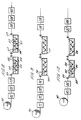
- the specific pattern on a security thread produced by the above described method corresponds to the Cleartext concept as described in EP-B-0319157 and shown in figure 1; which shows a security thread comprising a clear substrate which is covered with a magnetic metal layer 10, with the letters 11 of the word PORTALS being formed from clear metal free regions in the metal layer 10.
- the lines 36 in figure 2 merely illustrate the edges of the security thread and do not indicate the presence of deposited magnetic metal.
- the Cleartext design could also be produced in blocks as shown in figure 3, in which the blocks 14 of metal free characters are separated by gaps 15, which extend completely across the width of the thread and define isolated conductive blocks of magnetic metal each with a specified length which is important for radio frequency or microwave detection.
- the lines 37 where they appear in the metal free zones serve only to illustrate the edges of the security thread and do not indicate the presence of deposited magnetic metal. It is further possible to produce designs which combine mixtures of the concepts of the above two specifications, i.e.
- a thread which has regions of metal characters as described in the US specification and also regions of metal free characters as described in the European specification, as shown in figure 4, in which regions of metal free characters such as 16 are separated by regions of metal characters such as region 17.
- regions of metal free characters such as 16 are separated by regions of metal characters such as region 17.
- isolated conductive blocks of specified lengths are provided in the regions of metal free characters, which is important for radio frequency and microwave detection.
- the lines 38 where they appear in the regions of metal characters (e.g. 17) serve only to illustrate the edges of the security thread and not to indicate the presence of deposited metal.
- the characters will typically be symbols such as alphanumeric characters or characters for written languages such as Japanese, Chinese or Arabic. Alternatively the specific pattern could be in the form of a machine readable code such as a bar code.
- Figures 5a, 5b and 5c show examples of such a bar code on its own (in figure 5a a region 21 of bar code is shown) and combined with non-coded regions forming a text (in figure 5b a region 23 with metal free characters is shown separated from two bar code regions 22 by gaps 31 and in figure 5c a region with metal characters is shown separating two bar code regions 24).
- the lines 39, 40 and 41 serve only to mark the edges of the security threads and do not indicate the presence of deposited magnetic metal at the edges of the metal free regions or the regions with metal characters.
- the pattern intrinsically embodies optically readable information which may be determined by visual inspection and/or by machine.
- each ribbon 18 comprises a section of printed text (e.g. section 33) a tracking line (e.g. 20) and an unprinted gap (e.g. 19) between the section of printed text (e.g. 33) and the tracking line (e.g. 20).
- the dotted lines 34 and 35 indicate the boundaries of the ribbon 18. Whilst for clarity only a small number of lines of text are shown in each text section in the figure 6, in practice a text section typically has twenty to fifty lines of text and a ribbon is typically 30 - 90 mm wide.
- Tracking lines are not required where there is no requirement for lateral registration between text and thread. Tracking lines may also be omitted where registration during slitting may be achieved by other means, for example by optical tracking of the text.
- the ribbons are slit from the film and the threads then slit from the ribbons.
- the magnetic metal present on a security thread slit from the film provides two security features in that it is visually discernible (e.g. it defines alphanumeric characters) and is magnetically detectable (thereby being suitable for use with known magnetic detectors used for security threads).
- Magnetic detection may take place in a number of ways. In the simplest form, only the presence of a magnetic material in the appropriate region of the security article, e.g. banknote, is determined, by assessing the magnetic remanence required with reference to a lower and optionally an upper threshold limit. Alternatively or additionally, measurement of the coercivity or other magnetic property of the magnetic content of the security thread may be made.
- the magnetic metal can be desposited as standard MICR (Magnetic Ink Character Recognition) symbols so that the symbols can be recognised by currently available MICR detectors or alternatively symbols such as alphanumeric characters could be recognised by modified MICR detectors.
- MICR detection apparatus should be construed as covering both standard and modified MICR detection apparatus.
- a bar code could be desposited and read by detectors designed to read a form of bar code.
- Other detection systems operate by writing a signal into the magnetic material and subsequently reading it back in a manner analogous to analogue or digital recording; such detectors must be configured to take into account the pattern in which the magnetic metal is present so that there is no unacceptable interference with the recorded/replayed signal.
- the magnetic metal can also allow the thread to be detected by other detection techniques making use of the metallic/conductive content (e.g. radio frequency or microwave detection, resonance and capacitive coupling).
- detection techniques e.g. radio frequency or microwave detection, resonance and capacitive coupling.
- the security thread is also suitable for use as magnetic strips in security cards.
- the security thread is preferably embedded in laminated cards or face mounted and again provides at least a visually discernible security feature and a magnetically detectable security feature.
- the magnetic metal can be deposited in the form of a bar code and/or a signal recorded using the magnetic metal of the security thread.
- a catalyst layer is applied uniformly at 71 over a PET substrate dispensed from a roll 70 in accordance with known techniques and then dried/activated by drier 72 and oven 73.
- a barrier coating is then applied at 74 in a pattern over the catalyst layer to isolate the underlying catalyst.
- the film is then immersed in a plating bath 75 (the film being passed over rollers 76) and metal is electrolessly deposited in the regions not covered by the barrier coating, i.e. the barrier coating must be printed in the reverse image to that of the chosen pattern of magnetic metal.
- the film bearing catalyst is then rinsed, dried and cut at 77, 78 and 79.
- activation of the catalyst may follow the application of the barrier coating and the process need not be a continuous process.
- a different non-preferred method of producing the required end result is to print at 81 a conductive ink or coating in a specific pattern onto one side of a suitable substrate dispensed from a roll 80.
- a web of the substrate is then dried at 82 and then immersed in an electroplating bath 83 using rollers 84 and continual electrical contact is made with the conducting printed pattern, e.g. by means of a conducting roller 85.
- the conducting ink layer then acts as the cathode for deposition by electroplating from a suitable plating bath 83 for the required magnetic metal/alloy, which is then deposited in the required pattern.
- the electroplated film is then rinsed in bath 86, dried at 87 and cut at 88.
- a further non-preferred method is to apply at 91 a transparent conducting coating, e.g. of indium oxide, tin oxide or combination thereof to a clear flexible substrate dispensed from a roll 90 such that it is uniformly coated all-over, to provide an electrically resisting barrier coating at 92 in a chosen pattern over the conducting layer and to then deposit magnetic metal by electroplating in a bath 93 in the non-printed regions, with a conducting roller 94 applying a current.
- the barrier coating pattern must not interfere with electrical contact with the conducting layer during the plating process.
- the electroplated film is rinsed at 95, dried at 96 and cut at 97.
- a top layer of a different metal may be applied over the magnetic metal where the latter is generated by either the electroplating or the electroless technique.
- a film is dispensed from a roll 100, printed with a catalytic material at 101, dried at 102, the catalytic material is activated in an oven 103 and the film passed through a bath 104 where magnetic metal is electrolessly deposited. Then the magnetic metal plated film is run through an electroplating bath 105 with a suitable cathode connection made by rollers 109 to deposit a top layer of some other metal, such as tin, nickel or copper.
- the bath 105 could be an electroless bath and the film bearing electrolessly deposited magnetic metal could be run through the electroless bath containing non-magnetic metal whilst the film is still wet (it has been found that there is enough catalytic activity present at the surface of the deposited magnetic metal to cause electroless deposition of the non-magnetic metal).
- Such other metal may be required to provide a modified appearance or other property to the upper surface of the magnetic metal.
- the film with two metal layers is then rinsed at 106, dried at 107 and cut at 108.
- An intermediate layer of non-magnetic metal can be deposited between the catalyst and the magnetic metal, e.g. using the electroless technique described in the previous paragraph, (nickel is a preferred intermediate layer).
- the clear plastic substrate may have a dye or luminescing agent incorporated in it to provide colour to the film when viewed in the appropriate illumination.
- a dye or luminescing agent incorporated in it to provide colour to the film when viewed in the appropriate illumination.
- Further layers containing dyes, luminescing agents, optically active layers may be added to the basic film to further enhance the visual properties, as disclosed in our EP-B-0319157.
- the security thread of the present invention could be designed to allow sensing by equipment commonly used to read magnetic ink text on a cheque, i.e. magnetic ink character recognition apparatus.
- the signal provided by the magnetic metal on the thread would be particular to the pattern of the magnetic thread.
- Security threads could be used for purposes other than for security articles, e.g. for tear tapes and other tamper evidencing devices for containers.
- a catalyst ink is prepared by dissolving 0.08 kg of palladium acetate in a mixture of 1.6 l of water and 0.32 l of concentrated ammonium hydroxide; the molar ratio of ammonia to palladium was 13:7.
- the palladium solution is added to a solution of polyvinylalcohol (M.W. 125,000,88 mole percent hydrolysed) in water to produce a catalyst ink comprising 0.24 percent palladium with a viscosity of about 20 cp.
- An aqueous, catalytic ink comprising palladium and a heat-curing vinyl copolymer is prepared by adding palladium acetate and phosphate ester plasticized vinyl chloride-vinyl acetate copolymer (Geon 590K20 (trade mark)) copolymer from B.F.
- Either of the catalyst inks of the examples given above is then used in a rotogravure printing press and transferred in a chosen pattern from a gravure roll onto a moving web of 23 ⁇ m thick polyethylene terephthlate (PET, Hostaphan 4400 (trade mark)) unwound from a roll and travelling at a linear speed of 30 m/min.
- PET polyethylene terephthlate
- the printed film is next passed through an air drying oven (air temperature 40°-80°C, residence time about 3 s) to produce a catalytically inert film which is then re-wound.
- the printed film is next heat-activated by unwinding the catalytically inert film and passing the film at 3 m/min through a further oven with an air temperature of 160 C and residence time 12 s to produce a catalytically-active film which is re-wound.
- the chosen catalyst pattern is chosen to produce eventually a security thread according to figure 1 with metal deposited in the region 10.
- the bath is equipped with PTFE-coated heaters, a pump for continuous filtration of the solution, and an air line for air agitation of the solution prior to plating.
- the bath is operated at 70 C, in order to ensure the solubility of the components and to reduce the concentration of dissolved oxygen.
- Matrix experiments have been conducted in which all the components were varied in a systematic manner and the magnetic properties of the resulting magnetic cobalt layer and the metal deposition rate were measured, showing that the bath could meet the specifications demanded in the production of the magnetic film required for the invention.
- the exact electroless bath composition, especially of sodium hypophosphite, cobalt sulphate, and glycine had a profound effect on the magnetic properties of the deposited magnetic layer.
- the magnetic properties of the deposited cobalt could be changed in a controlled and understandable manner by varying the chemical components in the bath.
- a feature of the electroless deposition of cobalt (present as cobalt metal or cobalt phosphide), is that an induction time is observed before plating commences (typically 10-30 s but it can be longer or shorter and is thought to be due to the need to remove excess dissolved oxygen); this is followed by a steady deposition rate of typically 1 nms -1 metal thickness.
- Increasing the concentration of hypophosphite increases both the magnetic coercivity and metal deposition rate.
- Increasing the cobalt concentration decreases the coercivity by increasing the size of the metal alloy crystallites; conversely, reducing the cobalt concentration increases the coercivity by reducing the size of the crystallites.
- Increasing or decreasing the concentration of glycine reduces the coercivity.
- Nickel sulphate or zinc sulphate can also be added to further modify the deposition rate or the magnetic properties, especially to raise the coercivity to the particular requirement.
- the film is conveyed through a series of rinsing tanks containing deionised water, dried and rewound.
- the cobalt-based magnetic metal is present on the film in a manner similar to figure 6, with transparent metal-free letters forming the text legend "PORTALS" in the text sections (e.g. 33).
- the magnetic characteristics of a portion of the film are determined by a B-H Looper; optionally a Vibrating Sample Magnetometer can be used.
- the portion of the film used in the B-H Looper or Vibrating Sample Magnetometer should be chosen to be of a size sufficient to give an average reading since the presence of the text leads to fluctuations in magnetic properties across the film; a 5 centimetre square area is typically but not exclusively used. Measurements are taken parallel to or transverse to the lines of text, according to the requirements of the magnetic detection system ultimately used to authenticate the security thread.
- the roll of film is next transported to a coating machine.
- the roll is next unwound and conveyed through the machine.
- a barrier coating of a copolymer of vinyl chloride and vinyl acetate is gravure-coated from solution over the magnetic metal to a dry film weight of 2 gm -2 and air-dried.
- the film is next re-wound, returned to the input end of the coating machine and passed through again to apply an adhesive coating of an ethylene/acrylic acid copolymer emulsion on to both sides, giving a dry film weight of 5 gm -2 each side.
- each thread comprised a region of magnetic metal forming 70% of the total area of one side with clear metal-free light-permeable regions comprising 30% of the total area of that side and forming the legend "PORTALS" as shown in figure 1.
- FIG 7 there is shown a cross-section through a part of the resulting security thread having magnetic metal deposited on a substrate.
- the film of polyethyleneterepthlate (PET, Hostaphan 4400) is shown as 29.
- the catalyst ink printed on the film 29 is shown as a layer 28.
- the deposited magnetic metal is shown as a layer 27.
- the barrier coating is shown as a layer 26.
- the two layers of adhesive are shown as two layers 30.
- the individual security threads are incorporated into banknote paper on a cylinder mould machine such that they are wholly enclosed with fibre to form an embedded security thread.
- banknotes incorporating the security thread are released into circulation.
- the banknotes are fed into a high-speed used note sorting machine.
- the magnetic content of the security thread is interrogated by a magnetic remanence detector fitted to the sorting machine.
- Banknotes containing a security thread producing the correct range of remanence signals are directed for re-issue or destruction, according to their condition and fitness for re-issue.
- Banknotes not containing a security thread producing the correct remanence signal are directed to manual inspection as being potential counterfeits.
- the barrier coating is a copolymer of vinylidene chloride and acrylonitrile to a dry film weight of 2 gm -2 .
- One of the catalyst inks given in the examples above is printed in a Cleartext pattern (to produce security threads as shown in figure 1) onto 23 ⁇ m thick PET film using a flexographic printing press at 21 m/min web speed and air dried.
- the dry ink pattern is heated for 1 minute in 190°C air to activate the catalyst.
- a cobalt electroless bath is prepared from cobalt sulphate heptahydrate, sodium citrate, sodium borohydride, ammonium sulphate, sodium hypophosphite and ammonia to provide an aqueous solution of pH 8.3 of the following composition: cobalt 0.11 Molar citrate 0.14 Molar borohydride 0.31 Molar sulphate 0.76 Molar hypophosphite 0.14 Molar
- the printed activated film is passed through and immersed for 2 minutes in the cobalt plating bath at 55°C providing a pin hole-free, magnetic cobalt deposit defining a pattern of sharp, metal-free characters.
- the film is next further processed as described in example 1.
- the magnetic detection on the used note sorting machine interrogates both the magnetic remanence and coercivity of the security thread. If either property is found to be outside the pre-set limits, the banknote is directed to manual inspection.
- a separate radio frequency or microwave detector interrogates the metallic content of the security thread to verify the specific distance of continuous metal between the breaks extending across the full width of the thread.
- a separate metal detector based on capacitive coupling is used to interrogate the metal content of the security thread.
- the magnetic metal is deposited in a series of bars which eventually extend across the security thread in a bar code according to figure 5a.
- a detector is used to verify both the magnetic remanence of the metallic content of the security thread and the magnetic code formed from the specific pattern in which the magnetic metal was deposited.
- MICR-type detector Magnetic Ink Character Recognition
- MICR-type detector Magnetic Ink Character Recognition
- a modified MICR-type detector is used to verify the pattern of the magnetic metal and by magnetic means identify the pattern formed from the clear metal-free regions in the security thread.
- an optical detector is used to determine by optical means the pattern of the magnetic metal, complementing the verification of the presence of the metal by the magnetic detector.
- the optical detection is based on the interruptions in the optical transmission through the banknote in the infra-red region, i.e. the detector is a shadow type detector.
- the reflected light image of the metallic regions of the security thread is also detected and analysed and compared to the transmitted light image.
- the adhesive coatings applied to each side of the thread incorporates a pigment which fluoresced red when placed under a suitable UV excitation lamp.
- a security thread is manufactured in accordance with example 1.
- the thread is then laid across a rectangular block of transparent or translucent plasticized polyvinyl chloride (PVC).
- PVC polyvinyl chloride
- a clear PVC laminating film is laid over the thread and the whole assembly placed in an embossing press heated to 180 C.
- the security thread is incorporated into a laminated plastic card with embossed information suitable for use as, e.g. an identity card.
- it is transported through a reading device incorporating a magnetic remanence detector such that the magnetic metal content of the security thread passes the detector head.
- the security thread is encoded with information in a manner analogous to that used to encode magnetic stripes on credit and charge cards etc.
- the security thread thus combines the functions of such stripes with providing visual security for the general public.
- a photograph or other identifying device is incorporated within the laminated card.
- a continuous web of 12 ⁇ m thick polyester is unwound from a roll and passed through a coating machine.
- a layer of catalyst containing palladium was uniformly gravure coated over one side of the film to a dry coating weight of approximately 1 gm -2 .
- the coated film is then passed through a printing machine and a vinyl lacquer flexo-printed over the catalyst layer and dried; the layer is printed in a chosen pattern such that security thread manufactured from the film has regions corresponding to the clear regions identified in figure 1.
- the web is then passed through a hot air oven at 180°C and the catalyst heat activated.
- the web is then passed through a plating bath containing a cobalt solution as described in example 1.
- a layer of cobalt-based alloy was then electrolessly deposited over the regions of catalyst not covered by the patterned vinyl lacquer which constitutes a barrier to the deposition process.
- the resultant magnetic metal was thus deposited in a pattern according to figure 1.
Landscapes
- Physics & Mathematics (AREA)
- General Physics & Mathematics (AREA)
- Credit Cards Or The Like (AREA)
- Paper (AREA)
Claims (56)
- Verfahren zur Herstellung eines Sicherheitsprodukts geeignet für den Gebrauch in Zusammenhang mit Sicherheitsartikeln wie zum Beispiel Sicherheitspapier, wobei ein magnetisches Metall in einen Film polymeren Substrats abgelagert wird, indem das Substrat durch eine, das magnetische Metall enthaltende Lösung fließt, die Oberfläche des Substrats vor dem Eintauchen in die Lösung vorbehandelt wird, und das Substrat mit dem abgelagerten magnetischen Metall zur Herstellung des Sicherheitsprodukts zerteilt wird, dadurch gekennzeichnet, daß die Vorbehandlung der Substratoberfläche die Ablagerung des magnetischen Metalls auf dem Substrat in einem gewähltem Muster sicherstellt, so daß bei der Herstellung des Sicherheitsprodukts durch Zerteilen des Films das magnetische Metall auf dem Sicherheitsprodukt ein spezifisches Muster aufweist und sowohl ein visuell erkennbares als auch ein magnetisch erfaßbares Sicherheitsmerkmal liefert.
- Verfahren nach Anspruch 1, dadurch gekennzeichnet, daß es sich bei dem Sicherheitsprodukt um einen Sicherheitsfaden handelt, der aus dem Film mit Hilfe eines Schlitzverfahrens hergestellt wird, wobei der Sicherheitsfaden für den Gebrauch in Sicherheitspapier wie zum Beispiel in dem für Banknoten verwendeten Papier geeignet ist.
- Verfahren nach Anspruch 1, dadurch gekennzeichnet, daß es sich bei dem Sicherheitsprodukt um einen Sicherheitsstreifen handelt, der von dem Film abgetrennt wird, wobei sich der Sicherheitsstreifen zum Einbau in oder zum Befestigen an die Oberfläche eines Sicherheitsdokuments oder einer Sicherheitskarte eignet.
- Verfahren nach Anspruch 1, dadurch gekennzeichnet, daß es sich bei dem Sicherheitsprodukt um einen Sicherheitsflecken handelt, der von dem Film abgetrennt wird, wobei sich der Sicherheisflecken zum Befestigen an die Oberfläche eines Sicherheitsdokuments oder einer Sicherheitskarte eignet.
- Verfahren nach einem der vorhergehenden Ansprüche, dadurch gekennzeichnet, daß die Vorbehandlung das Auftragen eines katalytisch aktiven Stoffes auf das Substrat aufweist, wobei das magnetische Metall durch ein elektroloses Verfahren auf Teilabschnitte des genannten Substrats abgelagert wird, die mit dem katalytisch aktiven Stoff versehen sind, während das Substrat in die das magnetische Material enthaltende Lösung eingetaucht wird.
- Verfahren nach Anspruch 5, dadurch gekennzeichnet, daß der katalytisch aktive Stoff auf dem Substrat Palladium aufweist.
- Verfahren nach Anspruch 5 oder 6, dadurch gekennzeichnet, daß es sich bei dem auf dem Substrat abgelagerten magnetischen Metall um Kobalt oder eine Kobalt-enthaltende Legierung handelt.
- Verfahren nach Anspruch 7, dadurch gekennzeichnet, daß das magnetische Metall Kobalt und Phosphor aufweist.
- Verfahren nach Anspruch 7 oder 8, dadurch gekennzeichnet, daß sich ein nicht-magnetisches Metall in einem elektolosen Verfahren direkt auf dem katalytisch aktiven Stoff ablagert und sich das magnetische Metall über dem nicht-magnetischen Metall ablagert, so daß der hergestellte Sicherheitsfaden eine Schicht nicht-magnetischen Metalls zwischen dem katalytisch aktiven Stoff und dem magnetischen Metall aufweist.
- Verfahren nach einem der Ansprüche 5 bis 9, dadurch gekennzeichnet, daß der katalytisch aktive Stoff auf das Substrat durch Stempeln mit einer den katalytisch aktiven Stoff enthaltenden Stempellösung aufgetragen wird.
- Verfahren nach Anspruch 10, dadurch gekennzeichnet, daß die Stempellösung im wesentlichen frei von Zinn ist.
- Verfahren nach einem der Ansprüche 5 bis 11, dadurch gekennzeichnet, daß das polymere Substrat mit Hilfe eine Spendevorrichtung als fortlaufende Schicht verteilt wird, wobei die fortlaufende Schicht durch eine Vorrichtung für die Ablagerung des katalytisch aktiven Stoffes auf der Schicht geleitet wird und anschließend die katalytisch aktiven Stoff enthaltende Schicht durch eine das magnetische Metall enthaltende Lösung hindurchgeleitet wird
- Verfahren nach Anspruch 12, dadurch gekennzeichnet, daß die Vorbehandlung die uniforme Verwendung des katalytisch aktiven Stoffes auf der Oberfläche des Substratfilms aufweist, weiter die Verwendung einer Grenzbeschichtung auf Teilabschnitten des verwendetern katalytisch aktiven Stoffes, der nicht-beschichtete katalytisch aktive Stoff das resultierende gewählte Muster bildet, und für die Aktivierung des katalytisch aktiven Stoffes sorgt, und sich der magnetische Werkstoff in einem elektrolosen Verfahren nur auf den mit einer Grenzbeschichtung versehenen Teilabschnitten ablagert.
- Verfahren nach einem der vorhergehenden Ansprüche, dadurch gekennzeichnet, daß sich das magnetische Metall auf dem Substrat mit einer Dicke im Bereich von 0.01 bis 3.0 µm ablagert.
- Verfahren nach einem der Ansprüche 1 bis 4, dadurch gekennzeichnet, daß die Vorbehandlung das Stempeln des Substrats aufweist, um dieses mit einem leitenden Werkstoff zu versehen, und sich das magnetische Metall beim Eintauchen in die Lösung auf dem leitenden Werkstoff mit Hilfe einer Elektolyse ablagert.
- Verfahren nach einem der Ansprüche 1 bis 4, dadurch gekennzeichnet, daß die Vorbehandlung die Beschichtung des Substrats mit einer transparenten leitenden Schicht und das Auftragen einer elektrischen Sperrschicht in einem Muster auf die transparente leitenden Schicht aufweist, wobei sich das magnetische Metall in den Bereichen der leitenden Schicht ablagert, die nicht mit der elektrischen Sperrschicht bedeckt sind, wenn das Substrat in die Lösung eingetaucht wird und Strom durch die leitende Schicht fließt.
- Verfahren nach Anspruch 16, dadurch gekennzeichnet, daß das Substrat mit einer transparenten leitenden Schicht beschichtet ist, welche Indiumoxyd, Zinnoxyd oder eine Verbindung von beiden aufweist.
- Verfahren nach einem der vorhergehenden Ansprüche, dadurch gekennzeichnet, daß es zusätzlich den Arbeitsschritt des Auftragens einer Schutz- und/oder Haftschicht auf dem magnetischen Metall aufweist.
- Verfahren nach Anspruch 18, dadurch gekennzeichnet, daß die Schutz- und/oder Haftschicht auf das magnetische Metall vor dem Zerteilen des Films zur Herstellung des Sicherheitsprodukts aufgetragen wird.
- Verfahren nach einem der vorhergehenden Ansprüche, dadurch gekennzeichnet, daß das magnetische Metall auf einem trans-parenten polymeren Substrat abgelagert wird, so daß das Sicherheitsprodukt mit einem visuell erkennbares Sicherheitsmerkmal versehen wird, welches im durchgelassenen Licht erkennbar ist.
- Verfahren nach einem der vorhergehenden Ansprüche, dadurch gekennzeichnet, daß sich das magnetische Metall auf dem Substrat in der Weise ablagert, so daß das aus dem Film hergestellte Sicherheitsprodukt ein spezifisches Muster aufweist, welches mit Hilfe eines Detektors magnetisch identifiziert werden kann.
- Verfahren nach einem der vorhergehenden Ansprüche, dadurch gekennzeichnet, daß sich das magnetische Metall auf dem Substrat in der Weise ablagert, so daß das aus dem Film hergestellte Sicherheitsprodukt ein Sicherheitsmerkmal aufweist, das mit Hilfe eines Metalldetektors nachweisbar ist.
- Verfahren nach einem der vorhergehenden Ansprüche, dadurch gekennzeichnet, daß das magnetische Metall in einem fortlaufenden Prozeß abgelagert wird.
- Sicherheitsprodukt, geeignet für das Einbauen in oder das Anbringen an die Oberfläche von Sicherheitspapier, dadurch gekennzeichnet, daß es folgendes aufweist:ein polymeres Substrat,einen katalytisch aktiven Stoff, der zumindest einen Teil der polymeren Substratoberfläche bedeckt, undeine Schicht eines in einem elektrolosen Verfahren abgelagerten magnetischen Metalls, das zumindest einen Teil des katalytisch aktiven Stoffes mit einer Dicke im Bereich von 0.01 bis 3,0 µm bedeckt, dadurch gekennzeichnet, daßdie magnetische Metallschicht ein spezifisches Muster aufweist und ein Sicherheitsprodukt mit einem sowohl visuell erkennbaren als auch mit einem magnetisch nachweisbaren Sicherheitsmerkmal liefert, wobei das Sicherheitsprodukt einen durchschnittlich zurückbleibenden Magnetismus im Bereich von 0.001 bis 0.05 emu cm-2 aufweist.
- Sicherheitsprodukt nach Anspruch 24, dadurch gekennzeichnet, daß es als Sicherheitsfaden in Sicherheisgegenstände, einschließlich Sicherheitspapier, wie es für Banknoten verwendet wird, eingefügt werden kann.
- Sicherheitsprodukt nach Anspruch 24, dadurch gekennzeichnet, daß es als Sicherheitsstreifen verwendet werden kann, der an der Oberfläche eines Sicherheitsdokuments oder einer Sicherheitskarte befestigt werden kann.
- Sicherheitsprodukt nach Anspruch 24, dadurch gekennzeichnet, daß es als Sicherheitsflecken verwendet werden kann, der an der Oberfläche eines Sicherheitsdokuments oder einer Sicherheitskarte befestigt werden kann.
- Sicherheitsprodukt nach einem der Ansprüche 24 bis 27, dadurch gekennzeichnet, daß das in einem elektrolosen Verfahren abgelagerte magnetische Metall Kobalt und wahlweise einen oder mehrere der Stoffe Nickel, Phosphor oder Eisen oder Legierungen davon aufweist.
- Sicherheitsprodukt nach einem der Ansprüche 24 bis 28, dadurch gekennzeichnet, daß es eine magnetische Koerzitivkraft im Bereich von 100 bis 2,000 Oe aufweist.
- Sicherheitsprodukt nach Anspruch 29, dadurch gekennzeichnet, daß es eine magnetische Koerzitivkraft im Bereich von 100 bis 1,000 Oe aufweist.
- Sicherheitsprodukt nach einem der Ansprüche 24 bis 30, dadurch gekennzeichnet, daß es einen zurückbleibenden Magnetismus im Bereich von 0.005 bis 0.025 emu cm-2 aufweist.
- Sicherheitsprodukt nach einem der Ansprüche 24 bis 31, dadurch gekennzeichnet, daß der katalytisch aktive Stoff Palladium aufweist.
- Sicherheitsprodukt nach einem der Ansprüche 24 bis 32, dadurch gekennzeichnet, daß der katalytisch aktive Stoff im wesentlichen frei von Zinn ist.
- Sicherheitsprodukt nach einem der Ansprüche 24 bis 33, dadurch gekennzeichnet, daß die magnetische Metallschicht eine Dicke im Bereich von 0.2 bis 0.5 µm aufweist.
- Sicherheitsprodukt nach einem der Ansprüche 24 bis 34, dadurch gekennzeichnet, daß es zusätzlich eine Metallschicht aufweist, die zumindest teilweise das magnetische Metall bedeckt.
- Sicherheitsprodukt nach einem der Ansprüche 24 bis 35, dadurch gekennzeichnet, daß der katalytisch aktive Stoff in dem spezifischen Muster auf das Substrat gestempelt wird.
- Sicherheitsprodukt nach einem der Ansprüche 24 bis 36, dadurch gekennzeichnet, daß zumindest einige Teile des Substrats, die nicht mit dem magnetischen Werkstoff bedeckt sind, das spezifische Muster, welches ein visuell erkennbares Sicherheitsmerkmal darstellt, definieren.
- Sicherheitsprodukt nach einem der Ansprüche 24 bis 37, dadurch gekennzeichnet, daß das spezifische Muster alphanumerische Zeichen aufweist.
- Sicherheitsprodukt nach einem der Ansprüche 24 bis 38, dadurch gekennzeichnet, daß es eine zweifarbige Schicht aufweist.
- Sicherheitsprodukt nach einem der Ansprüche 24 bis 39, dadurch gekennzeichnet, daß es eine holografische Schicht aufweist.
- Sicherheitsprodukt nach einem der Ansprüche 24 bis 40, dadurch gekennzeichnet, daß es eine ablenkende Schicht aufweist.
- Sicherheitsprodukt nach einem der Ansprüche 24 bis 41, dadurch gekennzeichnet, daß das Substrat darin Farb- oder Leuchtstoff aufweist.
- Sicherheitsprodukt nach einem der Ansprüche 24 bis 42, dadurch gekennzeichnet, daß das polymere Substrat transparent oder durchscheinend ist, wodurch das visuell erkennbare Sicherheitsmerkmal ein Sicherheitsmerkmal darstellt, das in Durchlicht erkennbar ist.
- Sicherheitsprodukt nach einem der Ansprüche 24 bis 43, dadurch gekennzeichnet, daß es zusätzlich eine Schutz- und/oder Haftschicht auf dem magnetischen Metall aufweist.
- Sicherheitsprodukt nach einem der Ansprüche 24 bis 44, dadurch gekennzeichnet, daß das spezifische Muster wesentliche Information in sich vereinigt.
- Sicherheitsprodukt nach Anspruch 45, dadurch gekennzeichnet, daß das spezifische Muster einen Strichcode darstellt, der maschinenlesbar ist.
- Sicherheitsprodukt nach einem der Ansprüche 24 bis 45, dadurch gekennzeichnet, daß es sich bei dem Sicherheitsprodukt um einen Sicherheitsfaden handelt, der in das Sicherheitspapier in eingelagerter Form oder Fensterform eingefügt ist.
- Banknote, die Sicherheitspapier nach Anspruch 47 aufweist.
- Film, der in Sicherheitsprodukte wie zum Beispiel Sicherheitsfäden für Sicherheitspapiere einschließlich Banknoten zerteilt werden kann, dadurch gekennzeichnet, daß der Film folgendes aufweist:ein polymeres Substrat,einen katalytisch aktiven Stoff, der zumindest einen Teil einer polymeren Substratoberfläche bedeckt, undeine in einem elektrolosen Verfahren abgelagerte magnetische Metallschicht, die zumindest einen Teil des katalytisch aktiven Stoffes in einer magnetischen Metallschicht mit einer Dicke im Bereich von 0.01 bis 3.0 µm bedeckt, wobeidie magnetische Metallschicht ein gewähltes Muster aufweist, so daß nach Zerteilen des Films in Sicherheitsprodukte die magnetische Metallschicht sowohl ein visuell erkennbares Sicherheitsmerkmal als auch ein magnetisch nachweisbares Sicherheitsmerkmal liefert und das Sicherheitsprodukt einen zurückbleibenden Magnetismus im Bereich von 0.001 bis 0.05 emu cm-2 aufweisen kann.
- Film nach Anspruch 49, dadurch gekennzeichnet, daß er zusätzlich eine Schutz- und/oder Haftschicht auf dem magnetischen Metall aufweist.
- Film nach den Ansprüchen 49 und 50, dadurch gekennzeichnet, daß das im elektrolosen Verfahren abgelagerte magnetische Metall Kobalt oder wahlweise einen oder mehrere der Stoffe Nickel oder Phosphor oder Legierungen davon, aufweist.
- Film nach den Ansprüchen 49, 50 oder 51, dadurch gekennzeichnet, daß die magnetische Metallschicht einen Sicherheitsfaden aufweist, der vom Film mit einer magnetischen Koerzivkraft im Bereich von 100 bis 2,000 Oe abgetrennt wird.
- Film nach einem der Ansprüche 49 bis 52, dadurch gekennzeichnet, daß die magnetische Metallschicht einen Sicherheitsfaden aufweist, der vom Film mit einem zurückbleibenden Magnetismus im Bereich von 0.005 bis 0.025 emu cm-2 abgetrennt wird.
- Film nach einem der Ansprüche 49 bis 53, dadurch gekennzeichnet, daß der katalytisch aktive Stoff Palladium aufweist.
- Film nach Anspruch 54, dadurch gekennzeichnet, daß der katalytisch aktive Stoff im wesentlichen frei von Zinn ist.
- Film nach einem der Ansprüche 49 bis 53, dadurch gekennzeichnet, daß das gewählte Muster wesentliche Information in sich vereinigt.
Applications Claiming Priority (6)
| Application Number | Priority Date | Filing Date | Title |
|---|---|---|---|
| GB9415780A GB9415780D0 (en) | 1994-08-04 | 1994-08-04 | A security thread, a film and a method of manufacture of a security thread |
| GB9415780 | 1994-08-04 | ||
| GB9415931A GB9415931D0 (en) | 1994-08-09 | 1994-08-09 | A security thread, a film and a method of manufacture of a security thread |
| GB9415931 | 1994-08-09 | ||
| US08/289,440 US5631039A (en) | 1994-08-04 | 1994-08-12 | Security thread, a film and a method of manufacture of a security thread |
| PCT/GB1995/001800 WO1996004143A1 (en) | 1994-08-04 | 1995-07-28 | A security product, a film and a method of manufacture of a security product |
Publications (2)
| Publication Number | Publication Date |
|---|---|
| EP0773872A1 EP0773872A1 (de) | 1997-05-21 |
| EP0773872B1 true EP0773872B1 (de) | 1998-10-21 |
Family
ID=27267317
Family Applications (1)
| Application Number | Title | Priority Date | Filing Date |
|---|---|---|---|
| EP95927043A Expired - Lifetime EP0773872B1 (de) | 1994-08-04 | 1995-07-28 | Sicherheitsprodukt, film und verfahren zur herstellung eines sicherheitsprodukts |
Country Status (8)
| Country | Link |
|---|---|
| EP (1) | EP0773872B1 (de) |
| AU (1) | AU3120595A (de) |
| DE (1) | DE69505539T2 (de) |
| DK (1) | DK0773872T3 (de) |
| ES (1) | ES2125636T3 (de) |
| MA (1) | MA23640A1 (de) |
| TR (1) | TR199500944A1 (de) |
| WO (1) | WO1996004143A1 (de) |
Cited By (3)
| Publication number | Priority date | Publication date | Assignee | Title |
|---|---|---|---|---|
| WO2009053673A1 (en) * | 2007-10-23 | 2009-04-30 | De La Rue International Limited | Improvements in security elements |
| WO2018148688A1 (en) | 2017-02-10 | 2018-08-16 | Crane & Co., Inc. | Authentication and anti-harvesting security feature with machine detectable indicia |
| EP4692457A1 (de) * | 2024-08-08 | 2026-02-11 | Leandro Antonio Goncalves Giordano | Intelligente klinge und herstellungsverfahren dafür |
Families Citing this family (16)
| Publication number | Priority date | Publication date | Assignee | Title |
|---|---|---|---|---|
| DE19650759A1 (de) * | 1996-12-06 | 1998-06-10 | Giesecke & Devrient Gmbh | Sicherheitselement |
| DE19731968A1 (de) * | 1997-07-24 | 1999-01-28 | Giesecke & Devrient Gmbh | Sicherheitsdokument |
| DE19907697A1 (de) | 1999-02-23 | 2000-08-24 | Giesecke & Devrient Gmbh | Wertdokument |
| GB0111452D0 (en) * | 2001-05-10 | 2001-07-04 | Rue De Int Ltd | Method of manufacturing a security item |
| GB0209564D0 (en) | 2002-04-25 | 2002-06-05 | Rue De Int Ltd | Improvements in substrates |
| GB2413179A (en) * | 2004-04-13 | 2005-10-19 | Ezio Panzeri | Security thread reader for detection of both magnetic material and optical markings |
| DE102009042022A1 (de) | 2009-09-21 | 2011-03-24 | Giesecke & Devrient Gmbh | Langgestrecktes Sicherheitselement mit maschinenlesbaren magnetischen Bereichen |
| AR080431A1 (es) | 2010-03-03 | 2012-04-11 | Sicpa Holding Sa | Hilo o tira de seguridad que comprende particulas magneticas orientadas en tinta y procedimiento y medio para producir el mismo |
| EP2882597B1 (de) | 2012-08-01 | 2017-02-01 | Sicpa Holding SA | Optisch variable sicherheitsfäden und -streifen |
| BR112015003927A2 (pt) | 2012-08-29 | 2017-07-04 | China Banknote Printing & Minting Corp | filete ou listra de segurança, processo para fazer o filete ou listra de segurança, uso do filete ou listra de segurança, documento de segurança e processo para fazer o substrato de segurança. |
| JP2016522528A (ja) | 2013-05-02 | 2016-07-28 | シクパ ホルディング ソシエテ アノニムSicpa Holding Sa | セキュリティスレッド又はストライプの製造方法 |
| WO2015085505A1 (en) | 2013-12-11 | 2015-06-18 | Sicpa Holding Sa | Optically variable security threads and stripes |
| RU2668545C2 (ru) | 2014-02-13 | 2018-10-01 | Сикпа Холдинг Са | Защитные нити и полоски |
| PL2965920T3 (pl) | 2014-07-09 | 2018-03-30 | Sicpa Holding Sa | Optycznie zmienne magnetyczne nitki zabezpieczające i paski |
| DE102016001834A1 (de) | 2016-02-17 | 2017-08-17 | Giesecke+Devrient Mobile Security Gmbh | Tragbarer Datenträger mit Hochprägung |
| CN113272087B (zh) | 2019-01-29 | 2024-04-19 | 巴斯夫欧洲公司 | 安全元件 |
Family Cites Families (2)
| Publication number | Priority date | Publication date | Assignee | Title |
|---|---|---|---|---|
| IT1222851B (it) * | 1987-10-08 | 1990-09-12 | Mantegazza A Arti Grafici | Codice di identificazione rilevabile magneticamente per contrassegnare prodotti,documenti e simili |
| GB2227451B (en) * | 1989-01-20 | 1992-10-14 | Bank Of England The Governor A | Coding security threads for bank notes and security papers |
-
1995
- 1995-07-28 DK DK95927043T patent/DK0773872T3/da active
- 1995-07-28 EP EP95927043A patent/EP0773872B1/de not_active Expired - Lifetime
- 1995-07-28 DE DE69505539T patent/DE69505539T2/de not_active Expired - Fee Related
- 1995-07-28 AU AU31205/95A patent/AU3120595A/en not_active Abandoned
- 1995-07-28 ES ES95927043T patent/ES2125636T3/es not_active Expired - Lifetime
- 1995-07-28 WO PCT/GB1995/001800 patent/WO1996004143A1/en not_active Ceased
- 1995-08-02 TR TR95/00944A patent/TR199500944A1/xx unknown
- 1995-08-03 MA MA23981A patent/MA23640A1/fr unknown
Cited By (5)
| Publication number | Priority date | Publication date | Assignee | Title |
|---|---|---|---|---|
| WO2009053673A1 (en) * | 2007-10-23 | 2009-04-30 | De La Rue International Limited | Improvements in security elements |
| US10087583B2 (en) | 2007-10-23 | 2018-10-02 | De La Rue International Limited | Security elements |
| WO2018148688A1 (en) | 2017-02-10 | 2018-08-16 | Crane & Co., Inc. | Authentication and anti-harvesting security feature with machine detectable indicia |
| CN110612215A (zh) * | 2017-02-10 | 2019-12-24 | 克瑞尼股份有限公司 | 具有机器可检测标记的认证和防采收安全特征 |
| EP4692457A1 (de) * | 2024-08-08 | 2026-02-11 | Leandro Antonio Goncalves Giordano | Intelligente klinge und herstellungsverfahren dafür |
Also Published As
| Publication number | Publication date |
|---|---|
| MA23640A1 (fr) | 1996-04-01 |
| DE69505539D1 (de) | 1998-11-26 |
| WO1996004143A1 (en) | 1996-02-15 |
| DE69505539T2 (de) | 1999-06-17 |
| EP0773872A1 (de) | 1997-05-21 |
| ES2125636T3 (es) | 1999-03-01 |
| AU3120595A (en) | 1996-03-04 |
| TR199500944A1 (tr) | 1996-10-21 |
| DK0773872T3 (da) | 1999-06-28 |
Similar Documents
| Publication | Publication Date | Title |
|---|---|---|
| US5631039A (en) | Security thread, a film and a method of manufacture of a security thread | |
| EP0773872B1 (de) | Sicherheitsprodukt, film und verfahren zur herstellung eines sicherheitsprodukts | |
| EP0824405B1 (de) | Magnetisches sicherheitselement enthaltende artikel | |
| EP1497141B1 (de) | Durchsichtiges sicherheitsdokument mit magnetteilchen | |
| EP0563109B1 (de) | Sicherheitsartikel | |
| DE69829889T2 (de) | Sicherheitsvorrichtung mit mehreren Sicherheitsmerkmalen | |
| EP0938417B1 (de) | Verbesserungen in bezug auf sicherheitsdokumente | |
| PL164147B1 (pl) | Element zabezpieczajacy z kontrolowanym wizualnie lub maszynowo oznakowaniem, zwlaszcza dla dokumentów wartosciowychoraz sposób sprawdzania dokumentów wartosciowych PL PL PL | |
| GB2250473A (en) | Security articles | |
| CN101640004A (zh) | 一种全息脱铝复合薄膜材料及防伪物 | |
| EP1064424A1 (de) | Verbessertes verfahren zur herstellung eines sicherheitsfadens | |
| EP1583871B1 (de) | Sicherheitsfolie und verfahren zur herstellung derselben | |
| GB2319215A (en) | Security thread with magnetic patches and visually-readable characters in parallel | |
| US20100154668A1 (en) | Sheet materials with precise gage pin-accurate elements on front and reverse side | |
| KR100407249B1 (ko) | 위조방지용 자성은선 및 이를 포함하는 제품 | |
| KR100561289B1 (ko) | 위조방지용 자성 물질이 부가된 단층 은선 및 이를포함하는 보안용지 |
Legal Events
| Date | Code | Title | Description |
|---|---|---|---|
| PUAI | Public reference made under article 153(3) epc to a published international application that has entered the european phase |
Free format text: ORIGINAL CODE: 0009012 |
|
| 17P | Request for examination filed |
Effective date: 19970110 |
|
| AK | Designated contracting states |
Kind code of ref document: A1 Designated state(s): CH DE DK ES FR GB IT LI NL SE |
|
| 17Q | First examination report despatched |
Effective date: 19970809 |
|
| GRAG | Despatch of communication of intention to grant |
Free format text: ORIGINAL CODE: EPIDOS AGRA |
|
| GRAG | Despatch of communication of intention to grant |
Free format text: ORIGINAL CODE: EPIDOS AGRA |
|
| GRAG | Despatch of communication of intention to grant |
Free format text: ORIGINAL CODE: EPIDOS AGRA |
|
| GRAH | Despatch of communication of intention to grant a patent |
Free format text: ORIGINAL CODE: EPIDOS IGRA |
|
| GRAH | Despatch of communication of intention to grant a patent |
Free format text: ORIGINAL CODE: EPIDOS IGRA |
|
| GRAA | (expected) grant |
Free format text: ORIGINAL CODE: 0009210 |
|
| RAP1 | Party data changed (applicant data changed or rights of an application transferred) |
Owner name: PORTALS LIMITED |
|
| AK | Designated contracting states |
Kind code of ref document: B1 Designated state(s): CH DE DK ES FR GB IT LI NL SE |
|
| PG25 | Lapsed in a contracting state [announced via postgrant information from national office to epo] |
Ref country code: SE Free format text: THE PATENT HAS BEEN ANNULLED BY A DECISION OF A NATIONAL AUTHORITY Effective date: 19981021 Ref country code: NL Free format text: LAPSE BECAUSE OF FAILURE TO SUBMIT A TRANSLATION OF THE DESCRIPTION OR TO PAY THE FEE WITHIN THE PRESCRIBED TIME-LIMIT Effective date: 19981021 Ref country code: LI Free format text: LAPSE BECAUSE OF FAILURE TO SUBMIT A TRANSLATION OF THE DESCRIPTION OR TO PAY THE FEE WITHIN THE PRESCRIBED TIME-LIMIT Effective date: 19981021 Ref country code: CH Free format text: LAPSE BECAUSE OF FAILURE TO SUBMIT A TRANSLATION OF THE DESCRIPTION OR TO PAY THE FEE WITHIN THE PRESCRIBED TIME-LIMIT Effective date: 19981021 |
|
| REG | Reference to a national code |
Ref country code: CH Ref legal event code: EP |
|
| REF | Corresponds to: |
Ref document number: 69505539 Country of ref document: DE Date of ref document: 19981126 |
|
| ET | Fr: translation filed | ||
| REG | Reference to a national code |
Ref country code: ES Ref legal event code: FG2A Ref document number: 2125636 Country of ref document: ES Kind code of ref document: T3 |
|
| NLV1 | Nl: lapsed or annulled due to failure to fulfill the requirements of art. 29p and 29m of the patents act | ||
| REG | Reference to a national code |
Ref country code: CH Ref legal event code: PL |
|
| REG | Reference to a national code |
Ref country code: DK Ref legal event code: T3 |
|
| PG25 | Lapsed in a contracting state [announced via postgrant information from national office to epo] |
Ref country code: DK Free format text: LAPSE BECAUSE OF NON-PAYMENT OF DUE FEES Effective date: 19990802 |
|
| PLBE | No opposition filed within time limit |
Free format text: ORIGINAL CODE: 0009261 |
|
| STAA | Information on the status of an ep patent application or granted ep patent |
Free format text: STATUS: NO OPPOSITION FILED WITHIN TIME LIMIT |
|
| 26N | No opposition filed | ||
| REG | Reference to a national code |
Ref country code: DK Ref legal event code: EBP |
|
| EUG | Se: european patent has lapsed |
Ref document number: 95927043.0 |
|
| REG | Reference to a national code |
Ref country code: GB Ref legal event code: IF02 |
|
| PGFP | Annual fee paid to national office [announced via postgrant information from national office to epo] |
Ref country code: FR Payment date: 20030711 Year of fee payment: 9 |
|
| PGFP | Annual fee paid to national office [announced via postgrant information from national office to epo] |
Ref country code: GB Payment date: 20030723 Year of fee payment: 9 |
|
| PGFP | Annual fee paid to national office [announced via postgrant information from national office to epo] |
Ref country code: DE Payment date: 20030807 Year of fee payment: 9 |
|
| PGFP | Annual fee paid to national office [announced via postgrant information from national office to epo] |
Ref country code: ES Payment date: 20030813 Year of fee payment: 9 |
|
| PG25 | Lapsed in a contracting state [announced via postgrant information from national office to epo] |
Ref country code: GB Free format text: LAPSE BECAUSE OF NON-PAYMENT OF DUE FEES Effective date: 20040728 |
|
| PG25 | Lapsed in a contracting state [announced via postgrant information from national office to epo] |
Ref country code: ES Free format text: LAPSE BECAUSE OF NON-PAYMENT OF DUE FEES Effective date: 20040729 |
|
| PG25 | Lapsed in a contracting state [announced via postgrant information from national office to epo] |
Ref country code: DE Free format text: LAPSE BECAUSE OF NON-PAYMENT OF DUE FEES Effective date: 20050201 |
|
| GBPC | Gb: european patent ceased through non-payment of renewal fee |
Effective date: 20040728 |
|
| PG25 | Lapsed in a contracting state [announced via postgrant information from national office to epo] |
Ref country code: FR Free format text: LAPSE BECAUSE OF NON-PAYMENT OF DUE FEES Effective date: 20050331 |
|
| REG | Reference to a national code |
Ref country code: FR Ref legal event code: ST |
|
| PG25 | Lapsed in a contracting state [announced via postgrant information from national office to epo] |
Ref country code: IT Free format text: LAPSE BECAUSE OF NON-PAYMENT OF DUE FEES Effective date: 20050728 |
|
| REG | Reference to a national code |
Ref country code: ES Ref legal event code: FD2A Effective date: 20040729 |