EP0774562A1 - Stepladder including a bracing shelf - Google Patents
Stepladder including a bracing shelf Download PDFInfo
- Publication number
- EP0774562A1 EP0774562A1 EP96402438A EP96402438A EP0774562A1 EP 0774562 A1 EP0774562 A1 EP 0774562A1 EP 96402438 A EP96402438 A EP 96402438A EP 96402438 A EP96402438 A EP 96402438A EP 0774562 A1 EP0774562 A1 EP 0774562A1
- Authority
- EP
- European Patent Office
- Prior art keywords
- bracing
- stepladder
- shelf
- support section
- steps
- Prior art date
- Legal status (The legal status is an assumption and is not a legal conclusion. Google has not performed a legal analysis and makes no representation as to the accuracy of the status listed.)
- Withdrawn
Links
- 230000007246 mechanism Effects 0.000 claims abstract description 27
- 125000006850 spacer group Chemical group 0.000 description 3
- XAGFODPZIPBFFR-UHFFFAOYSA-N aluminium Chemical compound [Al] XAGFODPZIPBFFR-UHFFFAOYSA-N 0.000 description 1
- 229910052782 aluminium Inorganic materials 0.000 description 1
- 239000004411 aluminium Substances 0.000 description 1
- 230000006866 deterioration Effects 0.000 description 1
- 239000011152 fibreglass Substances 0.000 description 1
- 239000000463 material Substances 0.000 description 1
- 239000004033 plastic Substances 0.000 description 1
- 239000007787 solid Substances 0.000 description 1
- 229920003002 synthetic resin Polymers 0.000 description 1
- 239000000057 synthetic resin Substances 0.000 description 1
- 239000002023 wood Substances 0.000 description 1
Images


Classifications
-
- E—FIXED CONSTRUCTIONS
- E06—DOORS, WINDOWS, SHUTTERS, OR ROLLER BLINDS IN GENERAL; LADDERS
- E06C—LADDERS
- E06C1/00—Ladders in general
- E06C1/02—Ladders in general with rigid longitudinal member or members
- E06C1/38—Special constructions of ladders, e.g. ladders with more or less than two longitudinal members, ladders with movable rungs or other treads, longitudinally-foldable ladders
- E06C1/39—Ladders having platforms; Ladders changeable into platforms
- E06C1/393—Ladders having platforms foldable with the ladder
Definitions
- the present invention relates to stepladders. More specifically, the present invention relates to a stepladder including a bracing shelf acting as a safety device to prevent accidental closing of the stepladder.
- stepladders consist of two sections, a load bearing section including a plurality of steps and a support section, both sections being hinged together at their upper end.
- the stepladder may take a closed position in which the two sections are generally parallel to each other, or an open position in which the two sections define an angle between them.
- stepladders also include a bracing mechanism to maintain a predetermined angle between the load bearing section and the support section when the stepladder is in the open position. Indeed, a mechanism must be provided to stop the opening of the support section with respect to the load bearing section once the predetermined angle between these two sections is reached.
- This bracing mechanism is usually formed of first and second elongate metallic plates pivotally joined to each other at one of their ends.
- the other end of the first elongated plate is pivotally mounted to one side of the load bearing section while the other end of the second elongated plate is pivotally mounted to one side of the support section.
- the angle defined by the stepladder when it is in an open position is therefore defined by the length of the elongated plates since the opening of the stepladder is stopped when the two elongated plates are colinear.
- each stepladder usually includes two bracing mechanisms, one mounted on each side of the stepladder.
- a frequent drawback associated with the use of the aforementioned conventional bracing mechanism is an early deterioration of the bracing mechanism, which renders the stepladder impossible or unsafe to use.
- Another drawback associated with the use of the conventional bracing mechanism is the annoyance factor associated with the use of such mechanism. Indeed, when one wishes to close a conventional stepladder, the two bracing mechanisms must be manually disengaged, which may be awkward since they are mounted on opposite sides of the stepladder. Furthermore, the upward motion required to disengage the conventional bracing mechanism may cause hands or fingers of some users to be pinched between the two pivoting elongated plates when disengaging the bracing mechanism.
- a shelf which is usually pivotally mounted to the support section of the stepladder.
- This pivoting shelf is very convenient since it provides a place to put tools when using the stepladder.
- this shelf creates a safety hazard since a user may accidentally or intentionally use it as a step. In such cases, two treacherous things may happen: first, the pivoting shelf may break and cause the user to fall; secondly, the pivoting shelf may pivot on itself while the user tries to put its foot on it, once again causing him to fall.
- An object of the present invention is therefore to provide an improved stepladder which overcomes the above drawbacks.
- Another object of the invention is to provide a stepladder having a bracing shelf used for preventing the stepladder from closing when the bracing shelf is in a bracing position.
- Yet another aspect of the invention is to provide a stepladder having a bracing shelf including a locking mechanism to prevent accidental closure of the bracing shelf.
- a stepladder comprising:
- stepladder 10 according to a first embodiment of the present invention will be described.
- the stepladder 10 consists of a load bearing section 12, a support section 14, a bracing shelf 16 and a chain 18.
- the load bearing section 12 comprises first and second spaced apart legs 20, 22 and a plurality of intermediary steps 24, 26 and 28 mounted between the legs 20 and 22.
- a top step 30 is also mounted at respective upper ends 32, 34 of the first and second legs 20, 22.
- the load bearing section 12 also includes a transversal member 36 fixedly mounted to the top step 30 and to the first and second legs 20, 22. The purpose of the transversal member 36 will be explained hereinafter.
- the stepladder 10 is illustrated in Figures 1-4 as having three steps 24, 26 and 28. However, a different number of steps could also be provided.
- the step 28 includes an inner edge 29 and an undersurface 31.
- a pair of spacing blocks 33, 35 is fixedly mounted to the undersurface 31 of the step 28, and a pair of locking members 37, 39 is pivotally mounted to the spacing blocks 33, 35, respectively.
- the purpose of the spacing blocks 33, 35 and of the locking members 37, 39 will be explained hereinafter.
- the support section 14 includes first and second spaced apart legs 38, 40, and first and second transversal members 42, 44, mounted between legs 38, 40.
- the support section 14 is hindgedly mounted to the load bearing section 12.
- a pair of hinges 46, 48 are mounted between the second transversal member 44 of the support section 14 and the transversal member 36 of the load bearing section 12.
- the support section 14 may therefore be alternatively positioned in an open position in which they define an angle (illustrated in Figure 1) or in a closed position (not shown), in which the load bearing section 12 and the support section 14 are in a substantially parallel relationship.
- the chain 18 is provided to limit the opening of the support section 14 when the stepladder 10 is in an open position. Indeed, the length of the chain 18 is such that a predetermined angle is defined by the load bearing section 12 and the support section 14 when the chain 18 is under tension.
- the chain 18 is mounted between the lower step 24 of the load bearing section 12 and the first transversal member 42 of the support section 14.
- the bracing shelf 16 includes first and second spaced apart arms 50, 52, a shelf panel 54 and first and second transversal spacers 56, 58.
- Each arm 50, 52 includes a contacting surface 59 and an abutting member 60 (only one being shown) having an inner edge 62.
- the first and second spacers 56, 58 are fixedly mounted between the first and second arms 50, 52, thereby determining the distance separating the first and second arms 50, 52.
- the shelf panel 54 is fixedly mounted over the first and second arms 50, 52.
- the bracing shelf 16 is pivotally mounted to the support section 14 through a pair of D-shaped brackets 64 (only one being shown). Each D-shaped bracket 64 is fixedly mounted to one of the legs 38, 40 of the support section 14. As illustrated, each arm 50, 52 of the bracing shelf 16 is pivotally mounted to one of the first and second legs 38, 40 of the support section 14.
- the bracing shelf 16 may therefore be pivoted between a retracted position illustrated in full lines in Figure 1 or a bracing position illustrated in dashed lines in Figure 1 and in full lines in Figure 3.
- the bracing shelf 16 When the bracing shelf 16 is in the bracing position, the contacting surface 59 of the arms 50, 52 are in contact with the undersurface 31 of the step 28.
- bracing shelf 16 when the bracing shelf 16 is in the position illustrated in dashed lines in Figure 1, it is possible to pivotally engage the locking blocks 37, 39 so that a portion of each locking block 37, 39 lies over a portion of the arms 50, 52 of the bracing shelf 16. This position of the locking blocks 37, 39 is illustrated in Figures 3 and, in more details, in Figure 4.
- the shelf panel 54 of the bracing shelf 16 may be used as a step without the drawbacks discussed above.
- the stepladder 10 could be made of wood, aluminium, plastic, synthetic resin, reinforced fibreglass, etc.
- Stepladder 100 is very similar to stepladder 10 illustrated in Figures 1 to 4. Accordingly, only the differences between stepladders 100 and 10 will be described hereinafter.
- the chain 18 has been eliminated from stepladder 100.
- an abutting member 102 is fixedly mounted at a specific location to the undersurface 31 of the step 28.
- the abutting member 102 is mounted so as to be in contact with the spacing member 58 when the bracing shelf 16 is in the position of Figure 6.
- the abutting member 102 therefore prevents further opening of the support section 14 with respect to the load bearing section 12. It is to be noted that this position of the abutting member 102 does not impede the pivotal movements of the bracing shelf 16 about the support section 14 as previously discussed.
- a manual latching mechanism 104 is mounted to the undersurface 31 of the step 28.
- the latch mechanism 104 is adapted to latch to a block 106 mounted to the transversal spacer 58.
- the function of the latch mechanism 104 is similar to that of the locking members 37, 39 discussed hereinabove.
- One advantage of the latch mechanism 104 over the locking members 37, 39 is that it is automatically engaged when the bracing shelf 16 reaches the position illustrated in Figure 6. Furthermore, the latch mechanism may be easily manually disengaged. It is to be noted that various latch mechanisms are commercially available and could be used as previously described.
- a small chain 108 is mounted between the top step 30 and the second transversal member 44 of the support assembly 14.
- the chain 108 is provided only to help the user to position the support section in an appropriate angle before one attempts to pivot and latch the bracing shelf 16 in the bracing position illustrated in Figure 6.
- the chain 108 is not used to limit the angle between the support section 14 and the load bearing section 12 while the stepladder 100 is used.
- Stepladder 200 is similar to stepladders 10 and 100 respectively illustrated in Figures 1 to 4 and Figures 5-6. Accordingly, only the differences between stepladder 200 and stepladders 10 and 100 will be described hereinafter.
- stepladder 100 include both the latch mechanism 104 and the locking members 37, 39
- stepladder 200 only includes the latch mechanism 104 and the corresponding block 106. Indeed, it has been found that, if the latch mechanism 104 and the block 106 are solidly built (for example if they are made of solid metallic parts), the locking members 37, 39 are not required.
- the small chain 108 of stepladder 100 has been replaced by an angled abutting block 202 fixedly mounted to the second transversal member of the support section 14.
- the abutting block 202 includes an angled edge 204 adapted to contact the transversal member 26 of the load bearing section 12 when the support section 14 reaches an appropriate angle with respect to the load bearing section 12.
- block 202 is provided only to help the user to position the support section in an appropriate angle before one attempts to pivot and latch the bracing shelf 16 in the bracing position illustrated in Figure 8.
- the block 202 is not used to limit the angle between the support section 14 and the load bearing section 12 while the stepladder 200 is used.
Landscapes
- Ladders (AREA)
Abstract
A stepladder (10) is provided with a bracing shelf (16) that acts both as a conventional pivoting shelf and a bracing mechanism preventing accidental closing of the stepladder when the shelf is in a bracing position. The shelf (16) includes abutting members (60) adapted to contact a step (28) of the stepladder (10), and, optionally, a mechanism (35) to lock the shelf (16) in the bracing position.
Description
- The present invention relates to stepladders. More specifically, the present invention relates to a stepladder including a bracing shelf acting as a safety device to prevent accidental closing of the stepladder.
- Conventional stepladders consist of two sections, a load bearing section including a plurality of steps and a support section, both sections being hinged together at their upper end. The stepladder may take a closed position in which the two sections are generally parallel to each other, or an open position in which the two sections define an angle between them.
- For practical reasons, conventional stepladders also include a bracing mechanism to maintain a predetermined angle between the load bearing section and the support section when the stepladder is in the open position. Indeed, a mechanism must be provided to stop the opening of the support section with respect to the load bearing section once the predetermined angle between these two sections is reached.
- This bracing mechanism is usually formed of first and second elongate metallic plates pivotally joined to each other at one of their ends. The other end of the first elongated plate is pivotally mounted to one side of the load bearing section while the other end of the second elongated plate is pivotally mounted to one side of the support section. The angle defined by the stepladder when it is in an open position is therefore defined by the length of the elongated plates since the opening of the stepladder is stopped when the two elongated plates are colinear. Of course, each stepladder usually includes two bracing mechanisms, one mounted on each side of the stepladder.
- A frequent drawback associated with the use of the aforementioned conventional bracing mechanism is an early deterioration of the bracing mechanism, which renders the stepladder impossible or unsafe to use.
- Another drawback associated with the use of the conventional bracing mechanism is the annoyance factor associated with the use of such mechanism. Indeed, when one wishes to close a conventional stepladder, the two bracing mechanisms must be manually disengaged, which may be awkward since they are mounted on opposite sides of the stepladder. Furthermore, the upward motion required to disengage the conventional bracing mechanism may cause hands or fingers of some users to be pinched between the two pivoting elongated plates when disengaging the bracing mechanism.
- Another feature of the conventional stepladder is a shelf which is usually pivotally mounted to the support section of the stepladder. This pivoting shelf is very convenient since it provides a place to put tools when using the stepladder. However, this shelf creates a safety hazard since a user may accidentally or intentionally use it as a step. In such cases, two treacherous things may happen: first, the pivoting shelf may break and cause the user to fall; secondly, the pivoting shelf may pivot on itself while the user tries to put its foot on it, once again causing him to fall.
- An object of the present invention is therefore to provide an improved stepladder which overcomes the above drawbacks.
- Another object of the invention is to provide a stepladder having a bracing shelf used for preventing the stepladder from closing when the bracing shelf is in a bracing position.
- Yet another aspect of the invention is to provide a stepladder having a bracing shelf including a locking mechanism to prevent accidental closure of the bracing shelf.
- More specifically, in accordance with the present invention, there is provided a stepladder comprising:
- a load bearing section including first and second spaced apart legs and a plurality of steps extending between the first and second legs; each step having a top surface for stepping thereon, an undersurface, a front edge and a rear edge;
- a support section hingedly connected to the load bearing section for pivotable movements about a first axis between (i) an open position which the load bearing section and the support define an angle, and (ii) a closed position in the load bearing section and the support section are generally parallel;
- means for limiting the defined by the load bearing section and the support section when the support section is in the open position; and
- a bracing shelf pivotally mounted to the support section for pivotable movements about a second axis parallel to the first axis, between a bracing position and a retracted position; the bracing shelf having an inner projecting portion adapted to rest in interlocking engagement with of one of the plurality of steps when (a) the support section is in the open position and (b) the bracing shelf is in the bracing position; the interlocking engagement between the inner projecting portion and one of the steps of the load bearing section being such that it prevents the support section from pivoting to the closed position when the bracing shelf is in the bracing position.
- Other objects, advantages and features of the present invention will become more apparent upon reading of the following non restrictive description of preferred embodiments thereof, given by way of example only with reference to the accompanying drawings.
- In the appended drawings:
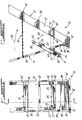
- Figure 1 is a side elevational sectional view of a stepladder according to a first embodiment of the present invention;
- Figure 2 is a front elevational view of the stepladder of Figure 1;
- Figure 3 is a side sectional view taken along line 3-3 of Figure 2;
- Figure 4 is a sectional view taken along line 4-4 of Figure 3;
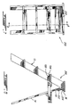
- Figure 5 is a front elevational view of a stepladder according to a second embodiment of the present invention;
- Figure 6 is a sectional view taken along line 6-6 of Figure 5;
- Figure 7 is a front elevational view of a stepladder according to a third embodiment of the present invention; and
- Figure 8 is a sectional view taken along line 8-8 of Figure 7.
- Referring to Figures 1-4 of the appended drawings, a
stepladder 10 according to a first embodiment of the present invention will be described. - The
stepladder 10 consists of aload bearing section 12, asupport section 14, abracing shelf 16 and achain 18. - The
load bearing section 12 comprises first and second spaced apartlegs intermediary steps legs top step 30 is also mounted at respectiveupper ends second legs load bearing section 12 also includes atransversal member 36 fixedly mounted to thetop step 30 and to the first andsecond legs transversal member 36 will be explained hereinafter. - The
stepladder 10 is illustrated in Figures 1-4 as having threesteps - The
step 28 includes aninner edge 29 and anundersurface 31. A pair ofspacing blocks undersurface 31 of thestep 28, and a pair oflocking members spacing blocks spacing blocks locking members - The
support section 14 includes first and second spaced apartlegs transversal members legs - As shown in Figures 1 and 3, the
support section 14 is hindgedly mounted to theload bearing section 12. A pair ofhinges transversal member 44 of thesupport section 14 and thetransversal member 36 of theload bearing section 12. Thesupport section 14 may therefore be alternatively positioned in an open position in which they define an angle (illustrated in Figure 1) or in a closed position (not shown), in which theload bearing section 12 and thesupport section 14 are in a substantially parallel relationship. - The
chain 18 is provided to limit the opening of thesupport section 14 when thestepladder 10 is in an open position. Indeed, the length of thechain 18 is such that a predetermined angle is defined by theload bearing section 12 and thesupport section 14 when thechain 18 is under tension. Thechain 18 is mounted between thelower step 24 of theload bearing section 12 and the firsttransversal member 42 of thesupport section 14. - The
bracing shelf 16 includes first and second spaced apartarms shelf panel 54 and first and secondtransversal spacers arm surface 59 and an abutting member 60 (only one being shown) having aninner edge 62. - The first and
second spacers second arms second arms shelf panel 54 is fixedly mounted over the first andsecond arms bracing shelf 16 is pivotally mounted to thesupport section 14 through a pair of D-shaped brackets 64 (only one being shown). Each D-shapedbracket 64 is fixedly mounted to one of thelegs support section 14. As illustrated, eacharm shelf 16 is pivotally mounted to one of the first andsecond legs support section 14. - The bracing
shelf 16 may therefore be pivoted between a retracted position illustrated in full lines in Figure 1 or a bracing position illustrated in dashed lines in Figure 1 and in full lines in Figure 3. When the bracingshelf 16 is in the bracing position, the contactingsurface 59 of thearms undersurface 31 of thestep 28. - In operation, when the bracing
shelf 16 is in the position illustrated in dashed lines in Figure 1, theinner edges 62 of the abuttingpieces 60 are in contact with theinner edge 29 of thestep 28. Therefore, when the bracingshelf 16 is in the position illustrated in dashed lines, it is not possible to move thesupport section 14 in the direction illustrated byarrow 66, e.g., to bring thesupport section 14 in a closed position, without first pivoting the bracingshelf 16 in the direction illustrated byarrow 68 since the contact of theinner edges 62 of the abuttingpieces 60 and theinner edge 29 ofstep 28 prevents the pivoting, in the direction ofarrows 66, of thesupport section 14 abouthinges - Furthermore, when the bracing
shelf 16 is in the position illustrated in dashed lines in Figure 1, it is possible to pivotally engage the locking blocks 37, 39 so that a portion of each lockingblock arms shelf 16. This position of the locking blocks 37, 39 is illustrated in Figures 3 and, in more details, in Figure 4. - Therefore, when the
stepladder 10 is in the position of Figure 3, it is not possible to pivot the bracingshelf 16 in the direction of arrow 68 (see Figure 1) without first rotating the locking blocks 37, 39 so that they do not lie over thearms shelf 16. - As will be evident to one of ordinary skills in the art, if the material used to form the different sections of the
stepladder 10 is sufficiently strong, theshelf panel 54 of the bracingshelf 16 may be used as a step without the drawbacks discussed above. As non limitative examples, thestepladder 10 could be made of wood, aluminium, plastic, synthetic resin, reinforced fibreglass, etc. - Turning now to Figures 5-6, a
stepladder 100, according to a second embodiment of the present invention, will be described. -
Stepladder 100 is very similar tostepladder 10 illustrated in Figures 1 to 4. Accordingly, only the differences betweenstepladders - The
chain 18 has been eliminated fromstepladder 100. To limit the angle defined by theload bearing portion 12 and thesupport section 14, an abuttingmember 102 is fixedly mounted at a specific location to theundersurface 31 of thestep 28. The abuttingmember 102 is mounted so as to be in contact with the spacingmember 58 when the bracingshelf 16 is in the position of Figure 6. The abuttingmember 102 therefore prevents further opening of thesupport section 14 with respect to theload bearing section 12. It is to be noted that this position of the abuttingmember 102 does not impede the pivotal movements of the bracingshelf 16 about thesupport section 14 as previously discussed. - A
manual latching mechanism 104 is mounted to theundersurface 31 of thestep 28. Thelatch mechanism 104 is adapted to latch to ablock 106 mounted to thetransversal spacer 58. The function of thelatch mechanism 104 is similar to that of the lockingmembers latch mechanism 104 over the lockingmembers shelf 16 reaches the position illustrated in Figure 6. Furthermore, the latch mechanism may be easily manually disengaged. It is to be noted that various latch mechanisms are commercially available and could be used as previously described. - A
small chain 108 is mounted between thetop step 30 and the secondtransversal member 44 of thesupport assembly 14. Thechain 108 is provided only to help the user to position the support section in an appropriate angle before one attempts to pivot and latch the bracingshelf 16 in the bracing position illustrated in Figure 6. Thechain 108 is not used to limit the angle between thesupport section 14 and theload bearing section 12 while thestepladder 100 is used. - Turning now to Figures 7-8, a
stepladder 200, according to a third embodiment of the present invention, will be described. -
Stepladder 200 is similar tostepladders stepladder 200 andstepladders - While
stepladder 100 include both thelatch mechanism 104 and the lockingmembers stepladder 200 only includes thelatch mechanism 104 and thecorresponding block 106. Indeed, it has been found that, if thelatch mechanism 104 and theblock 106 are solidly built (for example if they are made of solid metallic parts), the lockingmembers - The
small chain 108 ofstepladder 100 has been replaced by an angled abutting block 202 fixedly mounted to the second transversal member of thesupport section 14. Theabutting block 202 includes anangled edge 204 adapted to contact thetransversal member 26 of theload bearing section 12 when thesupport section 14 reaches an appropriate angle with respect to theload bearing section 12. Again, block 202 is provided only to help the user to position the support section in an appropriate angle before one attempts to pivot and latch the bracingshelf 16 in the bracing position illustrated in Figure 8. Theblock 202 is not used to limit the angle between thesupport section 14 and theload bearing section 12 while thestepladder 200 is used. - Although the present invention has been described hereinabove by way of preferred embodiments thereof, it can be modified at will, within the scope of the appended claims, without departing from the spirit and nature of the subject invention.
Claims (20)
- A stepladder comprising:a load bearing section including first and second spaced apart legs and a plurality of steps extending between said first and second legs; each said step having a top surface for stepping thereon, an undersurface, a front edge and a rear edge;a support section hingedly connected to said load bearing section for pivotable movements about a first axis between (i) an open position in which said load bearing section and said support section define an angle, and (ii) a closed position in which said load bearing section and said support section are generally parallel;means for limiting said angle defined by said load bearing section and said support section when said support section is in said open position;a bracing shelf pivotally mounted to said support section for pivotable movements, about a second axis parallel to said first axis, between a bracing position and a retracted position; said bracing shelf having an inner projecting portion adapted to rest in interlocking engagement with of one of said plurality of steps when (a) said support section is in said open position, and (b) said bracing shelf is in said bracing position; said interlocking engagement between said inner projecting portion and one of said steps of said load bearing section being such that said support section is prevented from pivoting to said closed position when said bracing shelf is in said bracing position.
- A stepladder as defined in claim 1, wherein said interlocking engagement is provided between said inner projecting portion of said bracing shelf and said undersurface of said one of said steps.
- A stepladder as defined in claim 2, wherein said interlocking engagement is further provided between said inner projecting portion of said bracing shelf and said rear edge of said one of said steps.
- A stepladder as defined in claim 3, wherein said bracing shelf further comprises an outer projecting step/shelf panel portion having a top surface.
- A stepladder as defined in claim 4, wherein said inner projecting portion comprises first and second spaced apart arms each having a top surface and an undersurface.
- A stepladder as defined in claim 5, wherein each said top surface of said first and second spaced apart arms is adapted to frictionally engage said undersurface of said one of said steps when said bracing shelf is in said bracing position.
- A stepladder as defined in claim 6, wherein each said first and second spaced apart arms has an abutting member adapted to frictionally engage said rear edge of said one of said steps when said bracing shelf is in said bracing position.
- A stepladder as defined in claim 7, further comprising means for positively and releasably locking said bracing shelf in said bracing position.
- A stepladder as defined in claim 8, wherein said means for positively and releasably locking said bracing shelf in said bracing position includes a locking mechanism for positively and releasably maintaining said inner projecting portion of said bracing shelf and said one of said steps in said interlocking engagement.
- A stepladder as defined in claim 9, wherein said locking mechanism comprises:at least one spacing block mounted to said undersurface of said one of said steps; said at least one spacing block having an undersurface;at least one moveable locking element mounted to said undersurface of said at least one spacing block for movement between a locking position and a releasing position; said at least one moveable block having a contact surface for contacting said undersurface of one of said first and second spaced apart arms when (a) said first and second arms are in said interlocking engagement with said one of said steps, and (b) when said at least one spacing block is in said locking position.
- A stepladder as defined in claim 9, wherein said locking mechanism comprises a manually releasable catch mounted to said undersurface of said one of said steps; said manually releasable catch being adapted to contact said inner projecting portion of said bracing shelf to thereby positively and releasably maintain said inner projecting portion of said bracing shelf and said undersurface of said one of said steps in said interlocking engagement.
- A stepladder as defined in claim 11, wherein said means for limiting said angle defined by said load bearing section and said support section when said support section is in said open position comprise a flexible member having a given length and secured between said load bearing section and said supporting section.
- A stepladder as defined in claim 11, wherein said means for limiting said angle defined by said load bearing section and said support section when said support section is in said open position comprise an abutting block mounted to said undersurface of said one of said steps, said abutting block being adapted to contact said inner projecting portion of said bracing shelf in an interlocking engagement; said abutting block preventing further opening of said support section when said bracing shelf is in said bracing position.
- A stepladder as defined in claim 1, further comprising means for positively and releasably locking said bracing shelf in said bracing position.
- A stepladder as defined in claim 14, wherein said means for positively and releasably locking said bracing shelf in said bracing position includes a locking mechanism for positively and releasably maintaining said inner projecting portion of said bracing shelf and said one of said steps in said interlocking engagement.
- A stepladder as defined in claim 1, wherein said means for limiting said angle defined by said load bearing section and said support section when said support section is in said open position comprise a flexible member having a given length and secured between said load bearing section and said supporting section.
- A stepladder comprising:a load bearing section including first and second spaced apart legs and a plurality of steps extending between said first and second legs; each said step having a top surface for stepping thereon, an undersurface, a front edge and a rear edge;a support section hingedly connected to said load bearing section for pivotable movements about a first axis between (i) an open position in which said load bearing section and said support section define an angle, and (ii) a closed position in which said load bearing section and said support section are generally parallel;a bracing shelf pivotally mounted to said support section for pivotable movements, about a second axis parallel to said first axis, between a bracing position and a retracted position; said bracing shelf having an inner projecting portion adapted to rest in interlocking engagement with of one of said plurality of steps when (a) said support section is in said open position, and (b) said bracing shelf is in said bracing position said interlocking engagement between said inner projecting portion and one of said steps of said load bearing section so as to prevent further movements of said support section with respect to said bracing section.
- A stepladder as defined in claim 17, wherein said bracing shelf comprise an outer projecting step/tool tray portion, a first and a second spaced apart arms each having a top surface, an undersurface and an abutting piece, each said top surface of said first and second arms being adapted to frictionally engage the undersurface of said one of said steps, each said abutting piece of said first and second arms being adapted to frictionally engage said rear edge of said one of said steps so as to prevent said support section from pivoting in said closed position, said inner projecting portion of said bracing shelf also includes a transversal member adapted to frictionally engage said undersurface of said one of said steps so as to prevent further opening of the support section with respect to the load bearing section.
- A stepladder as defined in claim 18, further comprising means for positively and releasably locking said bracing shelf in said bracing position.
- A stepladder as defined in claim 19, wherein said means for positively and releasably locking said bracing shelf in said bracing position comprise a manually releasable catch mounted to said undersurface of said one of said steps; said manually releasable catch being adapted to contact said inner projecting portion of said bracing shelf to thereby positively and releasably maintain said inner projecting portion of said bracing shelf and said undersurface of said one of said steps in said interlocking engagement.
Applications Claiming Priority (3)
| Application Number | Priority Date | Filing Date | Title |
|---|---|---|---|
| CA2162827 | 1995-11-14 | ||
| CA002162827A CA2162827A1 (en) | 1995-11-14 | 1995-11-14 | Stepladder including a bracing shelf |
| US08/559,635 US5715909A (en) | 1995-11-14 | 1995-11-20 | Stepladder including a bracing shelf |
Publications (1)
| Publication Number | Publication Date |
|---|---|
| EP0774562A1 true EP0774562A1 (en) | 1997-05-21 |
Family
ID=25678217
Family Applications (1)
| Application Number | Title | Priority Date | Filing Date |
|---|---|---|---|
| EP96402438A Withdrawn EP0774562A1 (en) | 1995-11-14 | 1996-11-14 | Stepladder including a bracing shelf |
Country Status (3)
| Country | Link |
|---|---|
| US (1) | US5715909A (en) |
| EP (1) | EP0774562A1 (en) |
| CA (1) | CA2162827A1 (en) |
Cited By (1)
| Publication number | Priority date | Publication date | Assignee | Title |
|---|---|---|---|---|
| EP3524768A1 (en) | 2018-02-07 | 2019-08-14 | Hailo-Werk Rudolf Loh GmbH & Co. KG | Step ladder, in particular step ladder with treads |
Families Citing this family (7)
| Publication number | Priority date | Publication date | Assignee | Title |
|---|---|---|---|---|
| US6986405B2 (en) * | 2003-07-21 | 2006-01-17 | Cosco Management, Inc. | Ladder with leg brace |
| US7984790B2 (en) * | 2006-06-07 | 2011-07-26 | Cosco Management, Inc. | Folding tray for foldable step stool |
| US9534443B1 (en) | 2011-12-27 | 2017-01-03 | Robert C. Bogart | Ladder and related methods |
| US8925684B1 (en) * | 2012-11-07 | 2015-01-06 | Michael Frank Medina | Ladder shelf system |
| US9765570B2 (en) * | 2014-07-14 | 2017-09-19 | Otten & Otten Construction Limited | Brace for step ladder |
| CN114466965A (en) | 2019-09-18 | 2022-05-10 | 稳耐公司 | Human-shaped ladder pivot and locking mechanism |
| AU2021205029B2 (en) | 2020-07-22 | 2023-04-13 | Werner Co. | Multi-Position Ladder, Method of Using and Method of Making a Multi-Position Ladder |
Citations (5)
| Publication number | Priority date | Publication date | Assignee | Title |
|---|---|---|---|---|
| US1500937A (en) * | 1923-12-13 | 1924-07-08 | George F Hotopp | Knockdown stepladder |
| GB401931A (en) * | 1933-02-15 | 1933-11-23 | John Lyon | Improvements relating to portable steps |
| US1992391A (en) * | 1933-09-08 | 1935-02-26 | F B Pease Company | Stepladder |
| US2639853A (en) * | 1947-12-05 | 1953-05-26 | Robert E Pierce | Ladder structure |
| GB906650A (en) * | 1959-10-21 | 1962-09-26 | Robinson & Sons Ltd | An improved tripod ladder |
Family Cites Families (10)
| Publication number | Priority date | Publication date | Assignee | Title |
|---|---|---|---|---|
| CA642101A (en) * | 1962-06-05 | J. Ruggieri Anthony | Step ladder attachment | |
| US712351A (en) * | 1900-10-26 | 1902-10-28 | Selah S W Westover | Step-ladder. |
| US1113436A (en) * | 1914-03-10 | 1914-10-13 | Aaron Hartzler | Ladder. |
| US2007713A (en) * | 1933-09-09 | 1935-07-09 | Herman B Gaffers | Brace for ladders |
| US2481581A (en) * | 1945-12-17 | 1949-09-13 | Ehnhuus Hartvig | Extension stepladder |
| US4079814A (en) * | 1977-03-09 | 1978-03-21 | White Metal Rolling & Stamping Corporation | Stepladders |
| US4718518A (en) * | 1986-11-17 | 1988-01-12 | Brown William E | Step ladder |
| US4834216A (en) * | 1987-01-15 | 1989-05-30 | Emerson Electric Co. | Foldable ladder structure and method of manufacturing the same |
| US5098052A (en) * | 1991-06-06 | 1992-03-24 | Beck Daniel L | magnetic support tray for ladder shelf |
| US5421429A (en) * | 1994-05-04 | 1995-06-06 | Evans; John | Ladder with safety feet |
-
1995
- 1995-11-14 CA CA002162827A patent/CA2162827A1/en not_active Abandoned
- 1995-11-20 US US08/559,635 patent/US5715909A/en not_active Expired - Fee Related
-
1996
- 1996-11-14 EP EP96402438A patent/EP0774562A1/en not_active Withdrawn
Patent Citations (5)
| Publication number | Priority date | Publication date | Assignee | Title |
|---|---|---|---|---|
| US1500937A (en) * | 1923-12-13 | 1924-07-08 | George F Hotopp | Knockdown stepladder |
| GB401931A (en) * | 1933-02-15 | 1933-11-23 | John Lyon | Improvements relating to portable steps |
| US1992391A (en) * | 1933-09-08 | 1935-02-26 | F B Pease Company | Stepladder |
| US2639853A (en) * | 1947-12-05 | 1953-05-26 | Robert E Pierce | Ladder structure |
| GB906650A (en) * | 1959-10-21 | 1962-09-26 | Robinson & Sons Ltd | An improved tripod ladder |
Cited By (1)
| Publication number | Priority date | Publication date | Assignee | Title |
|---|---|---|---|---|
| EP3524768A1 (en) | 2018-02-07 | 2019-08-14 | Hailo-Werk Rudolf Loh GmbH & Co. KG | Step ladder, in particular step ladder with treads |
Also Published As
| Publication number | Publication date |
|---|---|
| CA2162827A1 (en) | 1997-05-15 |
| US5715909A (en) | 1998-02-10 |
Similar Documents
| Publication | Publication Date | Title |
|---|---|---|
| US6347483B1 (en) | Child safety barrier | |
| US5005223A (en) | Foldable toilet seat | |
| US11312285B2 (en) | Tailgate with integrated loading ramp system | |
| US5882030A (en) | Stroller handlebar | |
| US4746141A (en) | Door carrier | |
| JP4197758B2 (en) | Improved keyboard support mechanism | |
| EP0774562A1 (en) | Stepladder including a bracing shelf | |
| US4901261A (en) | Retractable handle and latch for portable computers | |
| US4843680A (en) | Hinge particularly adapted for use with a false cabinet front | |
| US4506928A (en) | Baby chair | |
| US4913394A (en) | Article holding tray assembly for ladder | |
| CA2246073C (en) | Clamping mechanism for keyboard support | |
| US3245715A (en) | Molded articles and methods of making same | |
| US4620613A (en) | Self-closing saw horse | |
| JP2688767B2 (en) | Ironing board assembly | |
| HU192264B (en) | Hinge device for balance windows | |
| US4120249A (en) | Folding table equipped with improved latch mechanism that holds table top sections coplanar and prevents accidental injury during unfolding | |
| KR870004688A (en) | Folding table | |
| US3331577A (en) | Article support for a ladder | |
| US4686742A (en) | Auxiliary handle for a door | |
| US5664817A (en) | Portable door stop | |
| GB2036152A (en) | Ladder platform | |
| NL1008293C2 (en) | Folding ironing table. | |
| WO1995030586A1 (en) | Torsional linkage for controlling movement of a gate or panel of a collapsible container | |
| JP3591452B2 (en) | Horizontal stacking table |
Legal Events
| Date | Code | Title | Description |
|---|---|---|---|
| PUAI | Public reference made under article 153(3) epc to a published international application that has entered the european phase |
Free format text: ORIGINAL CODE: 0009012 |
|
| AK | Designated contracting states |
Kind code of ref document: A1 Designated state(s): AT BE CH DE DK ES FI FR GB GR IE IT LI LU MC NL PT SE |
|
| AX | Request for extension of the european patent |
Free format text: AL;LT;LV;RO;SI |
|
| STAA | Information on the status of an ep patent application or granted ep patent |
Free format text: STATUS: THE APPLICATION IS DEEMED TO BE WITHDRAWN |
|
| 18D | Application deemed to be withdrawn |
Effective date: 19971122 |