EP0776129B1 - Appareil pour la transmission/réception d'un signal de référence de suppression d'image fantôme dans un signal de télévision PAL - Google Patents
Appareil pour la transmission/réception d'un signal de référence de suppression d'image fantôme dans un signal de télévision PAL Download PDFInfo
- Publication number
- EP0776129B1 EP0776129B1 EP96307398A EP96307398A EP0776129B1 EP 0776129 B1 EP0776129 B1 EP 0776129B1 EP 96307398 A EP96307398 A EP 96307398A EP 96307398 A EP96307398 A EP 96307398A EP 0776129 B1 EP0776129 B1 EP 0776129B1
- Authority
- EP
- European Patent Office
- Prior art keywords
- ghost
- reference signal
- signal
- canceling reference
- transmitting
- Prior art date
- Legal status (The legal status is an assumption and is not a legal conclusion. Google has not performed a legal analysis and makes no representation as to the accuracy of the status listed.)
- Expired - Lifetime
Links
- 230000004044 response Effects 0.000 claims description 5
- 230000037431 insertion Effects 0.000 claims 2
- 238000003780 insertion Methods 0.000 claims 2
- 238000010586 diagram Methods 0.000 description 10
- 230000000694 effects Effects 0.000 description 3
- NJPPVKZQTLUDBO-UHFFFAOYSA-N novaluron Chemical compound C1=C(Cl)C(OC(F)(F)C(OC(F)(F)F)F)=CC=C1NC(=O)NC(=O)C1=C(F)C=CC=C1F NJPPVKZQTLUDBO-UHFFFAOYSA-N 0.000 description 3
- 238000000034 method Methods 0.000 description 2
- 230000005540 biological transmission Effects 0.000 description 1
- 238000009877 rendering Methods 0.000 description 1
Images


Classifications
-
- H—ELECTRICITY
- H04—ELECTRIC COMMUNICATION TECHNIQUE
- H04N—PICTORIAL COMMUNICATION, e.g. TELEVISION
- H04N5/00—Details of television systems
- H04N5/14—Picture signal circuitry for video frequency region
- H04N5/21—Circuitry for suppressing or minimising disturbance, e.g. moiré or halo
-
- H—ELECTRICITY
- H04—ELECTRIC COMMUNICATION TECHNIQUE
- H04N—PICTORIAL COMMUNICATION, e.g. TELEVISION
- H04N5/00—Details of television systems
- H04N5/14—Picture signal circuitry for video frequency region
- H04N5/21—Circuitry for suppressing or minimising disturbance, e.g. moiré or halo
- H04N5/211—Ghost signal cancellation
Definitions
- the present invention relates to the PAL TV system that is mostly used in Europe, China and East Asia, and more particularly, to apparatus for transmitting/receiving a ghost canceling reference (GCR) signal in PAL TV in which a GCR signal is produced by a ternary sequence at a transmitting port, thereby canceling a ghost produced by characteristics of a transmitting channel at the receiving port using the GCR signal.
- GCR ghost canceling reference
- a signal received at the receiving port contains a ghost produced by a signal transmitted to the transmitting port.
- NTSC TV cancels it at the receiving port, using a ternary sequence GCR signal with high energy and correlation gain which is transmitted at the transmitting port to a vertical blanking interval (VBI) of a TV signal.
- VBI vertical blanking interval
- the conventional ghost canceling apparatus is used only for the NTSC mode in canceling the ghost.
- the PAL mode does not transmit the GCR signal so that it is hard to cancel the ghost in a TV receiver of PAL mode.
- Preferred embodiments of the present invention seek to address the problems of the prior art, and it is a main object of these embodiments to provide apparatus for transmitting/receiving a GCR signal in the PAL mode, which transmits a ternary sequence GCR signal to a certain line inside VBI of every even field in the PAL mode, thereby cancelling the ghost at the receiving port.
- the invention provides an apparatus for transmitting a ghost-cancelling reference signal in a TV system as set out in Claim 1 and a corresponding apparatus for receiving as set out in Claim 14.
- the apparatus for transmitting/receiving ghost-canceling reference signal is comprised of a GCR signal generating portion 10 and GCR signal inserting portion 20.
- GCR signal generating portion 10 detects vertical and horizontal sync signals Vsync and Hsync from a broadcasting signal, catches a certain line on which a ternary sequence GCR signal will be loaded, from the broadcasting signal, and finally loads the waveform of the ternary sequence GCR signal on the certain line caught.
- the GCR signal inserting portion 20 selects the ternary sequence GCR signal produced from the GCR signal generating portion 10, only in the certain caught line, and selects and outputs a program to be broadcast in other lines.
- GCR signal generating portion 10 is composed of a read only memory (ROM) 11 for storing the ternary sequence GCR signal of positive and negative polarities, a counter 12 for controlling the output of ROM 11, a digital/analog converter 13 for converting ROM 11's output signal into an analog signal, a sync detector 14 for detecting vertical and horizontal sync signals Vsync and Hsync from a broadcasting program signal, and a controller 15 for detecting a certain line where the ternary sequence GCR signal is loaded, from the output of sync detector 14, to thereby output a switching controlling signal S1.
- ROM read only memory
- a counter 12 for controlling the output of ROM 11
- a digital/analog converter 13 for converting ROM 11's output signal into an analog signal
- a sync detector 14 for detecting vertical and horizontal sync signals Vsync and Hsync from a broadcasting program signal
- a controller 15 for detecting a certain line where the ternary sequence GCR signal
- Ghost canceling signal inserting portion 20 is composed of a 2:1 multiplexer or an analog switch which selectively outputs the output of digital/analog converter 13 or the output of the broadcasting program according to switching control signal S1 of controller 15.
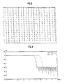
- the ghost canceling reference signal transmitting apparatus produces a 494-long ternary sequence GCR signal from a 366-long ternary sequence, using a low-pass filter having frequency characteristics of FIG. 4.
- the original length of the ternary sequence is 183. However, this length becomes 366 by inserting 0 for every sample so that interference between symbols is reduced.
- the full line of FIG. 4 is indicated to produce a PAL B&G (for European) GCR signal whose cut-off frequency is 5MHz, whereas the dotted line is to produce a PAL D&K (for Chinese) GCR signal whose cut-off frequency is 6MHz.
- FIG. 5 shows the ternary sequence GCR signal of positive and negative polarities attained using the ternary sequence of FIG. 3 and the low-pass filter having frequency characteristics of FIG. 4.
- FIGS. 5A and 5B show GCR signal waveforms of positive and negative polarities for PAL B&G, respectively,
- FIGS. 5C and 5D showing GCR signal waveforms of positive and negative polarities for PAL D&K, respectively.
- FIGS. 5A-5D are signal waveforms attained by amplitude-scaling the ternary sequence GCR signal passing through the low-pass filter with characteristics of FIG. 4.
- the ternary sequence GCR signal to be used is converted into signal waveforms like FIGS. 5A-5D through low-pass filter 31 with frequency characteristics of FIG. 4 and through amplitude scaling portion 32 which amplitude-scales the output of low-pass filter 31, as shown in FIG. 6.
- the ternary sequence GCR signal attained by the ternary sequence passing through low-pass filter 31 and amplitude scaling portion 32 as above is stored in ROM 11 shown in FIG. 2A, 2B or 2C.
- the output of ROM 11 is output as an analog signal sequentially through digital/analog converter 13 according to a counter 12.
- controller 15 From vertical and horizontal sync signals Vsync and Hsync detected from sync detector 14, controller 15 senses a certain line on which the ternary sequence GCR signal will be loaded to thereby control switching of the multiplexer of GCR signal inserting portion 20. In this state, the ternary sequence GCR signal is inserted into a certain line of a broadcasting program, and transmitted through a transmitting port.
- the ternary sequence GCR signal is transmitted by an 8 field transmitting sequence as shown in Table 1 below (since one period of signal is eight fields in the PAL TV, whereas the period is four fields in the NTSC TV).
- the GCR signal is loaded on one certain line (line 318, for example) of VBI of every even field because the waveforms within the VBI of even and odd fields are different in the PAL TV. TABLE 1.
- the GCR signal of positive polarity (+) is sent.
- the GCR signal of negative polarity (-) is sent. That is, the polarity of the GCR signal is inverted for every frame; to improve its signal-to-noise (S/N) ratio and also cancel a sync and color burst at the receiving port. As a result, only the GCR signal is obtained.
- the polarity of the GCR signal becomes different in transmitting signals of the second field F2 and fourth field F4, as shown in FIG. 7 so that the sync and color burst are canceled and the amplitude of the GCR signal is doubled by subtracting the signals of the second and fourth fields. This finally improves the SIN ratio.
- FIG. 2B shows another embodiment of GCR signal generating portion 10 which is comprised of a read only memory (ROM) 11 for storing the GCR signal of positive and negative polarities, a counter 12 for controlling the output of ROM 11, a digital/analog converter 13 for converting ROM 11's output signal to an analog, a sync detector 14 for detecting vertical and horizontal signals Vsync and Hsync from the broadcasting program signal, and a certain line detector 16 for outputting switching controlling signal S1 by detecting a certain line on which the ternary sequence GCR signal is to be loaded, from the output of sync detector 14.
- the operation of this embodiment is the same as that of the first embodiment so that the effects concerned will be omitted.
- GCR signal generating portion 10 attains the GCR signal of positive and negative polarities by storing only the GCR signal of positive and negative polarities in ROM 11 and additionally providing a -1 multiplier 17 at the output port of digital/analog converter 13 for multiplying -1.
- the -1 multiplier inverts the output of ROM 11. In this case, the capacity of ROM 11 can be reduced.
- Controller 15 should be constructed to control the multiplying operation of multiplier 17. For example, in case that only the GCR signal of positive polarity is stored in ROM 11, in order to attain the GCR signal of negative polarity, it must be multiplied by -1 in multiplier 17. In order to output the GCR signal of positive polarity, it must not be multiplied by -1 in multiplier 17.
- FIG. 8 shows a block diagram of the receiving block of the PAL TV ghost-canceling reference signal transmitting/receiving apparatus which is composed of an analog/digital converter 41 for converting a baseband broadcasting signal input into a digital signal, a sync separator 42 for separating its sync signal from the baseband broadcasting signal input, a GCR signal storage 43 where the same GCR signal is stored as that stored in ROM 11 of the transmitting block, a digital filter 44 for canceling the ghost of the output of analog/digital converter 41 produced due to characteristics of the transmitting channel, an operating portion 45 for catching a line on which the GCR signal is loaded, from the output of sync separator 42, and subtracting as many as a predetermined number to thereby attain the GCR signal free from its sync signal and color burst and with an SIN ratio improved as well, and finally comparing the resultant GCR signal with the signal of GCR signal storage 43 to obtain a filter coefficient of digital filter 44 needed in canceling the ghost produced due to characteristics of the transmitting channel
- the digital filter 44 is composed of a finite impulse response (FIR) And an infinite impulse response (IIR).
- analog/digital converter 41 converts, into a digital signal, an analog signal input as a baseband signal into which the GCR signal transmitted from a broadcasting station as stated before is converted via a tuner and intermediate frequency demodulating port (not shown).
- the converted digital signal is output to a digital filter 44.
- the sync separator 42 separates a sync signal from the baseband broadcasting signal input to thereby output a separated sync signal to operating portion 45. Sequentially, operating portion 45 catches a line on which the ternary sequence GCR signal is put, using the sync signal attained from sync separator 42 and subtracts by a predetermined number to thereby attain a GCR signal with its sync signal and color burst canceled and an S/N ratio improved.
- the operating portion 45 performs subtraction in groups by 8, 16 or 32 fields because the characteristics of the transmitting channel may be changed over time when too many fields are subtracted. For example, if field 4 (F4) is subtracted from field 2 (F2), in other words, when the average is taken by subtracting them, only a GCR signal free from sync signal and color burst is produced as shown in FIG 9.
- This GCR signal includes ghost signal (a) produced by the characteristics of the transmitting channel.
- a ghost signal a remaining after subtraction in operating portion 45 is canceled by digital filter 44.
- a ghost signal (a) is canceled upon comparing the GCR signal attained by subtraction in operating portion 45 with that stored in GCR signal storage 50, thereby non-real-time obtaining a coefficient of digital filter 44 needed in canceling the ghost produced due to characteristics of a transmitting channel, and then applying the coefficient to digital filter 44.
- a signal shown in FIG. 11B is obtained by letting the signal, which is attained through the aforementioned subtraction and shown in FIG. 11A, pass through a c7eiav (Z -10 ) and then a -0.1 multiplier.
- the secondary and third ghosts are successively produced via the FIR filter. However, they can be completely canceled by the IIR filter composed of a filter coefficient attained from operating portion 45. A detailed explanation will be omitted because its principle is general.
- the coefficient of digital filter 44 attained from operating portion 45 is downloaded to digital filter 44 during VBI, in order not to cause any effects on a picture. From this point on, a signal free from ghost is output from digital/analog converter 46 in real time.
- a 366-long ternary sequence is used.
- a ternary sequence GCR signal used currently in NTSC mode may be adapted to PAL mode so that a ghost produced due to the characteristics of a transmitting channel is completely canceled even in PAL mode.
- those embodiments use a GCR signal made with a ternary sequence, rendering its energy and correlation gain higher.
- the described embodiments are capable of canceling ghosts at high speed through correlative operation because the transmission occupying line of the GCR signal is one line within a vertical blanking interval, and a ternary sequence GCR signal composed of elements 1, 0, and -1 is used.
- the GCR signal transmitting/receiving apparatus described is usefully adaptable to PAL TVs, VCRs and set-top boxes.
Landscapes
- Engineering & Computer Science (AREA)
- Multimedia (AREA)
- Signal Processing (AREA)
- Picture Signal Circuits (AREA)
Claims (22)
- Appareil pour l'émission d'un signal de référence supprimant l'image fantôme dans un système de télévision, ledit appareil comportant :un moyen d'émission (10, 20) destiné à charger un signal de référence supprimant l'image fantôme de séquence ternaire sur une certaine ligne d'un signal de diffusion et à émettre ainsi le résultat du chargement ;caractérisé en ce que ledit système de télévision est un système de télévision PAL et ledit moyen d'émission est conçu pour produire ladite séquence ternaire étendue à 366 symboles par l'insertion d'un zéro pour chaque échantillon.
- Appareil pour l'émission d'un signal de référence supprimant l'image fantôme dans un système de télévision PAL selon la revendication 1, dans lequel ledit signal de référence supprimant l'image fantôme de séquence ternaire est obtenu en faisant passer une séquence ternaire à travers un filtre passe-bas (31) puis en soumettant son amplitude à une mise à l'échelle dans une partie (32) de mise à l'échelle de l'amplitude.
- Appareil pour l'émission d'un signal de référence supprimant l'image fantôme dans un système de télévision PAL selon la revendication 2, dans lequel la fréquence de coupure du filtre passe-bas est de 5 MHz dans un mode PAL B&G, et de 6 MHz dans un mode PAL D&K.
- Appareil pour l'émission d'un signal de référence supprimant l'image fantôme dans un système de télévision PAL selon la revendication 1, dans lequel ledit signal de référence supprimant l'image fantôme de séquence ternaire est chargé dans un intervalle de suppression verticale de chaque trame paire.
- Appareil pour l'émission d'un signal de référence supprimant l'image fantôme dans un système de télévision PAL selon la revendication 1, dans lequel ledit moyen d'émission émet ledit signal de référence supprimant l'image fantôme de séquence ternaire en l'inversant pour chaque image complète.
- Appareil pour l'émission d'un signal de référence supprimant l'image fantôme dans un système de télévision PAL selon la revendication 7, dans lequel ledit signal de référence supprimant l'image fantôme de séquence ternaire transmet un signal de référence supprimant l'image fantôme d'une polarité positive dans des deuxième et sixième trames et un signal de référence supprimant l'image fantôme de polarité négative dans des quatrième et huitième trames.
- Appareil pour l'émission d'un signal de référence supprimant l'image fantôme dans un système de télévision PAL selon la revendication 1, ledit appareil comportant :une partie (10) de génération d'un signal de référence supprimant l'image fantôme pour détecter des signaux de synchronisation verticale et horizontale à partir d'un signal de diffusion, accrocher une certaine ligne sur laquelle le signal de référence supprimant l'image fantôme de séquence ternaire sera chargé, à partir du signal du signal de diffusion, et charger enfin le signal de référence supprimant l'image fantôme de séquence ternaire sur ladite certaine ligne accrochée ; etune partie (20) d'insertion de signal de référence supprimant l'image fantôme pour, seulement dans ladite certaine ligne accrochée, sélectionner ledit signal de référence supprimant l'image fantôme de séquence ternaire produit à partir de ladite partie de génération de signal de référence supprimant l'image fantôme, dans d'autres lignes, ladite partie sélectionnant et émettant ledit signal de diffusion.
- Appareil pour l'émission d'un signal de référence supprimant l'image fantôme dans un système de télévision PAL selon la revendication 7, dans lequel ladite partie (10) de génération du signal de référence supprimant l'image fantôme est constituée de :une mémoire ROM (11) destinée à stocker ledit signal de référence supprimant l'image fantôme de séquence ternaire de polarités positive et négative ;un compteur (12) destiné à commander la sortie de ladite mémoire ROM ;un convertisseur numérique/analogique (13) destiné à convertir le signal de sortie de la mémoire ROM en un signal analogique ;un détecteur (14) de synchronisation destiné à détecter des signaux de synchronisation verticale et horizontale à partir dudit signal de diffusion.; etune unité de commande (15) destinée à détecter une certaine ligne où un signal de suppression d'image fantôme sera chargé, à partir du signal de sortie dudit détecteur de synchronisation, pour délivrer ainsi en sortie un signal de commande de commutation de ladite partie d'insertion du signal de référence supprimant l'image fantôme.
- Appareil pour l'émission d'un signal de référence supprimant l'image fantôme dans un système de télévision PAL selon la revendication 7, dans lequel ladite partie de génération du signal de référence supprimant l'image fantôme est constituée de :une mémoire ROM (11) destinée à stocker ledit signal de référence supprimant l'image fantôme de séquence ternaire de polarités positive et négative ;un compteur (12) destiné à commander la sortie de ladite mémoire ROM ;un convertisseur numérique/analogique (13) destiné à convertir le signal de sortie de la mémoire ROM en un signal analogique ;un détecteur (14) de synchronisation destiné à détecter des signaux de synchronisation verticale et horizontale à partir dudit signal de diffusion ; etun détecteur (16) d'une certaine ligne destiné à détecter une certaine ligne où ledit signal de référence supprimant l'image fantôme de séquence ternaire sera chargé, d'après le signal de sortie dudit détecteur de synchronisation, pour délivrer ainsi en sortie un signal de commande de commutation de ladite partie d'insertion de signal de référence supprimant l'image fantôme.
- Appareil pour l'émission d'un signal de référence supprimant l'image fantôme dans un système de télévision PAL selon la revendication 7, dans lequel ladite partie de génération du signal de référence supprimant l'image fantôme est constituée de :une mémoire ROM (11) destinée à stocker ledit signal de référence supprimant l'image fantôme de séquence ternaire de polarités positive et négative ;un compteur (12) destiné à commander la sortie de ladite mémoire ROM ;un convertisseur numérique/analogique (13) destiné à convertir le signal de sortie de la mémoire ROM en un signal analogique ;un multiplicateur (17) par -1 destiné à inverser sélectivement le signal de sortie dudit convertisseur numérique/analogique ;un détecteur (14) de synchronisation destiné à détecter des signaux de synchronisation verticale et horizontale à partir dudit signal de diffusion ; etune unité de commande (15) destinée à détecter une certaine ligne où ledit signal de référence supprimant l'image fantôme de séquence ternaire sera chargé, d'après le signal de sortie dudit détecteur de synchronisation, pour délivrer ainsi en sortie un signal de commande de multiplication dudit multiplicateur par -1 et un signal de commande de commutation.
- Appareil pour l'émission d'un signal de référence supprimant l'image fantôme dans un système de télévision PAL selon la revendication 7, dans lequel ladite partie d'insertion du signal de référence supprimant l'image fantôme est constituée d'un multiplexeur (20) pour délivrer sélectivement en sortie le signal de sortie dudit convertisseur numérique/analogique ou ledit signal de diffusion conformément à un signal de commande de commutation de ladite unité de commande.
- Appareil pour l'émission d'un signal de référence supprimant l'image fantôme dans un système de télévision PAL selon la revendication 7, dans lequel ladite partie d'insertion du signal de référence supprimant l'image fantôme est constituée d'un commutateur (20) destiné à délivrer sélectivement en sortie le signal de sortie dudit convertisseur numérique/analogique ou ledit signal de diffusion conformément à un signal de commande de commutation de ladite unité de commande.
- Appareil pour l'émission d'un signal de référence supprimant l'image fantôme dans un système de télévision PAL selon les revendications 1 à 12, ledit appareil comportant en outre :un moyen de réception destiné à supprimer une image fantôme produite par des caractéristiques d'un canal de transmission utilisant ledit signal de référence supprimant l'image fantôme de séquence ternaire transmis depuis ledit moyen d'émission.
- Appareil pour la réception d'un signal de diffusion de télévision PAL transmis par un canal de transmission, et la suppression d'une image fantôme produite par des caractéristiques du canal de transmission, comportant :un moyen (41, 42, 45) destiné à recevoir un signal de référence supprimant l'image fantôme de séquence ternaire chargé sur une certaine ligne du signal de diffusion,caractérisé en ce que l'appareil comporte en outre :une mémoire (43) de signal de référence supprimant l'image fantôme stockant un signal supprimant l'image fantôme de séquence ternaire émis, dans lequel ladite séquence ternaire est étendue à 366 symboles par l'insertion d'un zéro pour chaque échantillon ; etun moyen (44, 45) conçu pour supprimer l'image fantôme en utilisant le signal de référence supprimant l'image fantôme de séquence ternaire reçu, et le signal supprimant l'image fantôme de séquence ternaire émis.
- Appareil selon la revendication 14, dans lequel ledit signal de référence supprimant l'image fantôme de séquence ternaire reçu est chargé dans un intervalle de suppression verticale de chaque trame paire.
- Appareil selon la revendication 14, dans lequel le signal de référence supprimant l'image fantôme de séquence ternaire reçu est inversé pour chaque image complète.
- Appareil selon la revendication 16, dans lequel ledit signal de référence supprimant l'image fantôme reçu est d'une polarité positive dans des deuxième et sixième trames et d'une polarité négative dans des quatrième et huitième trames.
- Appareil selon la revendication 14, ledit appareil comportant en outre :un séparateur (42) de synchronisation destiné à séparer un signal de synchronisation d'une entrée de signal de diffusion de bande de base ;un filtre numérique (44) destiné à supprimer une image fantôme produite du fait de caractéristiques d'un canal de transmission depuis ladite entrée de signal de diffusion de bande de base ; etune partie de travail (45) destinée à accrocher une ligne où ledit signal de référence supprimant l'image fantôme de séquence ternaire est chargé, du signal de sortie dudit séparateur de synchronisation, de manière à obtenir ainsi ledit signal de référence supprimant l'image fantôme de séquence ternaire, puis à le comparer à un signal de ladite mémoire de signal de référence supprimant l'image fantôme, pour obtenir ainsi un coefficient dudit filtre numérique.
- Appareil selon la revendication 18, dans lequel ladite partie de travail (45) accroche une ligne pour chaque trame paire lorsque ledit signal de référence supprimant l'image fantôme de séquence ternaire est chargé, en utilisant ledit signal de synchronisation séparé dudit séparateur (42) de synchronisation, obtient un signal de référence supprimant l'image fantôme en effectuant des soustractions d'un nombre prédéterminé, puis compare ledit signal de référence supprimant l'image fantôme au signal de ladite mémoire de signal de référence supprimant l'image fantôme, pour obtenir ainsi un coefficient dudit filtre numérique nécessaire pour supprimer une image fantôme produite du fait de caractéristiques d'un canal de transmission.
- Appareil selon la revendication 19, dans lequel ladite soustraction est effectuée en groupes de 8, 16 ou 32 trames.
- Appareil selon la revendication 19, dans lequel ledit filtre numérique est constitué de :un filtre à réponse impulsionnelle finie destiné à supprimer une image fantôme proche de la porteuse ; etun filtre à réponse impulsionnelle finie destiné à supprimer une image fantôme éloignée.
- Appareil selon la revendication 19, dans lequel ledit moyen de réception comporte en outre :un convertisseur analogique/numérique (41) destiné à convertir en un signal numérique l'entrée du signal de diffusion de bande de base, et à le délivrer en sortie audit filtre numérique et à ladite partie de travail ; etun convertisseur analogique/numérique (46) destiné à convertir le signal de sortie dudit filtre numérique en un signal analogique.
Applications Claiming Priority (2)
| Application Number | Priority Date | Filing Date | Title |
|---|---|---|---|
| KR9542558 | 1995-11-21 | ||
| KR1019950042558A KR100390393B1 (ko) | 1995-11-21 | 1995-11-21 | 팔티브이(paltv)의고스트제거기준신호송수신장치 |
Publications (3)
| Publication Number | Publication Date |
|---|---|
| EP0776129A2 EP0776129A2 (fr) | 1997-05-28 |
| EP0776129A3 EP0776129A3 (fr) | 1999-05-26 |
| EP0776129B1 true EP0776129B1 (fr) | 2007-04-04 |
Family
ID=19434969
Family Applications (1)
| Application Number | Title | Priority Date | Filing Date |
|---|---|---|---|
| EP96307398A Expired - Lifetime EP0776129B1 (fr) | 1995-11-21 | 1996-10-10 | Appareil pour la transmission/réception d'un signal de référence de suppression d'image fantôme dans un signal de télévision PAL |
Country Status (6)
| Country | Link |
|---|---|
| EP (1) | EP0776129B1 (fr) |
| KR (1) | KR100390393B1 (fr) |
| CN (1) | CN1103158C (fr) |
| DE (1) | DE69637006D1 (fr) |
| MY (1) | MY127861A (fr) |
| SG (1) | SG46758A1 (fr) |
Family Cites Families (6)
| Publication number | Priority date | Publication date | Assignee | Title |
|---|---|---|---|---|
| JP2594639B2 (ja) * | 1989-03-23 | 1997-03-26 | 株式会社日立製作所 | テレビジョン映像受信信号波形歪み検出方法並びにそれに使用するテレビジョン映像信号送信装置および受信装置 |
| US5361102A (en) * | 1991-09-04 | 1994-11-01 | Samsung Electronics Co., Ltd. | System to cancel ghosts in NTSC television transmission |
| JPH05252423A (ja) * | 1992-03-06 | 1993-09-28 | Toshiba Corp | ゴースト除去装置 |
| US5363144A (en) * | 1992-04-16 | 1994-11-08 | Goldstar Co., Ltd. | Television ghost canceling device |
| US5309235A (en) * | 1992-09-25 | 1994-05-03 | Matsushita Electric Corporation Of America | System and method for transmitting digital data in the overscan portion of a video signal |
| JPH07203253A (ja) * | 1993-12-27 | 1995-08-04 | Toyota Central Res & Dev Lab Inc | テレビジョン受信機のゴースト除去装置 |
-
1995
- 1995-11-21 KR KR1019950042558A patent/KR100390393B1/ko not_active Expired - Fee Related
-
1996
- 1996-03-28 MY MYPI96001163A patent/MY127861A/en unknown
- 1996-04-25 CN CN96105170A patent/CN1103158C/zh not_active Expired - Fee Related
- 1996-10-10 DE DE69637006T patent/DE69637006D1/de not_active Expired - Lifetime
- 1996-10-10 EP EP96307398A patent/EP0776129B1/fr not_active Expired - Lifetime
- 1996-11-14 SG SG1996011108A patent/SG46758A1/en unknown
Also Published As
| Publication number | Publication date |
|---|---|
| SG46758A1 (en) | 1998-02-20 |
| EP0776129A3 (fr) | 1999-05-26 |
| DE69637006D1 (de) | 2007-05-16 |
| KR970031824A (ko) | 1997-06-26 |
| MY127861A (en) | 2006-12-29 |
| CN1150731A (zh) | 1997-05-28 |
| CN1103158C (zh) | 2003-03-12 |
| EP0776129A2 (fr) | 1997-05-28 |
| KR100390393B1 (ko) | 2003-09-19 |
Similar Documents
| Publication | Publication Date | Title |
|---|---|---|
| US5341177A (en) | System to cancel ghosts generated by multipath transmission of television signals | |
| US5481316A (en) | System, apparatus and method for canceling televison ghost signals | |
| US5600380A (en) | Ghost-cancelation reference signal acquisition circuitry, as for TV receiver or video recorder | |
| US6480239B1 (en) | Ghost cancellation reference signal with bessel chirps and PN sequences, and TV receiver using such signal | |
| JPH1198383A (ja) | サイマルキャスト受信機の同一チャネル干渉除去器及びその方法 | |
| EP0459409B1 (fr) | Circuit de traitement de signal vidéo pour la fonction d'insertion d'image comprimée dans un récepteur de télévision | |
| US5327241A (en) | Video signal processing apparatus for reducing aliasing interference | |
| EP0125647B1 (fr) | Annulateur de fantômes | |
| EP0776129B1 (fr) | Appareil pour la transmission/réception d'un signal de référence de suppression d'image fantôme dans un signal de télévision PAL | |
| EP0228260B1 (fr) | Circuit de décalage de signal pour un système d'enlèvement des images fantômes | |
| US5309226A (en) | Means for cancelling ghost signals in response to the reception of a non-standard television video signal | |
| JP2665308B2 (ja) | ベッセルチャープ信号と擬似雑音順次列信号を有するゴースト除去基準信号及びその信号を利用するテレビジョン受像機 | |
| JPS58117780A (ja) | ゴ−スト除去装置 | |
| JP2861504B2 (ja) | 動き検出回路 | |
| KR0169617B1 (ko) | 텔레비젼 수신기 전단과 고스트 억압 회로를 가지는 비디오 테이프 레코더 | |
| JP2819897B2 (ja) | 動き検出回路 | |
| KR0141241B1 (ko) | 노이즈 제한회로 | |
| KR970008096B1 (ko) | 고스트 표시 장치 | |
| JPH03239073A (ja) | ゴースト除去装置 | |
| JPH031664A (ja) | ゴースト除去装置 | |
| JPH0231913B2 (fr) | ||
| JPH0217985B2 (fr) | ||
| JPH0218637B2 (fr) | ||
| JPH01135286A (ja) | カラーファクシミリ放送受画方式 | |
| JPH04142195A (ja) | 映像信号処理回路 |
Legal Events
| Date | Code | Title | Description |
|---|---|---|---|
| PUAI | Public reference made under article 153(3) epc to a published international application that has entered the european phase |
Free format text: ORIGINAL CODE: 0009012 |
|
| AK | Designated contracting states |
Kind code of ref document: A2 Designated state(s): DE GB IT NL |
|
| PUAL | Search report despatched |
Free format text: ORIGINAL CODE: 0009013 |
|
| AK | Designated contracting states |
Kind code of ref document: A3 Designated state(s): DE GB IT NL |
|
| 17P | Request for examination filed |
Effective date: 19991124 |
|
| 17Q | First examination report despatched |
Effective date: 20040504 |
|
| GRAP | Despatch of communication of intention to grant a patent |
Free format text: ORIGINAL CODE: EPIDOSNIGR1 |
|
| GRAS | Grant fee paid |
Free format text: ORIGINAL CODE: EPIDOSNIGR3 |
|
| GRAA | (expected) grant |
Free format text: ORIGINAL CODE: 0009210 |
|
| AK | Designated contracting states |
Kind code of ref document: B1 Designated state(s): DE GB IT NL |
|
| REG | Reference to a national code |
Ref country code: GB Ref legal event code: FG4D |
|
| REF | Corresponds to: |
Ref document number: 69637006 Country of ref document: DE Date of ref document: 20070516 Kind code of ref document: P |
|
| NLV1 | Nl: lapsed or annulled due to failure to fulfill the requirements of art. 29p and 29m of the patents act | ||
| PG25 | Lapsed in a contracting state [announced via postgrant information from national office to epo] |
Ref country code: NL Free format text: LAPSE BECAUSE OF FAILURE TO SUBMIT A TRANSLATION OF THE DESCRIPTION OR TO PAY THE FEE WITHIN THE PRESCRIBED TIME-LIMIT Effective date: 20070404 |
|
| PLBE | No opposition filed within time limit |
Free format text: ORIGINAL CODE: 0009261 |
|
| STAA | Information on the status of an ep patent application or granted ep patent |
Free format text: STATUS: NO OPPOSITION FILED WITHIN TIME LIMIT |
|
| 26N | No opposition filed |
Effective date: 20080107 |
|
| PG25 | Lapsed in a contracting state [announced via postgrant information from national office to epo] |
Ref country code: IT Free format text: LAPSE BECAUSE OF FAILURE TO SUBMIT A TRANSLATION OF THE DESCRIPTION OR TO PAY THE FEE WITHIN THE PRESCRIBED TIME-LIMIT Effective date: 20070404 Ref country code: DE Free format text: LAPSE BECAUSE OF FAILURE TO SUBMIT A TRANSLATION OF THE DESCRIPTION OR TO PAY THE FEE WITHIN THE PRESCRIBED TIME-LIMIT Effective date: 20070705 |
|
| PGFP | Annual fee paid to national office [announced via postgrant information from national office to epo] |
Ref country code: GB Payment date: 20081008 Year of fee payment: 13 |
|
| PG25 | Lapsed in a contracting state [announced via postgrant information from national office to epo] |
Ref country code: GB Free format text: LAPSE BECAUSE OF NON-PAYMENT OF DUE FEES Effective date: 20091010 |