EP0778086A1 - Chain beating type crusher - Google Patents
Chain beating type crusher Download PDFInfo
- Publication number
- EP0778086A1 EP0778086A1 EP94924400A EP94924400A EP0778086A1 EP 0778086 A1 EP0778086 A1 EP 0778086A1 EP 94924400 A EP94924400 A EP 94924400A EP 94924400 A EP94924400 A EP 94924400A EP 0778086 A1 EP0778086 A1 EP 0778086A1
- Authority
- EP
- European Patent Office
- Prior art keywords
- beating
- chains
- chain
- crusher
- high speed
- Prior art date
- Legal status (The legal status is an assumption and is not a legal conclusion. Google has not performed a legal analysis and makes no representation as to the accuracy of the status listed.)
- Granted
Links
Images


Classifications
-
- B—PERFORMING OPERATIONS; TRANSPORTING
- B02—CRUSHING, PULVERISING, OR DISINTEGRATING; PREPARATORY TREATMENT OF GRAIN FOR MILLING
- B02C—CRUSHING, PULVERISING, OR DISINTEGRATING IN GENERAL; MILLING GRAIN
- B02C13/00—Disintegrating by mills having rotary beater elements ; Hammer mills
- B02C13/26—Details
- B02C13/28—Shape or construction of beater elements
-
- B—PERFORMING OPERATIONS; TRANSPORTING
- B02—CRUSHING, PULVERISING, OR DISINTEGRATING; PREPARATORY TREATMENT OF GRAIN FOR MILLING
- B02C—CRUSHING, PULVERISING, OR DISINTEGRATING IN GENERAL; MILLING GRAIN
- B02C13/00—Disintegrating by mills having rotary beater elements ; Hammer mills
- B02C13/14—Disintegrating by mills having rotary beater elements ; Hammer mills with vertical rotor shaft, e.g. combined with sifting devices
- B02C13/16—Disintegrating by mills having rotary beater elements ; Hammer mills with vertical rotor shaft, e.g. combined with sifting devices with beaters hinged to the rotor
-
- B—PERFORMING OPERATIONS; TRANSPORTING
- B02—CRUSHING, PULVERISING, OR DISINTEGRATING; PREPARATORY TREATMENT OF GRAIN FOR MILLING
- B02C—CRUSHING, PULVERISING, OR DISINTEGRATING IN GENERAL; MILLING GRAIN
- B02C13/00—Disintegrating by mills having rotary beater elements ; Hammer mills
- B02C13/26—Details
- B02C13/28—Shape or construction of beater elements
- B02C2013/2816—Shape or construction of beater elements of chain, rope or cable type
Definitions
- This invention relates to a chain beating type crusher and, more particularly, to a chain beating type crusher which belongs to the beating type crusher and which crushes an object to be processed by beating it with chains revolving at a high speed.
- the crusher As the crusher, a variety of mechanisms are available, but they require several steps for finely crushing a large mass as an object.
- the beating type crushers is, for instance, a hammer mill which crushes an object with a beating action of rotating blades.
- the hammer mill however, has a problem in the durabiity of the blades because the blades are damaged when a hard object is processed.
- chain beating type crushers As a variety of the beating type crushers for crushing an object with a beating action, chain beating type crushers have recently been used, which crush an object with a beating action of chains revolving at a high speed.
- a chain beating type crusher an object charged from above into a multistage beating zone, which has successive beating zones or stages each formed by a plurality of beating chains revolving at a high speed, is allowed to fall due to the own weight, so that it is beaten and crushed in the successive beating zones formed one below another in the falling direction.
- the falling speed of the object and the speed of revolution of the beating chains are related such as to obtain desired crushing.
- the time required for the object to pass through one stage of the beating zone which is formed by a plurality of beating chains revolving at a high speed is set equal to the time required for the beating chains to revolve once
- the number of times of beating of the object during the passage thereof through one stage is equal to the number of the beating chains in one stage
- the object is beaten a number of times, which is the product of the number of times of beating in one beating zone stage multiplied by the number of the successive beating zone stages.
- a crusher vessel thereof has a steel-made peripheral wall, which has a greater radius than the length, to which the beating chains caused to revolve at a high speed about an axis of revolution are stretched by the centrifugal force in a revolving direction perpendicular to the axis of revolution.
- This peripheral wall can prevent the object from being scattered by the centrifugal force to the outside of the crusher vessel.
- a first object of the invention is to provide a chain beating type crusher, which can overcome the above drawback and is adapted to give an object the theoretical number of times of beating actions by the beating chains revolving at a high speed, thus increasing the crushing efficiency.
- a second object of the invention is to provide a chain beating type crusher for crushing an object with a beating action of beating chains revolving at a high speed, which permits finer crushing of the object.
- the conventional chain beating type crusher for crushing an object with a beating action of beating chains revolving at a high speed has a different problem. Portions of the beating chains that are mounted on the shaft are subject to severe wear caused in a long operation by the centrifugal forces of the beating chains and the high beating impact force of beating. In actual use of this chain beating type crusher, therefore, it is necessary to reduce the wear of the beating chain portions mounted on the shaft as much as possible.
- a third object of the invention is to provide a chain beating type crusher, which can solve the above problem, and in which the wear of the beating chain portions mounted on the shaft is reduced as much as possible, thus extending the service life of the beating chain portions mounted on the shaft, reducing the time of replacement and improving the durability.
- the conventional chain beating type crusher for crushing an object with a beating action of beating chains revolving at a high speed has a further problem.
- a light weight object which is beaten a number of times exceeding the above theoretical number readily becomes stagnant in the beating zone formed by the beating chains revolving at a high speed, and cannot smoothly pass continuously through the successive beating zone stages formed one below another in the direction of falling of the object. Therefore, the processing capacity is greatly reduced, resulting in excessive drive power load.
- a fourth object of the invention is to provide a beating type crusher, which can solve the above problem and allows even a light weight object to pass through the successive beating zone stages, which are formed one below another in the direction of falling of the object by the beating chains revolving at a high speed, continuously without becoming stagnant, thus increasing the crushing efficiency.
- the invention thus seeks to provide a chain beating type crusher for crushing an object with a beating action of beating chains revolving at a high speed, which has increased crushing efficiency, improved mechanical durability and excellent usefulness.
- the chain beating type crusher comprises a crusher vessel having a steel-made peripheral wall having an inlet formed at the top for charging an object and an outlet formed adjacent the bottom for taking out the object having been crushed, a vertical shaft extending centrally of the crusher vessel and capable of being rotated about its axis, and a plurality of beating chains capable of beating and thereby crushing the object, the beating chains being mounted in a plurality of axially spaced-apart stages in each of which a plurality of radially uniformly spaced-apart chains are formed on the vertical shaft, the beating chains being capable, by causing high speed rotation of the vertical shaft, of revolving at a high speed and being stretched in directions perpendicular to the axial direction of the vertical shaft by the centrifugal force, thereby forming the axially spaced-apart beating zones individually defined by the respective beating chain stages.
- the chain beating type crusher according to the invention is characterized in that a plurality of guide members are provided on the inner surface of the peripheral wall of the crusher vessel in portions thereof corresponding to the beating zones and at circumferentially spaced-apart positions.
- These guide members each have an inclined surface inclined toward the center of the crusher vessel in the direction of revolution of the beating chains, and they serve to return the object, which has been scattered toward the inner surface of the peripheral wall by the centrifugal force of the revolving beating chains, from the inner surface toward the beating zones.
- the chain beating type crusher With this construction of the chain beating type crusher, an object charged from the inlet is allowed to fall by its own weight to be beaten in the successive beating zones formed one below another in the direction of the fall by the beating chains revolving at a high speed, and is progressively crushed as it passes down through the successive beating zones.
- the beating chains which are revolving at a high speed and providing a beating action, can change their shape when they are given strong impact by the object. That is, they can change their shape in an escaping manner with respect to irrational collision with the object. It is thus possible to crush the object without irrationally high load applied to the revolving beating chains.
- the guide members return the object, which has been scattered to the outside of the beating zones, i. e.
- the chain beating type crusher according to the invention is characterized in that the beating chains which are arranged at a radially uniform interval, are each attached to the vertical shaft at a staggered position thereof corresponding to the midway position between adjacent ones in the next stage.
- the chain beating type crusher according to the invention is characterized in that the beating chains each have an end ring coupled to a corresponding one of separate support bars each fitted in recesses provided in a chain holder means secured to the outer perphery of the vertical shaft.
- the chain beating type crusher is characterized in that it further comprises a rotary disc mounted on the vertical shaft for rotation about the axis in the lowermost portion of the crusher vessel, and a scraper means provided on the top of the rotary disc to cause the crushed object to be led downward and be pushed out of the peripheral wall through the outlet.
- a crusher vessel 3 is secured to a base 1 via legs 2.
- the crusher vessel 3 comprises a cylindrical peripheral wall 4 made from a steel plate and has an inlet 5 formed at the top for charging an object to be crushed and an outlet 6 provided adjacent the bottom for taking out the crushed material.
- a vertical shaft 7 which is rotated about its axis at a high speed is supported in bearings 8.
- the shaft 7 is driven from a drive motor (not shown) via a drive belt 9, which is passed round a drive pulley 10 mounted on the lower end of the shaft 7 projecting downward from the crusher vessel 3.
- Beating chains 11 in the form of ring chains are hung in a multiplicity of axially spaced-apart stages from the shaft 7. These beating chain stages each comprise a plurality of radially uniformly spaced-apart beating chains 11. When the crusher is not operated, the beating chains 11 depend from the shaft 7. By causing high speed rotation of the shaft 7, the revolving beating chains 11 are spread by the centrifugal force into the horizontal state perpendicular to the axial direction of the shaft 7 as shown in Fig. 1. In this state, the beating chains 11 in the individual stages define respective beating zones corresponding in thickness to the thickness of the beating chains 11.
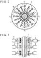
- the beating chains 11 are attached at a radially uniform interval in each stage to the shaft 7 in a staggered manner between adjacent stages. As shown in Fig. 2, specifically each beating chain 11 is attached at a position corresponding to the midway position between adjacent beating chains 11 in the next stage.
- Fig. 3 illustrates the manner in which the beating chains 11 are attached to the shaft 7.
- support bars 13 are each fitted for each beating chain 11, with a sliding gap provided, in a chain holder means 14 secured to the outer periphery of the shaft 7, and an end ring 12 of each beating chain 11 is coupled to each support bar 13.
- the steel-made cylindrical peripheral wall 4 of the crusher vessel 3 has a circular or polygonal sectional profile having a greater radius than the length, to which the bearing chains 11 revolving about the shaft 7 are stretched by the centrifugal force in the direction normal to the axial direction of the shaft 7, and prevents the object from being scattered by the centrifugal force exerted by the beating chains 11.
- a plurality of guide members 15 having a surface inclined toward the center of the crusher vessel 3 in the direction of revolving of the bearing chains 11, are provided on the inner surface of the peripheral wall 4 in portions thereof corresponding to the individual axially spaced-apart beating zones and at circumferentially spaced-apart positions.
- a rotary disc 16 is mounted on the shaft 7 for rotation about the same.
- the rotary disc 16 has a plurality of scrapers 17 provided on its top to cause the crushed object to be led downward and be pushed out of the peripheral wall 4 through the outlet 6.
- the rotary disc 16 also has a scraper 18 provided on its underside for pushing the scraped object having fallen off it toward the outlet 6.
- the chain beating type crusher according to the invention having the construction as described in the foregoing has the following beneficial effects.
- the object charged from the inlet and allowed to fall down by its own weight is beaten and crushed by the plurality of beating chains revolving at a high speed in the successive beating zones formed one below another in the direction of the fall. Since the charged object is progressively crushed by the beating action as it falls through the successive beating zones from the uppermost one, even a large mass can be finely crushed in a single crushing process. Also, finer crushing is attainable as desired by passing the object through the crusher twice, three times and so forth.
- the beating chains which provide the beating action with their high speed revolution, can change their shape when they are given strong impact by the object. That is, they can change their shape in an escaping manner when they irrationally collide with the object.
- they can crush the object without possibility of application of irrationally high load to them in their state of high speed revolution. In other words, they can crush even a hard object without possibility of their damage, and their durability can be improved.
- the plurality of guide members are provided on the inner surface of the peripheral wall of the crusher vessel in portions thereof corresponding to the beating zones, which are formed by the revolving beating chains, at circumferentially spaced-apart positions, and they each have a surface inclined toward the center of the crusher vessel in the direction of revolving of the beating chains.
- the object charged from the inlet of the chain beating type crusher is progressively crushed as it falls through the successive beating zone stages from the uppermost one.
- beating chains in each beating zone stage mounted on the shaft in staggered positions each corresponding to the midway position between adjacent beating chains in the next beating zone stage, it is possible to reduce the gap between the adjacent beating chains revolving at a high speed, through which the object passes , thus increasing the possibility that the object receives the theoretical number of times of beating actions while the object passes through each beating zone stage. Finer crushing of the object is thus possible.
- each beating chain has an end ring coupled to a corresponding one of separate support bars each fitted in a recess provided in the chain holder means secured to the outer periphery of the shaft.
Landscapes
- Engineering & Computer Science (AREA)
- Food Science & Technology (AREA)
- Crushing And Pulverization Processes (AREA)
Abstract
Description
- This invention relates to a chain beating type crusher and, more particularly, to a chain beating type crusher which belongs to the beating type crusher and which crushes an object to be processed by beating it with chains revolving at a high speed.
- As the crusher, a variety of mechanisms are available, but they require several steps for finely crushing a large mass as an object. Among the beating type crushers is, for instance, a hammer mill which crushes an object with a beating action of rotating blades. The hammer mill, however, has a problem in the durabiity of the blades because the blades are damaged when a hard object is processed.
- As a variety of the beating type crushers for crushing an object with a beating action, chain beating type crushers have recently been used, which crush an object with a beating action of chains revolving at a high speed. In such a chain beating type crusher, an object charged from above into a multistage beating zone, which has successive beating zones or stages each formed by a plurality of beating chains revolving at a high speed, is allowed to fall due to the own weight, so that it is beaten and crushed in the successive beating zones formed one below another in the falling direction. In this chain beating type crusher, the falling speed of the object and the speed of revolution of the beating chains are related such as to obtain desired crushing. Theoretically, when the time required for the object to pass through one stage of the beating zone which is formed by a plurality of beating chains revolving at a high speed is set equal to the time required for the beating chains to revolve once, the number of times of beating of the object during the passage thereof through one stage is equal to the number of the beating chains in one stage, and the object is beaten a number of times, which is the product of the number of times of beating in one beating zone stage multiplied by the number of the successive beating zone stages. Also in this chain beating type crusher, a crusher vessel thereof has a steel-made peripheral wall, which has a greater radius than the length, to which the beating chains caused to revolve at a high speed about an axis of revolution are stretched by the centrifugal force in a revolving direction perpendicular to the axis of revolution. This peripheral wall can prevent the object from being scattered by the centrifugal force to the outside of the crusher vessel.
- In the prior art chain beating type crusher, however, the considerable part of the object falls along the inner surface of the peripheral wall of the crusher vessel without receiving the theoretical number of beatings by the beating chains revolving at a high speed. That is, the number of times the object is beaten is greatly reduced.
- A first object of the invention is to provide a chain beating type crusher, which can overcome the above drawback and is adapted to give an object the theoretical number of times of beating actions by the beating chains revolving at a high speed, thus increasing the crushing efficiency.
- A second object of the invention is to provide a chain beating type crusher for crushing an object with a beating action of beating chains revolving at a high speed, which permits finer crushing of the object.
- The conventional chain beating type crusher for crushing an object with a beating action of beating chains revolving at a high speed, has a different problem. Portions of the beating chains that are mounted on the shaft are subject to severe wear caused in a long operation by the centrifugal forces of the beating chains and the high beating impact force of beating. In actual use of this chain beating type crusher, therefore, it is necessary to reduce the wear of the beating chain portions mounted on the shaft as much as possible.
- A third object of the invention is to provide a chain beating type crusher, which can solve the above problem, and in which the wear of the beating chain portions mounted on the shaft is reduced as much as possible, thus extending the service life of the beating chain portions mounted on the shaft, reducing the time of replacement and improving the durability.
- The conventional chain beating type crusher for crushing an object with a beating action of beating chains revolving at a high speed, has a further problem. A light weight object which is beaten a number of times exceeding the above theoretical number, readily becomes stagnant in the beating zone formed by the beating chains revolving at a high speed, and cannot smoothly pass continuously through the successive beating zone stages formed one below another in the direction of falling of the object. Therefore, the processing capacity is greatly reduced, resulting in excessive drive power load.
- A fourth object of the invention is to provide a beating type crusher, which can solve the above problem and allows even a light weight object to pass through the successive beating zone stages, which are formed one below another in the direction of falling of the object by the beating chains revolving at a high speed, continuously without becoming stagnant, thus increasing the crushing efficiency.
- The invention thus seeks to provide a chain beating type crusher for crushing an object with a beating action of beating chains revolving at a high speed, which has increased crushing efficiency, improved mechanical durability and excellent usefulness.
- The chain beating type crusher according to the invention comprises a crusher vessel having a steel-made peripheral wall having an inlet formed at the top for charging an object and an outlet formed adjacent the bottom for taking out the object having been crushed, a vertical shaft extending centrally of the crusher vessel and capable of being rotated about its axis, and a plurality of beating chains capable of beating and thereby crushing the object, the beating chains being mounted in a plurality of axially spaced-apart stages in each of which a plurality of radially uniformly spaced-apart chains are formed on the vertical shaft, the beating chains being capable, by causing high speed rotation of the vertical shaft, of revolving at a high speed and being stretched in directions perpendicular to the axial direction of the vertical shaft by the centrifugal force, thereby forming the axially spaced-apart beating zones individually defined by the respective beating chain stages. To attain the above first object, the chain beating type crusher according to the invention is characterized in that a plurality of guide members are provided on the inner surface of the peripheral wall of the crusher vessel in portions thereof corresponding to the beating zones and at circumferentially spaced-apart positions. These guide members each have an inclined surface inclined toward the center of the crusher vessel in the direction of revolution of the beating chains, and they serve to return the object, which has been scattered toward the inner surface of the peripheral wall by the centrifugal force of the revolving beating chains, from the inner surface toward the beating zones. With this construction of the chain beating type crusher, an object charged from the inlet is allowed to fall by its own weight to be beaten in the successive beating zones formed one below another in the direction of the fall by the beating chains revolving at a high speed, and is progressively crushed as it passes down through the successive beating zones. Besides, the beating chains which are revolving at a high speed and providing a beating action, can change their shape when they are given strong impact by the object. That is, they can change their shape in an escaping manner with respect to irrational collision with the object. It is thus possible to crush the object without irrationally high load applied to the revolving beating chains. Moreover, the guide members return the object, which has been scattered to the outside of the beating zones, i. e. , toward the inner surface of the peripheral wall of the crusher vessel, by the centrifugal force pf the beating chains revolving at a high speed, from the inner surface noted above toward the beating zones around the vertical shaft. This has an effect of permitting the object to receive the theoretical number of times of beating action by the beating chains.
- To attain the above second object, the chain beating type crusher according to the invention is characterized in that the beating chains which are arranged at a radially uniform interval, are each attached to the vertical shaft at a staggered position thereof corresponding to the midway position between adjacent ones in the next stage. With this arrangement of the chain beating type crusher, it is possible to reduce the gap between the adjacent beating chains revolving at a high speed, throuch which the object charged from the inlet passes. In other words, it is possible to increase the reliability that the process material receives the theoretical number of times of beating action while it passes through each stage beating zone.
- To attain the above third object, the chain beating type crusher according to the invention is characterized in that the beating chains each have an end ring coupled to a corresponding one of separate support bars each fitted in recesses provided in a chain holder means secured to the outer perphery of the vertical shaft. With this arrangement, in which each beating chain is coupled to each separate support bar, which is fitted in recesses provided in the chain holder means, the degree of freedom of movement of the support bar is increased to prevent partial wear thereof on one side and reduce wear of a portion of the bearing chain mounted on the vertical shaft as much as possible.
- To attain the above fourth object, the chain beating type crusher according to the invention is characterized in that it further comprises a rotary disc mounted on the vertical shaft for rotation about the axis in the lowermost portion of the crusher vessel, and a scraper means provided on the top of the rotary disc to cause the crushed object to be led downward and be pushed out of the peripheral wall through the outlet. With the provision of the scraper means to cause the crushed object to be led downward and be pushed out to the outside of the peripheral wall, even a light weight object can pass through the successive beating zones, which are formed one below another in the direction of its fall by the beating chains revolving at a high speed, continuously and without becoming accumulated in these beating zones.
-
- Fig. 1 is an elevational sectional view showing a chain beating type crusher of the invention as a whole;
- Fig. 2 is a transversal sectional view showing the manner of mounting of beating chains;
- Fig. 3 is a fragmentary enlarged-scale elevational sectioonal view showing mounting portions of the beating chains; and
- Fig. 4 is a transversal sectional view showing a rotary disc and a plurality of scrapers provided thereon.
- All embodiment of the invention will now be described with reference to the drawings. Referring to Fig. 1, a
crusher vessel 3 is secured to a base 1 vialegs 2. Thecrusher vessel 3 comprises a cylindricalperipheral wall 4 made from a steel plate and has aninlet 5 formed at the top for charging an object to be crushed and anoutlet 6 provided adjacent the bottom for taking out the crushed material. Centrally of thecrusher vessel 3, avertical shaft 7 which is rotated about its axis at a high speed is supported inbearings 8. Theshaft 7 is driven from a drive motor (not shown) via adrive belt 9, which is passed round adrive pulley 10 mounted on the lower end of theshaft 7 projecting downward from thecrusher vessel 3. Beatingchains 11 in the form of ring chains are hung in a multiplicity of axially spaced-apart stages from theshaft 7. These beating chain stages each comprise a plurality of radially uniformly spaced-apart beatingchains 11. When the crusher is not operated, thebeating chains 11 depend from theshaft 7. By causing high speed rotation of theshaft 7, the revolvingbeating chains 11 are spread by the centrifugal force into the horizontal state perpendicular to the axial direction of theshaft 7 as shown in Fig. 1. In this state, thebeating chains 11 in the individual stages define respective beating zones corresponding in thickness to the thickness of thebeating chains 11. - The beating
chains 11 are attached at a radially uniform interval in each stage to theshaft 7 in a staggered manner between adjacent stages. As shown in Fig. 2, specifically eachbeating chain 11 is attached at a position corresponding to the midway position betweenadjacent beating chains 11 in the next stage. - Fig. 3 illustrates the manner in which the
beating chains 11 are attached to theshaft 7. As shown,support bars 13 are each fitted for eachbeating chain 11, with a sliding gap provided, in a chain holder means 14 secured to the outer periphery of theshaft 7, and anend ring 12 of eachbeating chain 11 is coupled to eachsupport bar 13. - The steel-made cylindrical
peripheral wall 4 of thecrusher vessel 3 has a circular or polygonal sectional profile having a greater radius than the length, to which thebearing chains 11 revolving about theshaft 7 are stretched by the centrifugal force in the direction normal to the axial direction of theshaft 7, and prevents the object from being scattered by the centrifugal force exerted by thebeating chains 11. In order for the object, which is scattered toward the inner surface of theperipheral wall 4 by the centrifugal force of the revolvingbeating chains 11, to be returned from the above inner surface toward the beating zones defined centrally of thecrusher vessel 3 by the revolving beatingchains 11, a plurality ofguide members 15 having a surface inclined toward the center of thecrusher vessel 3 in the direction of revolving of thebearing chains 11, are provided on the inner surface of theperipheral wall 4 in portions thereof corresponding to the individual axially spaced-apart beating zones and at circumferentially spaced-apart positions. - As shown in Figs. 1 and 4, in the lowermost portion of the crusher vessel 3 a
rotary disc 16 is mounted on theshaft 7 for rotation about the same. Therotary disc 16 has a plurality ofscrapers 17 provided on its top to cause the crushed object to be led downward and be pushed out of theperipheral wall 4 through theoutlet 6. Therotary disc 16 also has ascraper 18 provided on its underside for pushing the scraped object having fallen off it toward theoutlet 6. - The chain beating type crusher according to the invention having the construction as described in the foregoing has the following beneficial effects.
- The object charged from the inlet and allowed to fall down by its own weight is beaten and crushed by the plurality of beating chains revolving at a high speed in the successive beating zones formed one below another in the direction of the fall. Since the charged object is progressively crushed by the beating action as it falls through the successive beating zones from the uppermost one, even a large mass can be finely crushed in a single crushing process. Also, finer crushing is attainable as desired by passing the object through the crusher twice, three times and so forth.
- While the object is progressively crushed as it passes through the successive beating zones, the beating chains which provide the beating action with their high speed revolution, can change their shape when they are given strong impact by the object. That is, they can change their shape in an escaping manner when they irrationally collide with the object. Thus, they can crush the object without possibility of application of irrationally high load to them in their state of high speed revolution. In other words, they can crush even a hard object without possibility of their damage, and their durability can be improved.
- The plurality of guide members are provided on the inner surface of the peripheral wall of the crusher vessel in portions thereof corresponding to the beating zones, which are formed by the revolving beating chains, at circumferentially spaced-apart positions, and they each have a surface inclined toward the center of the crusher vessel in the direction of revolving of the beating chains. Thus, when the object is scattered the inner surface of the peripheral wall of the crusher vessel, it can be returned from the peripheral wall inner surface toward the beating zones around the shaft, so that it can receive the theoretical number of times of beating actions by the beating chains. The crushing efficiency thus can be greatly increased.
- As described above, the object charged from the inlet of the chain beating type crusher is progressively crushed as it falls through the successive beating zone stages from the uppermost one. With beating chains in each beating zone stage mounted on the shaft in staggered positions each corresponding to the midway position between adjacent beating chains in the next beating zone stage, it is possible to reduce the gap between the adjacent beating chains revolving at a high speed, through which the object passes , thus increasing the possibility that the object receives the theoretical number of times of beating actions while the object passes through each beating zone stage. Finer crushing of the object is thus possible.
- As described above, each beating chain has an end ring coupled to a corresponding one of separate support bars each fitted in a recess provided in the chain holder means secured to the outer periphery of the shaft. With this arrangement, the degree of freedom of movement of the support bar is increased to prevent partial wear thereof on one side and reduce wear of a portion of the beating chain mounted on the vertical shaft as much as possible. The durability of the potion of the beating chain mounted on the shaft is thus increased, so that it is not necessary to replace the support bar frequently, thus permitting long continuous operation and increasing the processing capacity.
- Moreover, with the provision of the scraper means to cause the crushed object to be led downward and pushed to the outside of the peripheral wall, even a light weight object can pass through the successive heating zones which are formed, one below another in the direction of its fall by the beating chains revolution at a high speed, continuously and without becoming accumulated in these beating zones. A high crushing efficiency thus can be maintained even with a light weight object.
Claims (4)
- A chain beating type crusher comprising a crusher vessel (3) having a steel-made peripheral wall (4) having an inlet (5) formed at the top for charging an object and an outlet (6) formed adjacent the bottom for taking out the object having been crushed, a vertical shaft (7) extending centrally of said crusher vessel and capable of being rotated about its axis, a plurality of beating chains (11) capable of beating and thereby crushing said object, said beating chains being mounted in a plurality of axially spaced-apart stages in each of which a plurality of radially uniformly spaced-apart chains are formed on said vertical shaft (7), said beating chains being capable, by causing high speed rotation of said vertical shaft, of revolving at a high speed and being stretched in directions perpendicular to the axial direction of said vertical shaft by the centrifugal force, thereby forming axially spaced-apart beating zones individually defined by said respective beating chain stages, and a plurality of guide members (15) provided on the inner surface of said peripheral wall (4) of said crusher vessel in portions thereof corresponding to said beating zones and at circumferentially spaced-apart positions, said guide members each having a surface inclined toward the center of said crusher vessel in the direction of revolution of said beating chains for said object having been scattered toward said inner surface of said peripheral wall by the centrifugal force exerted by said revolving bearing chains to be returned from said inner surface toward said beating zones.
- The chain beating type crusher according to claim 1, wherein said beating chains (11) in the radially uniform interval arrangement are each attached to said vertical shaft at a staggered position thereof corresponding to the midway position between adjacent beating chains in the next stage.
- The chain beating type crusher according to claim 1, wherein said beating chains each have an end ring (12) coupled to a corresponding one of support bars (13) each fitted in a recess provided in a chain holder means (14) secured to the outer periphery of said vertical shaft.
- The chain beating type crusher according to claim 1, which further comprises a rotary disc (16) mounted on said vertical shaft for rotation about the axis in the lowermost portion of said crusher vessel, and a scraper means (17) provided on the top of said rotary disc to cause the crushed object to be led downward and pushed out of said peripheral wall through said outlet.
Applications Claiming Priority (1)
| Application Number | Priority Date | Filing Date | Title |
|---|---|---|---|
| PCT/JP1994/001382 WO1996005912A1 (en) | 1994-08-22 | 1994-08-22 | Chain beating type crusher |
Publications (3)
| Publication Number | Publication Date |
|---|---|
| EP0778086A1 true EP0778086A1 (en) | 1997-06-11 |
| EP0778086A4 EP0778086A4 (en) | 2000-06-28 |
| EP0778086B1 EP0778086B1 (en) | 2002-11-06 |
Family
ID=14098596
Family Applications (1)
| Application Number | Title | Priority Date | Filing Date |
|---|---|---|---|
| EP94924400A Expired - Lifetime EP0778086B1 (en) | 1994-08-22 | 1994-08-22 | Chain beating type crusher |
Country Status (6)
| Country | Link |
|---|---|
| US (1) | US5697563A (en) |
| EP (1) | EP0778086B1 (en) |
| KR (1) | KR100328915B1 (en) |
| CA (1) | CA2197453C (en) |
| DE (1) | DE69431673T2 (en) |
| WO (1) | WO1996005912A1 (en) |
Cited By (3)
| Publication number | Priority date | Publication date | Assignee | Title |
|---|---|---|---|---|
| WO2004024331A1 (en) * | 2002-08-29 | 2004-03-25 | Bhs-Sonthofen Gmbh | Comminuting device |
| WO2009027062A1 (en) * | 2007-08-25 | 2009-03-05 | Weingart Und Kubrat Gmbh | Process and plant for obtaining metal parts from residues of waste incineration processes |
| FR2951660A1 (en) * | 2009-10-23 | 2011-04-29 | Phenix Ind | Aggregate processing device, has resonance vibrating sieve with sieving surfaces, where sieve is equipped with inlet for battered aggregate, outlet for sieved metallic component, and another outlet for sieved non-residual aggregate |
Families Citing this family (28)
| Publication number | Priority date | Publication date | Assignee | Title |
|---|---|---|---|---|
| US6039277A (en) * | 1998-11-06 | 2000-03-21 | Hamm; Robert L. | Pulverizer |
| DE19903525A1 (en) * | 1999-01-29 | 2000-08-03 | Mewa Recycling Maschinen Und A | Disassembly device for old devices |
| DE10322624B4 (en) * | 2003-05-20 | 2008-05-08 | Mewa Recycling Maschinen Und Anlagenbau Gmbh | digestion facility |
| US20070205605A1 (en) * | 2006-03-02 | 2007-09-06 | I-Tek Metal Mfg. Co., Ltd. | Bolt assembly for lock |
| EP1886729B1 (en) * | 2006-08-02 | 2009-03-11 | Anlagenbau Umwelt + Technik Chemnitz GmbH | Comminution device and comminuting method |
| US7862599B2 (en) * | 2007-01-23 | 2011-01-04 | Arizant Healthcare Inc. | Convective warming device with a drape |
| KR100774488B1 (en) * | 2007-05-03 | 2007-11-08 | 대길산업주식회사 | Vertical Swing Hammer Crusher with Beet Hammer, Detachable Arc Shape |
| ITMI20110320A1 (en) * | 2011-03-01 | 2012-09-02 | Chrysopoeia Srl | WASTE MILL |
| DE102011120630A1 (en) | 2011-12-09 | 2013-06-13 | Aerocycle Gmbh | Process for recycling waste paper |
| DE202012100485U1 (en) * | 2012-02-14 | 2013-05-16 | Recuperma Gmbh | Drive a crusher |
| DE102012104031B4 (en) * | 2012-05-08 | 2017-05-04 | Pms Handelskontor Gmbh | Separating device for material conglomerates |
| US9751087B2 (en) * | 2012-09-20 | 2017-09-05 | Gary L. Watts | Comminution mill with cable impact arms |
| US9498780B2 (en) | 2012-09-20 | 2016-11-22 | Gary L. Watts | Grinding mill with cable grinding arms |
| EP2837424A1 (en) * | 2013-08-13 | 2015-02-18 | TARTECH eco industries AG | Slag crusher |
| DE102013110352A1 (en) * | 2013-09-19 | 2015-03-19 | Pms Handelskontor Gmbh | comminution device |
| US9481105B2 (en) | 2013-12-12 | 2016-11-01 | Watershed Materials, Llc | System, method and apparatus for fabricating environmental masonry units |
| US10486345B2 (en) | 2015-02-27 | 2019-11-26 | Watershed Materials, Llc | Dynamic block press, and associated methods and systems |
| US10569238B2 (en) | 2015-02-27 | 2020-02-25 | Watershed Materials, Llc | Vertical shaft high-shear mixer for de-agglomeration, and associated methods and systems |
| US11744404B2 (en) * | 2018-01-26 | 2023-09-05 | G&E Innovations, Inc. | Grinder |
| CN109718932B (en) * | 2019-01-28 | 2020-11-27 | 宿迁市创盈知识产权服务有限公司 | Domestic garbage reprocessing technology |
| CN109718905B (en) * | 2019-01-28 | 2021-03-30 | 重庆外宇科技有限公司 | High-efficient sorting device of domestic waste |
| KR102034413B1 (en) * | 2019-07-04 | 2019-11-18 | 주식회사 아진피앤피 | Pulverizing device for papermaking |
| IT201900011376A1 (en) * | 2019-07-10 | 2021-01-10 | Itea Spa | Process and device for grinding heterogeneous matrices |
| CN110841770A (en) * | 2019-10-12 | 2020-02-28 | 广西力源宝科技有限公司 | Vertical chain crusher convenient to clean and cleaning method |
| JP2021065863A (en) * | 2019-10-28 | 2021-04-30 | 株式会社五十鈴製作所 | Core crushing device |
| US11516970B2 (en) * | 2019-10-30 | 2022-12-06 | Raymond Boone | Agricultural shredder |
| EP4101541A4 (en) * | 2020-02-07 | 2024-05-22 | JDC Corporation | ROTARY GRINDING DEVICE AND METHOD |
| CN117259734B (en) * | 2023-11-22 | 2024-03-15 | 江苏祥荣机械制造有限公司 | Sand casting shakeout equipment for shaft sleeve sand mould |
Family Cites Families (17)
| Publication number | Priority date | Publication date | Assignee | Title |
|---|---|---|---|---|
| US1728976A (en) * | 1927-10-03 | 1929-09-24 | Harry M Nobis | Apparatus for pulverizing coal |
| US2525023A (en) * | 1948-06-01 | 1950-10-10 | Ralph B Ensminger | Portable soil mill with adjustable legs |
| US2592481A (en) * | 1948-06-18 | 1952-04-08 | Arthur M Spencer | Fiber beater for the liberation of cellulose fibers |
| US2965320A (en) * | 1957-01-28 | 1960-12-20 | Naturizer Co | Material reducing apparatus |
| GB890681A (en) * | 1960-09-14 | 1962-03-07 | Naturizer Co | Material reducing apparatus |
| US3973735A (en) * | 1974-04-01 | 1976-08-10 | Keishin Matsumoto, President of Agency of Industrial Science and Technology | Apparatus for pulverizing and sorting municipal waste |
| US3993256A (en) * | 1975-08-28 | 1976-11-23 | Garbalizer Corporation Of America | Waste mangler system and structure |
| DE2748312A1 (en) * | 1976-11-01 | 1978-05-03 | Michel Albert Jadouin | SHREDDER |
| US4119453A (en) * | 1976-11-26 | 1978-10-10 | Mike Knezevich | Process for reclaiming and upgrading thin-walled malleable waste material |
| JPS56238A (en) * | 1979-06-11 | 1981-01-06 | Sumitomo Metal Mining Co Ltd | Method of recovering copper and zinc from copper slag at vertical blast furnace |
| JPS56238U (en) * | 1979-06-15 | 1981-01-06 | ||
| JPS588899B2 (en) * | 1979-10-12 | 1983-02-18 | 三晃技研株式会社 | Sorting machine |
| DE3125276C2 (en) * | 1981-06-25 | 1983-06-16 | Mannesmann AG, 4000 Düsseldorf | Metal hydride storage |
| JPS592841Y2 (en) * | 1981-09-02 | 1984-01-26 | 日本国有鉄道 | Train garbage sorting device |
| US4442167A (en) * | 1982-06-30 | 1984-04-10 | Toyoda Gosei Kabushiki Kaisha | Weather resisting extruded rubbery articles having on the surface thereof a thin layer of a colored rubbery material |
| US4875630A (en) * | 1988-10-11 | 1989-10-24 | Carlson William P | Leaf vacuum and shredder |
| US5630556A (en) * | 1995-11-07 | 1997-05-20 | Chrestenson; Robert A. | Portable apparatus for comminuting gypsum wallboard |
-
1994
- 1994-08-22 US US08/793,120 patent/US5697563A/en not_active Expired - Fee Related
- 1994-08-22 CA CA002197453A patent/CA2197453C/en not_active Expired - Fee Related
- 1994-08-22 EP EP94924400A patent/EP0778086B1/en not_active Expired - Lifetime
- 1994-08-22 DE DE69431673T patent/DE69431673T2/en not_active Expired - Fee Related
- 1994-08-22 KR KR1019970701122A patent/KR100328915B1/en not_active Expired - Fee Related
- 1994-08-22 WO PCT/JP1994/001382 patent/WO1996005912A1/en not_active Ceased
Cited By (5)
| Publication number | Priority date | Publication date | Assignee | Title |
|---|---|---|---|---|
| WO2004024331A1 (en) * | 2002-08-29 | 2004-03-25 | Bhs-Sonthofen Gmbh | Comminuting device |
| CN100374208C (en) * | 2002-08-29 | 2008-03-12 | Bhs桑托芬有限公司 | Crushing device |
| US7533837B2 (en) | 2002-08-29 | 2009-05-19 | Bhs-Sonthofen, Gmbh | Comminuting device |
| WO2009027062A1 (en) * | 2007-08-25 | 2009-03-05 | Weingart Und Kubrat Gmbh | Process and plant for obtaining metal parts from residues of waste incineration processes |
| FR2951660A1 (en) * | 2009-10-23 | 2011-04-29 | Phenix Ind | Aggregate processing device, has resonance vibrating sieve with sieving surfaces, where sieve is equipped with inlet for battered aggregate, outlet for sieved metallic component, and another outlet for sieved non-residual aggregate |
Also Published As
| Publication number | Publication date |
|---|---|
| DE69431673D1 (en) | 2002-12-12 |
| US5697563A (en) | 1997-12-16 |
| KR970705439A (en) | 1997-10-09 |
| KR100328915B1 (en) | 2002-11-22 |
| EP0778086B1 (en) | 2002-11-06 |
| DE69431673T2 (en) | 2003-07-10 |
| EP0778086A4 (en) | 2000-06-28 |
| CA2197453A1 (en) | 1996-02-29 |
| WO1996005912A1 (en) | 1996-02-29 |
| CA2197453C (en) | 2001-10-30 |
Similar Documents
| Publication | Publication Date | Title |
|---|---|---|
| US5697563A (en) | Chain beating type crusher | |
| RU2353431C1 (en) | Desintegrator | |
| US3211387A (en) | Grinding mill lining and control of the wear thereof | |
| RU2412764C1 (en) | Disintegrator | |
| US8231007B2 (en) | Static classifier cage | |
| TWI840431B (en) | Supported toothed plates in a disperser | |
| US11192116B2 (en) | Vertical shaft impact crusher | |
| CN1127677A (en) | Horizontal Conical Rotor Impact Crusher | |
| CN119772759A (en) | Improvement of agitated bead mill | |
| JP3144728B2 (en) | Chain impact crusher | |
| US4936513A (en) | Ball mills | |
| RU102540U1 (en) | VERTICAL HAMMER MILL | |
| SU1357066A1 (en) | Apparatus for grinding materials | |
| US3671019A (en) | Apparatus for material fluffing | |
| RU226429U1 (en) | Rotary Disc Shredder | |
| US6902A (en) | Improvement in machinery-for dressing flour | |
| CN1159164A (en) | Chain beating type crusher | |
| SU1738335A1 (en) | Disintegrator | |
| RU2016653C1 (en) | Hot sinter toothed-single-roll crusher | |
| RU2794358C1 (en) | Lining plate kit | |
| RU2000142C1 (en) | Centrifugal multistage crusher | |
| CN1315585C (en) | Drum-type grading machine for corn and other grain granule | |
| RU240641U1 (en) | Mill | |
| RU205450U1 (en) | Dynamic autogenous grinding mill | |
| RU2742509C1 (en) | Hammer grain grinder with vertical rotor |
Legal Events
| Date | Code | Title | Description |
|---|---|---|---|
| PUAI | Public reference made under article 153(3) epc to a published international application that has entered the european phase |
Free format text: ORIGINAL CODE: 0009012 |
|
| 17P | Request for examination filed |
Effective date: 19970320 |
|
| AK | Designated contracting states |
Kind code of ref document: A1 Designated state(s): DE FR GB SE |
|
| RIC1 | Information provided on ipc code assigned before grant |
Free format text: 7B 02C 13/16 A, 7B 02C 13/282 B |
|
| A4 | Supplementary search report drawn up and despatched |
Effective date: 20000515 |
|
| AK | Designated contracting states |
Kind code of ref document: A4 Designated state(s): DE FR GB SE |
|
| 17Q | First examination report despatched |
Effective date: 20001024 |
|
| GRAG | Despatch of communication of intention to grant |
Free format text: ORIGINAL CODE: EPIDOS AGRA |
|
| GRAG | Despatch of communication of intention to grant |
Free format text: ORIGINAL CODE: EPIDOS AGRA |
|
| GRAH | Despatch of communication of intention to grant a patent |
Free format text: ORIGINAL CODE: EPIDOS IGRA |
|
| GRAH | Despatch of communication of intention to grant a patent |
Free format text: ORIGINAL CODE: EPIDOS IGRA |
|
| GRAA | (expected) grant |
Free format text: ORIGINAL CODE: 0009210 |
|
| AK | Designated contracting states |
Kind code of ref document: B1 Designated state(s): DE FR GB SE |
|
| PG25 | Lapsed in a contracting state [announced via postgrant information from national office to epo] |
Ref country code: FR Free format text: LAPSE BECAUSE OF FAILURE TO SUBMIT A TRANSLATION OF THE DESCRIPTION OR TO PAY THE FEE WITHIN THE PRESCRIBED TIME-LIMIT Effective date: 20021106 |
|
| REG | Reference to a national code |
Ref country code: GB Ref legal event code: FG4D |
|
| REF | Corresponds to: |
Ref document number: 69431673 Country of ref document: DE Date of ref document: 20021212 |
|
| PG25 | Lapsed in a contracting state [announced via postgrant information from national office to epo] |
Ref country code: SE Free format text: LAPSE BECAUSE OF FAILURE TO SUBMIT A TRANSLATION OF THE DESCRIPTION OR TO PAY THE FEE WITHIN THE PRESCRIBED TIME-LIMIT Effective date: 20030206 |
|
| EN | Fr: translation not filed | ||
| PLBE | No opposition filed within time limit |
Free format text: ORIGINAL CODE: 0009261 |
|
| STAA | Information on the status of an ep patent application or granted ep patent |
Free format text: STATUS: NO OPPOSITION FILED WITHIN TIME LIMIT |
|
| 26N | No opposition filed |
Effective date: 20030807 |
|
| PGFP | Annual fee paid to national office [announced via postgrant information from national office to epo] |
Ref country code: GB Payment date: 20040812 Year of fee payment: 11 |
|
| PGFP | Annual fee paid to national office [announced via postgrant information from national office to epo] |
Ref country code: DE Payment date: 20041028 Year of fee payment: 11 |
|
| PG25 | Lapsed in a contracting state [announced via postgrant information from national office to epo] |
Ref country code: GB Free format text: LAPSE BECAUSE OF NON-PAYMENT OF DUE FEES Effective date: 20050822 |
|
| PG25 | Lapsed in a contracting state [announced via postgrant information from national office to epo] |
Ref country code: DE Free format text: LAPSE BECAUSE OF NON-PAYMENT OF DUE FEES Effective date: 20060301 |
|
| GBPC | Gb: european patent ceased through non-payment of renewal fee |
Effective date: 20050822 |