EP0778171B1 - Windschott für ein Cabriolet - Google Patents
Windschott für ein Cabriolet Download PDFInfo
- Publication number
- EP0778171B1 EP0778171B1 EP96115436A EP96115436A EP0778171B1 EP 0778171 B1 EP0778171 B1 EP 0778171B1 EP 96115436 A EP96115436 A EP 96115436A EP 96115436 A EP96115436 A EP 96115436A EP 0778171 B1 EP0778171 B1 EP 0778171B1
- Authority
- EP
- European Patent Office
- Prior art keywords
- vehicle
- wind break
- seats
- plate
- portions
- Prior art date
- Legal status (The legal status is an assumption and is not a legal conclusion. Google has not performed a legal analysis and makes no representation as to the accuracy of the status listed.)
- Expired - Lifetime
Links
Images


Classifications
-
- B—PERFORMING OPERATIONS; TRANSPORTING
- B60—VEHICLES IN GENERAL
- B60J—WINDOWS, WINDSCREENS, NON-FIXED ROOFS, DOORS, OR SIMILAR DEVICES FOR VEHICLES; REMOVABLE EXTERNAL PROTECTIVE COVERINGS SPECIALLY ADAPTED FOR VEHICLES
- B60J7/00—Non-fixed roofs; Roofs with movable panels, e.g. rotary sunroofs
- B60J7/22—Wind deflectors for open roofs
- B60J7/223—Wind deflectors for open roofs specially adapted for convertible cars
Definitions
- the invention relates to a wind deflector for a convertible according to the preamble of Claim 1.
- a wind deflector for a convertible that is arranged behind a row of seats and in its operative position a first, extending beyond the seats, across the entire width of the interior extending upright part includes, with its lower edge approximately at the level of Belt line ends and there over hinges to an approximately horizontal one opening behind second part covering the seats is connected.
- the first part can be folded down to the second part when not in use Detach from the body in the folded position in the vehicle. On such folded wind deflector, however, requires a relatively large amount of storage space in the Vehicle.
- the object of the invention is a wind deflector of the type mentioned above to further develop that it is easy and space-saving in the vehicle when not in use can be accommodated.
- the main advantages achieved with the invention are the fact that the wind deflector according to the invention can be folded up in a particularly space-saving manner. This will thereby achieved that on the one hand the second part is formed in two parts, the in In the operative position, parts lying next to one another are releasably attached to one another are. On the other hand, the upright part can be locked in place by means of latches provided put two halves together.
- At least one hinge is provided.
- the two adjacent plate sections can be detached from one another connected.
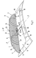
- Fig. 1 of the drawing is behind the seats 1 of the Cabriolets 2 shown a wind deflector 3 arranged, which consists of a first upright part 4 and a second, approximately horizontal part 5, wherein the part 5, which covers the rear space behind the seats 1 upwards.
- the first Upright part 4 is formed by a flexible network 7 spanned in a frame 6 formed, whereas the second part 5 is designed as a plate-shaped cover 8.
- the first upright part 4 is pivotable about 9 with the hinges plate-shaped cover 8 connected.
- This is shown in the exemplary embodiment a laminated hardboard (Fig. 9) is formed.
- the plate-shaped cover 8 is also the possibility to form the plate-shaped cover 8 as a plastic part, which on its Has a grain on the outside or is provided with an additional cover.
- the plate-shaped cover 8 covers luggage that is on the underlying rear seat system are not shown, so that this are not visible from above.
- the plate-shaped cover 8 is approximately at the level of Belt line arranged and adapted to the circumferential contour of the rear room.
- the plate-shaped cover 8 prevents the entry of air in the underlying Area of the rear room.
- the plate-shaped cover 8 At the rear transverse edge of the plate-shaped cover 8 are two protruding plug-in tabs 10 extending in the longitudinal direction of the vehicle arranged, the adjacent belt outlet openings, not shown can be inserted and held in position.
- a first hinge part 11 is located in the area of the laterally outer hinges 9 led down and there has a receptacle 12 for one in Vehicle transverse direction extending spring-loaded bolt 13, which at assembled wind deflector 3 engages in a body-side receiving member 14 (Fig. 4).
- the spring-loaded bolt 13 is in by means of a pin-shaped grip section 28 Transverse direction and radial direction shiftable (Fig. 4 and 5).
- the above Handle section 28 is fixedly connected to the bolt 13.
- One piece with the U-shaped holding section 15 formed upright hinge part 11 approximately horizontal or slightly oblique and takes the between webs 16, 17 front end of the cover 8, the cover 8 being fixed to the webs 16, 17 is connected.
- the wind deflector 3 according to the invention can be particularly space-saving fold up so that there is little installation space in the vehicle in this state claimed.
- the plate-shaped cover 8 in two parts is trained.
- the two plate sections 18, 19 are in the vehicle transverse direction seen arranged side by side, the common Connection area 20 in the exemplary embodiment approximately in the area of a Vehicle longitudinal median plane A-A is.
- both plate sections 18, 19 can be detached connected with each other. This can be done by a zipper, a tongue and groove connection or there is a partial overlap (Fig. 3).
- the first upright part 4 is opened to the rear the second part 5 folded down. Then both superimposed parts 4, 5 due to the locking joints 23 of the frame 6 and the releasable connection of the two Fold the plate sections 18, 19 together again.
- the two locking joints 23 are connected to one another via an axis 27 around which the superimposed ones Parts 4, 5 of the wind deflector 3 are collapsible again.
- the folding package 26 shown in FIG. 7 is composed of the inner halves 24, 25 of the first part 4 and the outer plate sections 18, 19 of the second Part 5 together. Means for defining the folding package 26 in the folded position may be provided.
- Fig. 8 shows the locking joint 23 between the halves 24, 25 of the first part 4, wherein by a spring-loaded ball 29 and two notches 30, 31 the positions of the halves 24, 25 are defined in the active position and the folded position.
- FIG. 9 shows the structure of the plate-shaped cover 8.
- the top the hardboard 32 is provided with a padding 33.
- the outside of Padding 33 and hardboard 32 are each characterized by a cover 34 Artificial leather or soft top covered.
Landscapes
- Engineering & Computer Science (AREA)
- Mechanical Engineering (AREA)
- Body Structure For Vehicles (AREA)
- Vehicle Step Arrangements And Article Storage (AREA)
Description
- Fig. 1
- eine perspektivische Teilansicht von schräg vorne auf ein Cabriolet mit einem ninter den Sitzen angeordneten Windschott in Wirkstellung,
- Fig. 2
- eine perspektivische Teilansicht von schräg hinten auf das Windschott und den angrenzenden Aufbau,
- Fig. 3
- einen Schnitt nach der Linie III-III der Fig. 2 in größerem Maßstab,
- Fig. 4
- eine Teilansicht von hinten, teilweise im Schnitt auf die aufbauseitige Lagerung des Windschotts,
- Fig. 5
- einen Schnitt nach der Linie V-V der Fig. 4,
- Fig. 6
- einen Schnitt nach der Linie VI-VI der Fig. 4,
- Fig. 7
- eine Ansicht von oben auf das zusammengefaltete Windschott,
- Fig. 8
- einen Schnitt nach der Linie VIII-VIII der Fig. 2 durch das Rastgelenk und
- Fig. 9
- einen Schnitt nach der Linie IX-IX der Fig. 1 in größerem Maßstab.
Claims (5)
- Windschott (3) für ein Cabriolet (2), das hinter einer Sitzreihe angeordnet ist und in seiner Wirkstellung ein erstes, über die Sitze hinaus nach oben erstreckendes, über die gesamte Innenraumbreite verlaufendes aufrechtes Teil umfaßt, das mit seiner Unterkante etwa in Höhe der Gürtellinie endet und dort über Scharniere an ein etwa horizontales, eine Öffnung hinter den Sitzen (1) nach oben abdeckendes zweites Teil (5) angeschlossen ist, wobei das erste Teil (4) nach hinten auf das zweite (5) abklappbar ist, dadurch gekennzeichnet, daß im Bereich einer Fahrzeuglängsmittelebene (A-A) an einem oberen und einem unteren querverlaufenden Rahmenabschnitt (21, 22) des ersten Teils (4) jeweils ein Rastgelenk (23) angeordnet ist, das den Rahmen (6) des ersten Teils (4) in zwei nebeneinanderliegende Hälften (24, 25) teilt und daß das zweite Teil (5) durch zwei in Fahrzeugquerrichtung gesehen nebeneinanderliegende Abschnitte gebildet wird, deren gemeinsamer Verbindungsbereich (20) etwa im Bereich der Fahrzeuglängsmittelebene (A-A) liegt, so daß nach Abklappen des ersten Teils (4) auf das zweite Teil (5) die beiden übereinanderliegenden Teile (4, 5) nochmals um eine die beiden Rastgelenke (23) miteinander verbindende Achse (27) zusammenklappbar sind.
- Windschott nach Anspruch 1, dadurch gekennzeichnet, daß die beiden Abschnitte des zweiten Teils (5) durch Plattenabschnitte (18, 19) gebildet werden, wobei in Fahrzeugquerrichtung gesehen nebeneinanderliegende Plattenabschnitte (18, 19) jeweils über zumindest ein Scharnier (9) mit einem unteren Rahmenabschnitt (21) des ersten Teils (4) gelenkig verbunden sind.
- Windschott nach Anspruch 2, dadurch gekennzeichnet, daß die beiden Plattenabschnitte (18, 19) in der Wirkstellung (B) des Windschotts (3) im Bereich einer Fahrzeuglängsmittelebene (A-A) lösbar miteinander verbunden sind.
- Windschott nach Anspruch 2, dadurch gekennzeichnet, daß jeder Plattenabschnitt (18, 19) durch eine kaschierte Hartfaserplatte (32) oder ein Kunststoffteil gebildet wird.
- Windschott nach Anspruch 2, dadurch gekennzeichnet, daß die beiden Plattenabschnitte (18, 19) in der Wirkstellung (B) des Windschotts (3) über einen Reißverschluß, eine Nut-Federverbindung, eine bereichsweise Überlappung oder dergleichen aneinander angeschlossen sind.
Applications Claiming Priority (2)
| Application Number | Priority Date | Filing Date | Title |
|---|---|---|---|
| DE19545405 | 1995-12-06 | ||
| DE19545405A DE19545405A1 (de) | 1995-12-06 | 1995-12-06 | Windschott für ein Cabriolet |
Publications (2)
| Publication Number | Publication Date |
|---|---|
| EP0778171A1 EP0778171A1 (de) | 1997-06-11 |
| EP0778171B1 true EP0778171B1 (de) | 2000-05-24 |
Family
ID=7779273
Family Applications (1)
| Application Number | Title | Priority Date | Filing Date |
|---|---|---|---|
| EP96115436A Expired - Lifetime EP0778171B1 (de) | 1995-12-06 | 1996-09-26 | Windschott für ein Cabriolet |
Country Status (4)
| Country | Link |
|---|---|
| US (1) | US5738404A (de) |
| EP (1) | EP0778171B1 (de) |
| JP (1) | JP3892512B2 (de) |
| DE (2) | DE19545405A1 (de) |
Families Citing this family (39)
| Publication number | Priority date | Publication date | Assignee | Title |
|---|---|---|---|---|
| DE19700739C1 (de) * | 1997-01-11 | 1998-03-05 | Daimler Benz Ag | Windschottanordnung für ein offenes Kraftfahrzeug |
| JP3849219B2 (ja) * | 1997-03-31 | 2006-11-22 | マツダ株式会社 | オープンカーの風の巻き込み防止装置 |
| DE29822230U1 (de) * | 1998-12-14 | 1999-02-25 | Stobinski, Peter, 71032 Böblingen | Zusammenlegbarer Windschutz für Cabrio-Personenkraftwagen |
| DE19902205B4 (de) * | 1999-01-21 | 2006-01-12 | Audi Ag | Verwendung eines Bauteils als Hutablage eines Fahrzeugs |
| DE19908499C1 (de) * | 1999-02-26 | 2000-04-20 | Daimler Chrysler Ag | Windschottanordnung |
| DE19908497C2 (de) * | 1999-02-26 | 2003-03-13 | Daimler Chrysler Ag | Offenes Kraftfahrzeug |
| DE19908502C1 (de) * | 1999-02-26 | 2000-05-04 | Daimler Chrysler Ag | Offenes Kraftfahrzeug |
| US6341812B1 (en) | 1999-07-28 | 2002-01-29 | Wayne Knoll | Wind deflecting device for vehicles |
| US6926062B2 (en) | 2000-03-13 | 2005-08-09 | Oris Fahrzeugteile Hans Riehle Gmbh | Screen element for motor vehicles; in particular, wind blocker |
| DE10012167A1 (de) * | 2000-03-13 | 2001-09-27 | Oris Fahrzeugteile Riehle H | Abschirmelement für Kraftfahrzeuge |
| DE10053701A1 (de) * | 2000-10-24 | 2002-05-08 | Oris Fahrzeugteile Riehle H | Windstopeinrichtung |
| DE10061562A1 (de) | 2000-12-04 | 2002-06-13 | Oris Fahrzeugteile Riehle H | Windschott |
| DE10063770B4 (de) * | 2000-12-21 | 2007-08-02 | Daimlerchrysler Ag | Windschutzvorrichtung für ein Kraftfahrzeug |
| DE10102662B4 (de) * | 2001-01-17 | 2004-11-11 | Oris Fahrzeugteile Hans Riehle Gmbh | Windschotteinrichtung |
| DE10219610B4 (de) | 2002-05-02 | 2018-10-11 | Audi Ag | Sonnenschutzvorrichtung |
| DE10336483A1 (de) * | 2003-08-08 | 2005-03-03 | Hartl, Günther | Windschutzvorrichtung für ein offenes Kraftfahrzeug |
| EP1718486B1 (de) * | 2004-02-17 | 2013-06-26 | Wilhelm Karmann GmbH | Windschutzscheibenabweiser für kraftfahrzeuge |
| DE102004032380A1 (de) * | 2004-06-29 | 2006-01-19 | Oris Fahrzeugteile Hans Riehle Gmbh | Windstopeinrichtung |
| DE102004032379A1 (de) | 2004-06-29 | 2006-01-19 | Oris Fahrzeugteile Hans Riehle Gmbh | Windstopeinrichtung |
| US7226118B2 (en) | 2004-06-29 | 2007-06-05 | Scambia Industrial Developments Aktiengesellschaft | Wind stop device |
| DE102004037482A1 (de) * | 2004-07-27 | 2006-02-16 | Oris Fahrzeugteile Hans Riehle Gmbh | Windstopeinrichtung |
| DE102004038070A1 (de) | 2004-07-28 | 2006-02-16 | Oris Fahrzeugteile Hans Riehle Gmbh | Element für Kraftfahrzeuge und Verfahren zur Herstellung desselben |
| DE102004061758B4 (de) * | 2004-12-22 | 2015-08-13 | Volkswagen Ag | Windstopeinrichtung |
| DE102005056242B4 (de) * | 2005-11-25 | 2019-06-27 | Volkswagen Ag | Windstoppeinrichtung |
| DE102005056243A1 (de) * | 2005-11-25 | 2007-06-06 | Volkswagen Ag | Windstoppeinrichtung |
| DE102006025501B4 (de) * | 2006-05-30 | 2017-10-05 | Fkt Gmbh | Windschotteinrichtung für ein Personenkraftfahrzeug |
| DE102006029133B4 (de) * | 2006-06-22 | 2015-09-03 | Fkt Gmbh | Schott für ein Personenkraftfahrzeug |
| US20080001428A1 (en) * | 2006-06-28 | 2008-01-03 | Hans Pehrson | Foldable wind breaker |
| DE102006030076A1 (de) * | 2006-06-28 | 2008-01-03 | iKON GbR Körber & Ortel (vertretungsberechtigte Gesellschafter Stefan Körber, 85092 Kösching und Andreas Ortel, 92334 Berching) | Schott für einen PKW |
| DE102006043626A1 (de) * | 2006-09-12 | 2008-03-27 | Scambia Industrial Developments Aktiengesellschaft | Windstopeinrichtung |
| DE102006059918B4 (de) * | 2006-12-19 | 2017-02-09 | Volkswagen Ag | Windstopeinrichtung mit motorischem Antrieb |
| DE102007016152B4 (de) * | 2007-04-02 | 2013-12-19 | Fkt Gmbh | Windschott für einen PKW |
| US20090021051A1 (en) * | 2007-07-20 | 2009-01-22 | Brown Steve H | Window assembly for a utility terrain vehicle |
| DE102008000007A1 (de) * | 2008-01-04 | 2009-07-09 | iKON GbR Körber & Ortel (vertretungsberechtigte Gesellschafter: Stefan Körber | Personenkraftfahrzeug sowie Windschotteinrichtung |
| JP5002472B2 (ja) * | 2008-01-31 | 2012-08-15 | 株式会社パイオラックス | 走行風巻込み防止装置用保持部材 |
| DE102008033520A1 (de) | 2008-07-11 | 2010-01-14 | Scambia Industrial Developments Aktiengesellschaft | Wind-, Sicht- oder Lichtschutzelement |
| DE102009035335A1 (de) * | 2009-07-21 | 2011-01-27 | Scambia Industrial Developments Aktiengesellschaft | Antriebseinheit für eine Windstopeinrichtung |
| DE102012100585B4 (de) | 2012-01-24 | 2022-03-17 | Fkt Gmbh | Windschott mit einem Gelenk |
| US20140077520A1 (en) * | 2012-03-22 | 2014-03-20 | Marcia A. Mcmanus | Sun screen |
Family Cites Families (9)
| Publication number | Priority date | Publication date | Assignee | Title |
|---|---|---|---|---|
| DE3537644C1 (de) * | 1985-10-23 | 1987-04-16 | Ford Werke Ag | Abdeckung fuer den Fahrgastraum eines Kabrioletts |
| DE3844844C3 (de) * | 1987-11-13 | 1998-07-23 | Daimler Benz Ag | Windschutz für Cabriolets |
| DE3923558A1 (de) * | 1988-09-28 | 1990-03-29 | Fuellgraf Karl Heinz | Windabweisende teilabdeckung fuer cabriolets |
| US4890876A (en) * | 1989-01-04 | 1990-01-02 | Gaines Van G | Portable roadster cover |
| DE3914035C1 (de) * | 1989-04-28 | 1990-04-26 | Daimler-Benz Aktiengesellschaft, 7000 Stuttgart, De | |
| US5318337A (en) * | 1989-04-28 | 1994-06-07 | Mercedes-Benz Ag | Windscreen arrangement for a convertible |
| DE4037705C1 (de) * | 1990-11-27 | 1991-10-24 | Mercedes-Benz Aktiengesellschaft, 7000 Stuttgart, De | |
| DE4335103C1 (de) * | 1993-10-14 | 1994-11-10 | Bayerische Motoren Werke Ag | Windschutz für Fahrzeuge, insbesondere an einem Cabriolet, Roadster oder dergleichen |
| DE4338102C2 (de) * | 1993-11-08 | 1996-05-09 | Daimler Benz Ag | Windschott für einen offenen Personenkraftwagen |
-
1995
- 1995-12-06 DE DE19545405A patent/DE19545405A1/de not_active Withdrawn
-
1996
- 1996-09-26 DE DE59605297T patent/DE59605297D1/de not_active Expired - Lifetime
- 1996-09-26 EP EP96115436A patent/EP0778171B1/de not_active Expired - Lifetime
- 1996-12-04 JP JP32413396A patent/JP3892512B2/ja not_active Expired - Fee Related
- 1996-12-06 US US08/761,786 patent/US5738404A/en not_active Expired - Lifetime
Also Published As
| Publication number | Publication date |
|---|---|
| DE59605297D1 (de) | 2000-06-29 |
| EP0778171A1 (de) | 1997-06-11 |
| JP3892512B2 (ja) | 2007-03-14 |
| US5738404A (en) | 1998-04-14 |
| JPH09175192A (ja) | 1997-07-08 |
| DE19545405A1 (de) | 1997-06-12 |
Similar Documents
| Publication | Publication Date | Title |
|---|---|---|
| EP0778171B1 (de) | Windschott für ein Cabriolet | |
| DE3816834C2 (de) | ||
| EP0521307B2 (de) | Faltverdeck für einen Personenkraftwagen mit aufklappbarem Dach | |
| EP0835778B1 (de) | Kraftfahrzeug mit einem versenkbaren Dach | |
| DE3925150C2 (de) | ||
| DE69801601T3 (de) | Hinterkofferraum für Cabrio-Fahrzeug | |
| DE69923399T2 (de) | Kraftfahrzeug mit einem in einer querliegenden Hintertür versenkbaren Dach | |
| DE10012590A1 (de) | Vor einem Laderaum eines Kraftfahrzeuges angeordnete Sitzanordnung | |
| EP0992398A1 (de) | Laderaumabdeckung für Kraftfahrzeuge | |
| DE3127525A1 (de) | "kraftfahrzeug mit einem einen rollbuegel aufweisenden aufbau und einem faltverdeck" | |
| DE19731326C2 (de) | Windschutz für ein Cabriolet | |
| DE29802871U1 (de) | Abdeckung für Verdeckkästen von Cabriofahrzeugen | |
| DE19837051B4 (de) | Rückenlehne eines Kraftfahrzeugfondsitzes | |
| DE29817132U1 (de) | Mit einem in eine Öffnungslage überführbaren Festdach ausgestattetes Cabrioletfahrzeug | |
| DE1946094A1 (de) | Umklappbare Schutzvorrichtung fuer landwirtschaftliche Geraete,die in kreisfoermiger oder anderer Bewegung angetriebene Organe besitzen,welche die Gefahren des Schneidens,Erschnappens oder des Schleuderns aufweisen | |
| DE3333088C2 (de) | ||
| DE19713710A1 (de) | Faltverdeck für einen Personenkraftwagen | |
| EP1612078B1 (de) | Windstopeinrichtung | |
| DE19646035C2 (de) | Faltverdeck für ein Kraftfahrzeug, insbesondere Geländewagen | |
| DE102007055574A1 (de) | Schwimmweste | |
| DE102014114480A1 (de) | Babykorbgestell und Babykorb | |
| DE10060402A1 (de) | Fahrzeug mit Klapp- oder Faltverdeck | |
| DE102005009041B4 (de) | Flexibles Sitz- und Beladungskonzept, insbesondere für eine Hintersitzanlage | |
| DE8101640U1 (de) | Kraftfahrzeug mit einem festen dach, das wenigstens eine oeffnung und eine flexible abdeckung fuer diese oeffnung aufweist | |
| EP3833568A1 (de) | Gurtführung eines kindersitzes mittels eines als ablagetasche ausgebildeten elastischen bandes an einer kopfstütze eines fahrzeugsitzes |
Legal Events
| Date | Code | Title | Description |
|---|---|---|---|
| PUAI | Public reference made under article 153(3) epc to a published international application that has entered the european phase |
Free format text: ORIGINAL CODE: 0009012 |
|
| AK | Designated contracting states |
Kind code of ref document: A1 Designated state(s): DE FR GB IT |
|
| 17P | Request for examination filed |
Effective date: 19971113 |
|
| 17Q | First examination report despatched |
Effective date: 19990401 |
|
| GRAG | Despatch of communication of intention to grant |
Free format text: ORIGINAL CODE: EPIDOS AGRA |
|
| GRAG | Despatch of communication of intention to grant |
Free format text: ORIGINAL CODE: EPIDOS AGRA |
|
| GRAH | Despatch of communication of intention to grant a patent |
Free format text: ORIGINAL CODE: EPIDOS IGRA |
|
| GRAH | Despatch of communication of intention to grant a patent |
Free format text: ORIGINAL CODE: EPIDOS IGRA |
|
| ITF | It: translation for a ep patent filed | ||
| GRAA | (expected) grant |
Free format text: ORIGINAL CODE: 0009210 |
|
| AK | Designated contracting states |
Kind code of ref document: B1 Designated state(s): DE FR GB IT |
|
| REF | Corresponds to: |
Ref document number: 59605297 Country of ref document: DE Date of ref document: 20000629 |
|
| ET | Fr: translation filed | ||
| GBT | Gb: translation of ep patent filed (gb section 77(6)(a)/1977) |
Effective date: 20000711 |
|
| PLBQ | Unpublished change to opponent data |
Free format text: ORIGINAL CODE: EPIDOS OPPO |
|
| PLBI | Opposition filed |
Free format text: ORIGINAL CODE: 0009260 |
|
| PLBF | Reply of patent proprietor to notice(s) of opposition |
Free format text: ORIGINAL CODE: EPIDOS OBSO |
|
| 26 | Opposition filed |
Opponent name: ORIS FAHRZEUGTEILE HANS RIEHLE GMBH Effective date: 20010224 |
|
| PLBF | Reply of patent proprietor to notice(s) of opposition |
Free format text: ORIGINAL CODE: EPIDOS OBSO |
|
| REG | Reference to a national code |
Ref country code: GB Ref legal event code: IF02 |
|
| PLBL | Opposition procedure terminated |
Free format text: ORIGINAL CODE: EPIDOS OPPC |
|
| PLBM | Termination of opposition procedure: date of legal effect published |
Free format text: ORIGINAL CODE: 0009276 |
|
| STAA | Information on the status of an ep patent application or granted ep patent |
Free format text: STATUS: OPPOSITION PROCEDURE CLOSED |
|
| 27C | Opposition proceedings terminated |
Effective date: 20020208 |
|
| REG | Reference to a national code |
Ref country code: FR Ref legal event code: TP |
|
| REG | Reference to a national code |
Ref country code: FR Ref legal event code: CD |
|
| REG | Reference to a national code |
Ref country code: FR Ref legal event code: TP |
|
| REG | Reference to a national code |
Ref country code: GB Ref legal event code: 732E Free format text: REGISTERED BETWEEN 20110310 AND 20110316 |
|
| REG | Reference to a national code |
Ref country code: GB Ref legal event code: 732E Free format text: REGISTERED BETWEEN 20110331 AND 20110406 |
|
| PGFP | Annual fee paid to national office [announced via postgrant information from national office to epo] |
Ref country code: DE Payment date: 20140822 Year of fee payment: 19 |
|
| PGFP | Annual fee paid to national office [announced via postgrant information from national office to epo] |
Ref country code: FR Payment date: 20140919 Year of fee payment: 19 Ref country code: GB Payment date: 20140919 Year of fee payment: 19 |
|
| PGFP | Annual fee paid to national office [announced via postgrant information from national office to epo] |
Ref country code: IT Payment date: 20140929 Year of fee payment: 19 |
|
| REG | Reference to a national code |
Ref country code: DE Ref legal event code: R119 Ref document number: 59605297 Country of ref document: DE |
|
| PG25 | Lapsed in a contracting state [announced via postgrant information from national office to epo] |
Ref country code: IT Free format text: LAPSE BECAUSE OF NON-PAYMENT OF DUE FEES Effective date: 20150926 |
|
| GBPC | Gb: european patent ceased through non-payment of renewal fee |
Effective date: 20150926 |
|
| REG | Reference to a national code |
Ref country code: FR Ref legal event code: ST Effective date: 20160531 |
|
| PG25 | Lapsed in a contracting state [announced via postgrant information from national office to epo] |
Ref country code: GB Free format text: LAPSE BECAUSE OF NON-PAYMENT OF DUE FEES Effective date: 20150926 Ref country code: DE Free format text: LAPSE BECAUSE OF NON-PAYMENT OF DUE FEES Effective date: 20160401 |
|
| PG25 | Lapsed in a contracting state [announced via postgrant information from national office to epo] |
Ref country code: FR Free format text: LAPSE BECAUSE OF NON-PAYMENT OF DUE FEES Effective date: 20150930 |