EP0780281B1 - Moteur électrique pour direction assistée et direction assistée utilisant ce moteur - Google Patents
Moteur électrique pour direction assistée et direction assistée utilisant ce moteur Download PDFInfo
- Publication number
- EP0780281B1 EP0780281B1 EP96120273A EP96120273A EP0780281B1 EP 0780281 B1 EP0780281 B1 EP 0780281B1 EP 96120273 A EP96120273 A EP 96120273A EP 96120273 A EP96120273 A EP 96120273A EP 0780281 B1 EP0780281 B1 EP 0780281B1
- Authority
- EP
- European Patent Office
- Prior art keywords
- rotation
- shaft
- armature
- output shaft
- gear
- Prior art date
- Legal status (The legal status is an assumption and is not a legal conclusion. Google has not performed a legal analysis and makes no representation as to the accuracy of the status listed.)
- Expired - Lifetime
Links
- 230000001105 regulatory effect Effects 0.000 claims description 55
- 230000007246 mechanism Effects 0.000 claims description 32
- 230000009467 reduction Effects 0.000 claims description 21
- 230000008878 coupling Effects 0.000 claims description 18
- 238000010168 coupling process Methods 0.000 claims description 18
- 238000005859 coupling reaction Methods 0.000 claims description 18
- 230000005540 biological transmission Effects 0.000 claims description 5
- 230000007935 neutral effect Effects 0.000 description 8
- 238000006243 chemical reaction Methods 0.000 description 6
- 230000002093 peripheral effect Effects 0.000 description 5
- 230000008859 change Effects 0.000 description 3
- 230000004044 response Effects 0.000 description 2
- 230000000694 effects Effects 0.000 description 1
- 238000000034 method Methods 0.000 description 1
Images


Classifications
-
- B—PERFORMING OPERATIONS; TRANSPORTING
- B62—LAND VEHICLES FOR TRAVELLING OTHERWISE THAN ON RAILS
- B62D—MOTOR VEHICLES; TRAILERS
- B62D5/00—Power-assisted or power-driven steering
- B62D5/04—Power-assisted or power-driven steering electrical, e.g. using an electric servo-motor connected to, or forming part of, the steering gear
- B62D5/043—Power-assisted or power-driven steering electrical, e.g. using an electric servo-motor connected to, or forming part of, the steering gear characterised by clutch means between driving element, e.g. motor, and driven element, e.g. steering column or steering gear
-
- B—PERFORMING OPERATIONS; TRANSPORTING
- B62—LAND VEHICLES FOR TRAVELLING OTHERWISE THAN ON RAILS
- B62D—MOTOR VEHICLES; TRAILERS
- B62D5/00—Power-assisted or power-driven steering
- B62D5/04—Power-assisted or power-driven steering electrical, e.g. using an electric servo-motor connected to, or forming part of, the steering gear
- B62D5/0457—Power-assisted or power-driven steering electrical, e.g. using an electric servo-motor connected to, or forming part of, the steering gear characterised by control features of the drive means as such
- B62D5/0475—Controlling other elements
- B62D5/0478—Clutches
Definitions
- the present invention relates to a motor for a power steering device and a power steering device using this motor for reversing the unidirectional rotation of the motor and transmitting the reversed rotation to a pinion shaft via an output shaft.
- this device has a problem that the flow of electric current to the motor is required to be switched so as to rotate the motor in the same direction as the clockwise or counterclockwise rotation of a steering wheel, measures to suppress armature reaction and spark noise generation are required because excessive current flows when the flow of current is switched, further a plurality of diodes and transistors for switching the flow direction of current are required.
- a movable body is straight spline-coupled to either one of a stub axle or a pinion shaft and is helical spline-coupled to the other shaft.
- a first or second clutch mechanism is operated by the movable body moved by the rotation of the stub axle. The unidirectional rotation of a motor is reversed by a driving bevel gear and a pair of driven bevel gears and transmitted to the pinion shaft.
- This device has a problem that the life and the precision of a torsion bar are deteriorated because torque for moving the movable body via the helical spline coupling by twisting the torsion bar provided between the stub axle and the pinion shaft through the rotation of the motor is not required to be reversed and transmitting the rotation of the motor is directly applied to the torsion bar via the helical spline coupling.
- EP-A-0 051 515 discloses a motor for a power steering device in accordance with the features of the preambles of claims 1 and 6.
- a switching mechanism is provided between an armature shaft and an output shaft for reducing the rotational speed of the armature shaft and rotating the output shaft in two reverse directions.
- the flow of current to an armature coil is not required to be switched so as to switch the rotation of the output shaft so that conventionally required measures to suppress armature reaction and spark noise generation are not required, torque is prevented from being directly applied to a torsion bar and the durability of a power steering device can be enhanced.
- the rotation of the output shaft is switched based upon torque in the rotational direction operating upon the output shaft or the angle of rotation by the switching mechanism so that the input of a signal for switching the rotational direction can be simplified.
- the switching mechanism is constructed to have one speed reduction ratio in which rotation in the same direction as the rotation of an armature shaft is transmitted to the output shaft and the other reduction gear ratio in which rotation in the direction reverse to the rotation of the armature shaft is transmitted to the output shaft.
- the reduction ratios may be different from each other in a predetermined range so that a load upon a driver can be also reduced by changing the degree of assistance in the clockwise or counterclockwise rotational direction of a steering in accordance with a road condition or a running condition such as turning to the right and turning to the left when torque is transmitted to the steering.
- the ratios may be the same to each other so that equal torque can be transmitted to a steering in the clockwise or counterclockwise rotation of the steering.
- rotation transmission between the armature shaft and the output shaft is interrupted at a predetermined steering position so that delay in the return of the output shaft caused by the inertia of the armature can be eliminated and a steering can be promptly returned.
- the switching mechanism has a speed reduction mechanism including an internal gear and an external gear, and a regulating member is provided for regulating either the rotation of the internal gear or that of the external gear so that the rotational direction transmitted from the armature shaft to the output shaft can be readily changed.
- FIG. 1 A first embodiment of the present invention in which a motor is applied to an electrically driven power steering device will be described in detail below referring to Figs. 1 to 6.
- a motor comprises a cylindrical yoke 10, a plurality of magnets 20 forming a stator fixed on the inner face of this yoke 10, an armature 30 provided inside these magnets 20, provided with a commutator 31 at one axial end and on which an armature coil is wound, an armature shaft 40 for rotatably supporting this armature 30 and a brush mechanism 50 for supplying current to the commutator 31 of the armature 30.
- This brush mechanism 50 is constituted by a brush 51 which is in contact with the commutator 31, a brush holder 52 for holding this brush 51, a brush spring 53 for radially inwardly pressing the brush 51 on the side of the commutator 31 and a power supply line 54 for supplying electric current to the brush 51.
- One axial end of the armature shaft 40 is supported by a bearing 60 housed in a bearing holder 11 provided on the side of the yoke 10 so that the armature shaft 40 can be rotated and a portion 41 with a smaller diameter than that of the armature shaft 40 is formed at the other end of the armature shaft 40.
- An output shaft 70 is coupled with a steering shaft not shown so that the torque of this output shaft 70 assists that of a steering wheel through a pinion shaft in the known manner, such as described in, for example Japanese unexamined patent application publication No. H3-7661.
- This output shaft 70 is arranged on the same axis as the armature shaft 40 and the smaller diameter portion 41 of the armature shaft 40 is housed in a concave portion 71 formed at one axial end of this output shaft 70 via a bearing 61 so as to support the other end of the armature shaft 40 so that the armature shaft can be rotated.
- a disc part 72 extended in the direction of the diameter of the output shaft is formed at one end of the output shaft 70.
- a housing 80 covers the open end 12 of the yoke 10 and supports the output shaft 70 by a bearing 62 so that the output shaft 70 can be rotated.
- Planetary gears 90 are held along the periphery of a plurality of pins 73 (planetary shafts) fixed on the periphery of the disc part 72 of the output shaft 70 at an equal angular interval so that each planetary gear 90 can be rotated therearound, and a first gear 91 (a first planetary gear) formed in a part with a large diameter and a second gear 92 (a second planetary gear) formed in a part with a small diameter are formed.
- the first gear 91 of the planetary gear 90 is engaged with a sun gear 42 (a first sun gear) formed on the periphery of the armature shaft 40.
- An internal gear mechanism 100 is constituted by a circular internal gear 110 the inner face of which is engaged with the first gear 91 of the planetary gear 90, a first cylindrical contact member 120 which is in contact with the periphery of this internal gear 110, a first spring 130 for pressing this contact member 120 radially inwardly on the periphery of the internal gear 110 and a first bracket 140.
- a first bracket 140 is constituted by a cylindrical part 142 provided with a housing 141 for housing a first spring 130 and a disc part 143 extended from one end of this cylindrical part 142 to the output shaft 70 and a first electrically-controlled ON/OFF type coupling/releasing member 144 for coupling or releasing the end face of the disc part 143 to/from the output shaft 70 is provided between the end face of this disc part 143 and the output shaft 70.
- a first supporting member 150 is fixed on the inner face of the housing 80 and a bent part 151 which is in contact with one end of the contact member 120 is formed at the end thereof.
- a rotation supporter 200 is constituted by an cylindrical part 202 on the periphery of which a gear 201 (a second sun gear) engaged with the second gear 92 of the planetary gear 90 is formed and which is extended along the armature shaft 40, a disc part 203 extended from one end of this cylindrical part 202 to the direction of the diameter of the cylindrical part and a flange part 204 extended from the periphery of this disc part 203 to the side of the armature 30.
- a gear 201 a second sun gear
- a flange part 204 extended from the periphery of this disc part 203 to the side of the armature 30.
- a second cylindrical contact member 210 which is in contact with the periphery of the flange part 204 of the rotation supporter 200, a second spring 220 for pressing this second contact member 210 on the periphery of the flange part 204 of the rotation supporter 200 and a second bracket 230 are provided.
- a circular portion 74 is provided at one end of the plurality of pins 73 fixed on the periphery of the disc part 72 of the output shaft 70 at an equal angular interval.
- This second bracket 230 is constituted by a cylindrical part 232 provided with a housing 231 for housing the second spring 220 and a disc part 233 extended from one end of this cylindrical part 232 to the circular portion 74 and a second electrically controlled ON/OFF type coupling/releasing member 234 for coupling or releasing the end face of this disc part 233 to/from the pin 73 is provided between the end face of this disc part 233 and the circular portion 74.
- a supporting member 240 is fixed between the housing 80 and the yoke 10 and a bent part 241 which is in contact with one end of the second contact member 210 is formed at the end thereof.
- one end of the first contact member 120 is pressed on the bent part 151 of the first supporting member 150 with the first contact member 120 pressed on the periphery of the internal gear 110 by the first spring 130 (see Fig. 1).
- the rotation of the internal gear 110 is regulated relative to the housing 80.
- the second bracket 230 is supported by the periphery of the circular portion 74.
- the second contact member 210 is housed in the housing 231 of the cylindrical part 232 of the second bracket 230 by the effect of centrifugal force against the second spring 220, clearance is provided between the second contact member 210 and the flange part 204 of the rotation supporter 200.
- the end face of the disc part 233 of the second bracket 230 and the pin 73 are coupled by turning ON the second coupling/releasing member 234 at this time, the second bracket 230 is supported by the periphery of the pin 73.
- the disc part 143 of the first bracket 140 and the output shaft 70 are coupled by turning ON the first coupling/releasing member 144 when the output shaft 70 is rotated by steering in the direction shown by an arrow D' in Fig. 3, and the first bracket 140 is supported by the output shaft 70.
- the second contact member 210 is pressed radially on the flange part 204 of the rotation supporter 200 by the second spring 220 and one end of the second contact member 210 comes in contact with the bent part 241 of the second supporting member 240.
- the rotation of the rotation supporter 200 is regulated relative to the housing 80.
- the torque of the output shaft can be surely transmitted to a steering wheel without causing the delay in response by reaction by the armature of a motor when the torque of the output shaft 70 is transmitted to the steering wheel.
- the torque received from the output shaft 70 can be substantially fixed and can be transmitted to a steering wheel equally clockwise and counterclockwise.
- the rotational direction of the output shaft 70 may be switched based upon the change of the torque operating upon the output shaft 70. Thus, the input of a signal for switching the rotational direction can be made unnecessary.
- the torque received from the output shaft 70 can be set according to a situation by differentiating the reduction gear ratio when rotation in the same direction as the armature shaft 40 is transmitted to the output shaft 70 and the reduction gear ratio when rotation in the direction reverse to the rotational direction of the armature shaft 40 is transmitted to the output shaft 70 in a predetermined range and for example, when torque is transmitted to a steering wheel, the load of a driver can be also reduced by changing the degree of assistance in the clockwise or counterclockwise rotational direction of the steering wheel in view of the situation of a road condition and a running condition such as turning to the left and turning to the right.
- delay in return to a neutral position caused by the inertia of the armature generated in the output shaft 70 by an epicyclic reduction gear can be eliminated by preventing the transmission of rotation between the armature shaft 40 and the output shaft 70 when a steering gear is in neutral and the steering gear can be returned promptly to a neutral position.
- a method of interrupting the transmission of rotation will be described below.
- the rotation of the planetary gear 90 is not regulated by the internal gear 110 and the rotation supporter 200, rotation from the output shaft 70 only idles the planetary gear 90 along the periphery of the pin 73, rotation to the armature shaft 40 is not transmitted and the inertia of the armature generated in the output shaft 70 can be eliminated.
- a rotational direction may be also switched not by a signal of torque, a rotational direction, a rotational angle or the like from the output shaft 70 but by a signal from a torque sensor or the like provided on a steering shaft and thus, more timely and finer control is enabled.
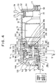
- a motor 300 has substantially the same constitution as the motor described in the first embodiment and comprises a cylindrical yoke 310, a plurality of field cores 321 and a stator coil 322 wound on the field core 321 constituting a stator 320 fixed on the inner face of this yoke 310 by a screw 311, an armature 330 provided inside the stator 320 and provided with a commutator 332 at one axial end thereof on which an armature coil 331 is wound, an armature shaft 340 for supporting the armature 330 and a brush mechanism 350 for supplying current to the commutator 332 of the armature 330.
- This brush mechanism 350 is constituted by a brush 351 which is in contact with the commutator 332, a brush holder 352 for holding this brush 351 and a brush spring 353 for pressing the brush 351 radially outwardly on the side of the commutator 332.
- One end of the armature shaft 340 is supported by a bearing 361 housed in a rear frame 360 coupled to one end of the yoke 310 using a faucet joint so that the armature shaft 340 can be rotated.
- the brush holder 352 is held between the rear frame 360 and the yoke 310.
- a sun gear 341 is formed at the other end of the armature shaft 340.
- the other end of the armature shaft 340 is supported by a bearing 371 housed in a front frame 370 coupled to the other end of the yoke 310 using a faucet joint so that the armature shaft 340 can be rotated. Further, the yoke 310 is held between the front frame 370 and the rear frame 360 and fixed firmly by a through bolt 380.
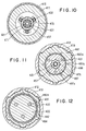
- a portion different in level 411 is respectively formed on the inner face at both ends of a cylindrical case 410 and six concave portions 412 are formed at an equal angular interval along the periphery thereof on the central inner face thereof as shown in Fig. 11 or 12.
- One end 421 of an output shaft 420 provided in the center of the case 410 is supported by a bearing 343 in the concave portion 342 formed at the other end of the armature shaft 340 so that the output shaft can be rotated and the output shaft 420 is arranged on the same axis as the armature shaft 340.
- a disc projection 422 integrated with the output shaft 420 is formed at one end 421 of the output shaft 420.
- a planetary gear 430 has its inside engaged with the sun gear 341 of the armature shaft 340 and has its periphery engaged with an internal gear formed on the inner face of a first rotator 440.
- a cylindrical part 442 extended on the side reverse to the side of the internal gear 441 on the peripheral side of which a conic slope 443 is formed and a flange part 444 extended on the peripheral side in the direction of the diameter thereof are integrated in the first rotator 440.
- the end of the flange part 444 is housed in the portion different in level 411 at one end of the case 410, and a plate 445 and a roller bearing 446 are housed in space formed among the portion different in level 411 of the case 410, the flange part 444 of the first rotator 440 and the front frame 370.
- the first rotator 440 is supported by the roller bearing 446 so that the first rotator can be rotated.
- the planetary gear 430 is attached to one end of a supporting pin 431 and a gear 432 is formed at the other end thereof.
- This supporting pin 431 is supported by the disc projection 422 of the output shaft 420 via the bearing 433 so that the supporting pin can be rotated.
- Three supporting pins 433 are provided at an equal interval along the periphery of the output shaft as shown in Figs. 10 to 12 and respectively support three planetary gears 430 so that any planetary gear can be rotated.
- An external gear 451 engaged with the inside of the gear 432 in the direction of the diameter thereof formed at the other end of the supporting pin 431 is formed inside a second rotator 450.
- a cylindrical part 452 which is extended on the side of the cylindrical part 442 of the first rotator 440 and on the peripheral side of which a conic slope 453 is formed and a flange part 454 extended on the peripheral side in the direction of the diameter thereof are integrated on the peripheral side of the second rotator 450.
- this flange part 454 is housed in the portion different in level 411 at the other end of the case 410, and a plate 455 and a roller bearing 456 are housed in space formed among the portion different in level 411 of the case 410, the flange part 454 of the second rotator 450 and a bracket 460.
- the second rotator 450 is supported by this roller bearing 456 and a bearing 457 so that the second rotator can be rotated as the first rotator 440.
- a rotation transmitting mechanism 470 comprises a first cylindrical part 471 extended axially along the output shaft 420 with a predetermined gap between the first cylindrical part and the output shaft and a disc part 472 extended from the first cylindrical part 471 to the cylindrical part 452 of the second rotator 450 and a longitudinal hole 473 through which the supporting pin 431 passes as shown in Fig. 10 is formed through this disc part 472.
- a second cylindrical part 474 which is extended from the disc part 472 to the disc projection 422 of the output shaft 420, on the inner face of which a difference in level 475 is formed and on the periphery of which a helical spline 476 is formed is integrated.
- a bearing 477 is provided in the difference in level 475 of the second cylindrical part 474 and the rotation transmitting mechanism 470 is supported so that the mechanism can be rotated independent of the output shaft 420.
- a regulating mechanism 480 comprises a regulating member 481 provided in the case 410 and this regulating member 481 comprises a circular part 482 extended axially and a protruded part 483 extended from this circular part 482 to the inside.
- a projection 482a fitted into the concave portion 412 of the case 410 is formed on the periphery of the circular part 482. The regulating member 481 can be moved axially without being rotated between the concave portion 412 of the case 410 and the projection 482a.
- First and second housings 482b and 482c for respectively housing a first ball 484 and a second ball 485 are formed in a position respectively opposite to the slope 443 of the cylindrical part 442 of the first rotator 440 and the slope 453 of the cylindrical part 452 of the second rotator 450 inside the circular part 482. Further, a through hole 483a extended axially is formed through the protruded part 483 of the regulating member 481 and a third ball 486 is housed in this through hole 483a.
- a moving member 487 is provided with a spline 487a fitted to the helical spline 476 of the second cylindrical part 474 of the rotation transmitting mechanism 470 inside and is fixed to the supporting pin 431.
- a housing 487b for housing the protruded part 483 of the regulating member 481 and the third ball 486 is formed outside this moving member 487.
- a coupling member 500 transmits the rotation of a stub axle 620 to the rotation reversing mechanism 400 and also transmits the rotation of the motor 300 to the pinion shaft 610.
- This coupling member 500 comprises a housing 510, a first bevel gear 520 supported in this housing 510 via a first bearing 511 so that the first bevel gear can be rotated and a second bevel gear 530 supported via a second bearing 512 so that the second bevel gear can be rotated.
- the other end 423 of the output shaft 420 is press-fitted into the concave portion 521 of the first bevel gear 520.
- a first gear 540 is fixed on the periphery of the rotation transmitting mechanism 470 on the side of the first bevel gear 520 and further, a second gear 550 engaged with the first gear 540 is fixed in the concave portion 531 of the second bevel gear 530.
- a steering shaft mechanism 600 comprises the pinion shaft 610 coupled to vehicle wheels not shown, the stub axle 620 coupled to a steering wheel not shown and a torsion bar 630 inserted into the concave portion 611 of the pinion shaft 610 and into the concave portion 621 of the stub axle 620, and both ends of this torsion bar 630 are respectively fixed on the pinion shaft 610 and stub axle 620 by pins 612 and 622.
- the pinion shaft 610 and the stub axle 620 are supported by a bearing 640 so that they can be rotated relatively.
- a first disc gear 650 engaged with the first bevel gear 520 of the coupling member 500 is provided on the periphery of the pinion shaft 610 so that the rotation of the motor 300 is transmitted to the pinion shaft 610.
- a second disc gear 660 engaged with the first bevel gear 520 of the coupling member 500 is provided on the periphery of the stub axle 620 so that the rotation of the stub axle 620 is transmitted to the second gear 550 via the second bevel gear 530.
- the housing 510 of the coupling member 500 is fixed to this case 670.
- the torsion bar 630 is twisted to rotate the stub axle 620 and the stub axle starts to rotate relative to the pinion shaft 610.
- the second disc gear 660 starts to be rotated in the same direction as the stub axle 620 by this rotation and the second bevel gear 530 is rotated in the direction shown by an arrow Y.
- the rotation transmitting mechanism 470 of the rotation reversing mechanism 400 is rotated via the second gear 550 and the first gear 540 by the rotation of this second bevel gear 530.
- the helical spline 476 of the second cylindrical part 474 is rotated by the rotation of the rotation transmitting mechanism 470 and the moving member 487 the spline 587a of which is coupled to this helical spline 476 is moved turning along the spline to the side of the motor 300.
- the regulating member 481 housed in the housing 487b of this moving member 487 is also moved axially by the movement of the moving member 487, the first ball 484 housed in the first housing 482b of the circular part 482 of the regulating member 481 comes in contact with and presses upon the slope 443 of the cylindrical part 442 of the first rotator 440, and as a result, the rotation of the first rotator 440 is regulated.
- Fig. 8 shows a state in which the rotation of the first rotator 440 is regulated.
- the rotation of the first rotator 440 is regulated, while the rotation of the second rotator 450 is not regulated because the regulating member 481 is moved to the side of the first rotator 440 and the second rotator 450 can be rotated owing to the roller bearing 456 and the bearing 457.
- An electric switch not shown is turned on by the axial movement of the moving member 487 to turn on the motor 300 and the armature shaft 340 is rotated in the direction shown by an arrow Z.
- the rotation of this armature shaft 340 is transmitted to the planetary gear 430 via the sun gear 341.
- the rotational speed of the armature shaft 340 is reduced in predetermined reduction gear ratio determined by the sun gear 341 and the internal gear 441 by the revolution of the planetary gear 430 and rotation in the same direction as the rotation of the armature shaft 340 is transmitted to the output shaft 420 via the supporting pin 431.
- the second rotator 450 provided with the external gear 451 engaged with the gear 432 formed at the other end of the supporting pin 431 is only rotated without being regulated.
- the rotation of the output shaft 420 is transmitted to the first bevel gear 520 and rotation in the same direction as the rotation of the stub axle 620 is transmitted to the pinion shaft 610 via the first disc gear 650.
- the rotational speed of the motor 300 is reduced and transmitted to the pinion shaft 610, and as a result, a wheel can be readily moved.
- the torsion bar 630 is twisted to rotate the stub axle 620.
- the stub axle 620 starts to be rotated relative to the pinion shaft 610
- the second disc gear 660 starts to be rotated in the same direction as the rotation of the stub axle 620
- the second bevel gear 530 is rotated in the direction reverse to the direction shown by the arrow Y.
- the rotation transmitting mechanism 470 of the rotation reversing mechanism 400 is rotated in the reverse direction via the second gear 550 and the first gear 540 by the rotation of this second bevel gear 530.
- the helical spline 476 of the second cylindrical part 474 is rotated by the rotation in the reverse direction of the rotation transmitting mechanism 470 and the moving member 487 the spline 487a of which is coupled to this helical spline 476 is moved along the spline turning not on the side of the motor 300 but on the side of the second rotator 450.
- the regulating member 481 housed in the housing 487b of this moving member 487 is also moved axially by the movement of the moving member 487 and the second ball 485 housed in the second housing 482c of the circular part 482 of the regulating member 481 comes in contact with the slope 453 of the cylindrical part 452 of the second rotator 450 and presses upon it, and as a result, the rotation of the second rotator 450 is regulated. It is because the rotation of the regulating member 481 is regulated as the projection 482a of this regulating member 481 is fitted into the concave portion 412 of the case 410.
- Fig. 9 shows a state in which the rotation of the second rotator 450 is regulated.
- the rotation of the second rotator 450 is regulated, while the rotation of the first rotator 440 is not regulated because the regulating member 481 is moved to the side of the second rotator 450 and the first rotator 440 can be rotated by the roller bearing 446 and the bearing 447.
- the electric switch not shown is turned on by the axial movement of the moving member 487 to turn on the motor 300 and the armature shaft 340 is rotated in the direction shown by the arrow Z (in Fig. 7) as described above.
- This rotation of the armature shaft 340 is transmitted to the planetary gear 340 via the sun gear 341.
- the first rotator is only rotated, however, as the rotation of the second rotator 450 is regulated, the supporting pin 431 provided with the gear 432 engaged with the external gear 451 of the second rotator 450 is rotated in the direction reverse to the rotational direction of the armature shaft 340.
- the rotational speed of the supporting pin is reduced in predetermined reduction gear ratio determined by the external gear 451 and the gear 432 of the second rotator 450 and rotation in the direction reverse to the rotational direction of the armature shaft 340 is transmitted to the output shaft 420 via the supporting pin 431.
- Predetermined reduction gear ratio determined by the external gear 451 of the second rotator 450 and the gear 432 and predetermined reduction gear ratio determined by the sun gear 341 and the internal gear 441 of the first rotator 440 are set to the same value. Therefore, this rotation is transmitted to the first bevel gear 520 by the rotation of the output shaft 420 and rotation in the same direction as the rotation of the stub axle 620 is transmitted to the pinion shaft 610 via the first disc gear 650.
- the rotational speed of the motor 300 is reduced, the reduced rotational speed is transmitted to the pinion shaft 610 and a wheel can be readily moved.
- the rotational direction of the output shaft 420 is switched by sensing the change of the rotational direction of a steering wheel (the rotational direction of the stub axle 620) by the movement of the regulating member 480 by the rotation of the rotation transmitting mechanism 470 as described above, the flow of current to the armature coil 331 of the motor 330 is not required to be switched and the armature reaction and the spark noise generation are suppressed.
- the torque of the output shaft 420 is transmitted to a steering side, it can be surely transmitted to the steering wheel without causing the delay in response by the armature reaction of the motor.
- the torque received from the output shaft 420 can be set according to a situation by differentiating predetermined reduction gear ratio determined by the external gear 451 of the second rotator 450 and the gear 432 and predetermined reduction gear ratio determined by the sun gear 341 and the internal gear 441 of the first rotator 440 in a predetermined range and for example, when torque is transmitted to a steering wheel, the load to a driver can be also reduced by changing the degree of assistance in the clockwise or counterclockwise rotational direction of the steering wheel in view of the road condition and the running condition such as turning to the left and turning to the right.
- the rotation of the first and second rotators 440 and 450 are not regulated when the steering device is in a neutral state, delay in return to the neutral position caused by the inertia of the armature generated in the output shaft 420 by a reduction gear can be eliminated by preventing the transmission of rotation between the armature shaft 340 and the output shaft 420 when a steering device is in neutral, and the steering can be returned promptly to a neutral position.
- the motor 300 may be also turned on not by the movement of the regulating member 481 but by a signal from a torque sensor or the like provided on a steering shaft or the like.
- the gear 432 may be mounted on the supporting pin 431 rotatably of fixedly.
Landscapes
- Engineering & Computer Science (AREA)
- Chemical & Material Sciences (AREA)
- Combustion & Propulsion (AREA)
- Transportation (AREA)
- Mechanical Engineering (AREA)
- Power Steering Mechanism (AREA)
- Steering Control In Accordance With Driving Conditions (AREA)
- Connection Of Motors, Electrical Generators, Mechanical Devices, And The Like (AREA)
- Structure Of Transmissions (AREA)
Claims (11)
- Moteur pour un dispositif de direction assistée destiné à transmettre la rotation à un pignon arbré accouplé à des roues de véhicule, comprenant :caractérisé en ce queun induit (30, 330) avec un noyau d'induit et une bobine d'induit ;un arbre d'induit (40, 340) destiné à supporter ledit induit ;un arbre de sortie (70, 420) destiné à transmettre la rotation dudit arbre d'induit audit pignon arbré ; etdes moyens d'inversion (144, 234, 400, 500) prévus entre ledit arbre d'induit et ledit arbre de sortie afin de faire tourner ledit arbre de sortie dans deux sens inverses par rapport à la rotation dudit arbre d'induit dans un sens conforme au sens de rotation dudit pignon arbré, réduisant la vitesse de rotation dudit arbre d'induit,
lesdits moyens d'inversion comprennent un mécanisme de réduction à engrenages possédant :dans lequel ledit arbre de sortie est prévu en une position centrale autour de laquelle tournent lesdits arbres de planétaires,un premier solaire (42) formé sur ledit arbre d'induit ;une pluralité de premiers planétaires (91) engrenant avec ledit premier solaire afin de tourner autour dudit premier solaire ;une roue à denture interne (110) présentant des dents intérieures engrenant avec lesdits premiers planétaires ;un deuxième planétaire (92) intégré en rotation sur le même axe que lesdits premiers planétaires ;un deuxième solaire (201) présentant des dents externes engrenant avec ledit deuxième planétaire ; etdes arbres de planétaires (73) destinés à supporter sur eux lesdits premiers et deuxième planétaire de façon rotative, et
dans lequel lesdits moyens d'inversion sont construits afin de :ajuster la rotation de ladite roue à denture interne (110) et de permettre la rotation dudit deuxième solaire (201) dans le cas où la rotation dans le même sens que la rotation dudit arbre d'induit (40, 340) doit être transmise audit arbre de sortie (70, 420) ; etajuster la rotation dudit deuxième solaire (201) et de permettre la rotation de ladite roue à denture interne (110) dans le cas où la rotation dans le sens inverse à la rotation dudit arbre d'induit (40, 340) doit être transmise audit arbre de sortie (70, 420). - Moteur pour un dispositif de direction assistée selon la revendication 1, dans lequel ledit moyen d'inversion inverse la rotation dudit arbre de sortie (70, 420) sur la base du couple dans le sens de rotation agissant sur ledit arbre de sortie ou de l'angle de rotation.
- Moteur pour un dispositif de direction assistée selon la revendication 1 ou 2, dans lequel lesdits moyens d'inversion ont deux rapports de réduction d'engrenages différents, un dont la rotation dans le même sens que la rotation dudit arbre d'induit (40, 340) est transmise audit arbre de sortie (70, 420) et un autre dont la rotation en sens inverse de la rotation dudit arbre d'induit (40, 340) est transmise audit arbre de sortie (70, 420).
- Moteur pour un dispositif de direction assistée selon la revendication 1 ou 2, dans lequel lesdits moyens d'inversion ont deux rapports de réduction d'engrenages sensiblement identiques, un dont la rotation dans le même sens que la rotation dudit arbre d'induit (40, 340) est transmise audit arbre de sortie (70, 420) et un autre dont la rotation en sens inverse de la rotation dudit arbre d'induit (40, 340) est transmise audit arbre de sortie (70, 420).
- Moteur pour un dispositif de direction assistée selon l'une des revendications 1 à 4, dans lequel ledit moyen d'inversion est construit de façon à interrompre la transmission de la rotation entre ledit arbre d'induit (40, 340) et ledit arbre de sortie (70, 420)lorsque ladite direction est dans une position prédéterminée.
- Moteur pour un dispositif de direction assistée destiné à transmettre la rotation à un pignon arbré accouplé aux roues du véhicule, comprenant :caractérisé en ce queun induit (30, 330) avec un noyau d'induit et une bobine d'induit ;un arbre d'induit (40, 340) destiné à supporter ledit induit ;un arbre de sortie (70, 420) destiné à transmettre la rotation dudit arbre d'induit audit pignon arbré ; etdes moyens d'inversion (144, 234, 400, 500) prévus entre ledit arbre d'induit et ledit arbre de sortie afin de faire tourner ledit arbre de sortie dans deux sens différents par rapport à la rotation dudit arbre d'induit dans un sens dépendant du sens de rotation dudit pignon arbré, réduisant la vitesse de rotation dudit arbre d'induit,
lesdits moyens d'inversion ont deux rapports de réduction d'engrenages différents, un dont la rotation dans le même sens que la rotation dudit arbre d'induit (40, 340) est transmise audit arbre de sortie (70, 420) et un autre dont la rotation dans le sens inverse de la rotation dudit arbre d'induit (40, 340) est transmise audit arbre de sortie (70, 420). - Dispositif de direction assistée comprenant :une fusée (620) accouplée à une direction ;un pignon arbré (610) accouplé aux roues du véhicule ;une barre de torsion (630) reliant ladite fusée et ledit pignon arbré ;un moteur (300) pourvu d'un induit (330) avec un noyau d'induit et une bobine d'induit et d'un arbre d'induit (340) ;un arbre de sortie (420) destiné à transmettre la rotation de l'arbre d'induit dudit moteur audit pignon arbré ; etdes moyens d'inversion (400, 500) destinés à détecter la rotation relative entre ladite fusée et ledit pignon arbré et à faire tourner ledit arbre de sortie dans deux sens par rapport à la rotation dudit induit dans un sens dépendant du sens de rotation de ladite; caractérisé en ce quelesdits moyens d'inversion (400, 500) sont prévus entre ledit arbre d'induit et ledit arbre de sortie et comprennent un mécanisme de réduction à engrenages possédant :un solaire (341) prévu sur ledit arbre d'induit ;une pluralité de planétaires (430) engrenant avec ledit solaire et tournant autour dudit solaire ;un axe support (431) destiné à supporter la rotation desdits planétaires et transmettant la rotation audit arbre de sortie ;une roue à denture interne (441) présentant des dents intérieures engrenant avec lesdits planétaires ;une roue d'engrenage (432) montée sur ledit axe support ; etune roue à denture externe (451) engrenant avec ladite roue d'engrenage sur ledit axe support.
- Dispositif de direction assistée selon la revendication 7, comprenant de plus :un élément d'ajustement (480) destiné à ajuster soit la rotation de ladite roue à denture interne (441) soit celle de ladite roue à denture externe (451) au niveau dudit moyen d'inversion de façon à changer le sens de la rotation transmise dudit arbre d'induit audit arbre de sortie.
- Dispositif de direction assistée selon la revendication 8 dans lequel ledit élément d'ajustement (480) est déplacé afin d'ajuster soit la rotation de ladite roue à denture interne (441) soit celle de ladite roue à denture externe (451) conformément à la rotation relative entre ladite fusée (620) et ledit pignon arbré (610).
- Dispositif de direction assistée selon la revendication 9, comprenant de plus :un élément de transmission de la rotation (470) prévu sur la périphérie dudit arbre de sortie (420) afin de transmettre la rotation de ladite fusée (620) ; etun accouplement à cannelures hélicoïdales (476) prévu entre ledit élément de transmission de la rotation (470) et ledit élément d'ajustement (480) afin de changer le sens du mouvement dudit élément d'ajustement conformément au sens de rotation dudit élément de transmission de la rotation (470) et à ajuster la rotation de ladite roue à denture interne (441) ou celle de ladite roue à denture externe(451).
- Dispositif de direction assistée selon l'une quelconque des revendications 7 à 10, dans lequel on empêche la transmission de la rotation entre ledit arbre d'induit (340) et ledit arbre de sortie (420) lorsque la différence relative d'angle de rotation entre ladite fusée (620)et ledit pignon arbré (610) est dans une plage de valeurs prédéterminée.
Applications Claiming Priority (6)
| Application Number | Priority Date | Filing Date | Title |
|---|---|---|---|
| JP33025995 | 1995-12-19 | ||
| JP33025995 | 1995-12-19 | ||
| JP330259/95 | 1995-12-19 | ||
| JP279561/96 | 1996-10-22 | ||
| JP8279561A JPH09226607A (ja) | 1995-12-19 | 1996-10-22 | パワーステアリング装置用電動機およびこの電動機を用いたパワーステアリング装置 |
| JP27956196 | 1996-10-22 |
Publications (3)
| Publication Number | Publication Date |
|---|---|
| EP0780281A2 EP0780281A2 (fr) | 1997-06-25 |
| EP0780281A3 EP0780281A3 (fr) | 1998-07-01 |
| EP0780281B1 true EP0780281B1 (fr) | 2002-03-13 |
Family
ID=26553386
Family Applications (1)
| Application Number | Title | Priority Date | Filing Date |
|---|---|---|---|
| EP96120273A Expired - Lifetime EP0780281B1 (fr) | 1995-12-19 | 1996-12-17 | Moteur électrique pour direction assistée et direction assistée utilisant ce moteur |
Country Status (4)
| Country | Link |
|---|---|
| US (1) | US5927428A (fr) |
| EP (1) | EP0780281B1 (fr) |
| JP (1) | JPH09226607A (fr) |
| DE (1) | DE69619776T2 (fr) |
Families Citing this family (9)
| Publication number | Priority date | Publication date | Assignee | Title |
|---|---|---|---|---|
| DE19743961A1 (de) * | 1997-10-04 | 1999-04-15 | Mercedes Benz Lenkungen Gmbh | Lenkhelfeinrichtung für ein Kraftfahrzeug |
| DE59901957D1 (de) * | 1998-08-15 | 2002-08-08 | Krupp Presta Ag Eschen | Elektrisch unterstützte lenkhilfe mit kompaktem planetengetriebe |
| DE10342681B3 (de) * | 2003-09-16 | 2005-04-21 | Thyssenkrupp Automotive Ag | Fahrzeuglenkung mit einer Übersetzungsverhältnisänderungseinrichtung |
| JP2005221053A (ja) * | 2004-02-09 | 2005-08-18 | Hitachi Ltd | 動力伝達装置および車両の操舵装置 |
| US6978860B2 (en) * | 2004-04-01 | 2005-12-27 | Delphi Technologies, Inc. | Method and system for electric power steering |
| US20060042861A1 (en) * | 2004-08-24 | 2006-03-02 | Ovshinsky Stanford R | Steering assist mechanism |
| MX2008014783A (es) | 2008-02-05 | 2009-08-27 | Krueger Int Inc | Armazon para silla con soporte hueco ergonomico integral. |
| CN107104546B (zh) * | 2017-05-25 | 2025-02-18 | 盟立自动化科技(上海)有限公司 | 具有手动和电动离合装置的电动机 |
| US12509337B2 (en) | 2023-04-13 | 2025-12-30 | Crown Equipment Corporation | Steering shaft assembly for a materials handling vehicle |
Family Cites Families (9)
| Publication number | Priority date | Publication date | Assignee | Title |
|---|---|---|---|---|
| FR2492759A1 (fr) * | 1980-10-27 | 1982-04-30 | Citroen Sa | Perfectionnements apportes aux mecanismes d'assistance rotative, notamment pour direction de vehicule |
| JPS6020746A (ja) * | 1983-07-09 | 1985-02-02 | Matsushita Electric Ind Co Ltd | 逆転機構内蔵クラツチ付電動機 |
| JPS638071A (ja) * | 1986-06-25 | 1988-01-13 | Hitachi Ltd | 電動式パワ−ステアリング装置 |
| JPH037661A (ja) * | 1989-06-03 | 1991-01-14 | Hitachi Ltd | 電動パワーステアリング装置 |
| JPH06316270A (ja) | 1992-12-16 | 1994-11-15 | Omron Corp | 電動式パワーステアリング装置 |
| JPH0761362A (ja) * | 1993-08-25 | 1995-03-07 | Kayaba Ind Co Ltd | パワーステアリング装置 |
| JP3007661U (ja) | 1994-08-09 | 1995-02-21 | 有限会社長良化成産業 | エアコン室外機取付台用取付板 |
| DE4438930C1 (de) * | 1994-10-31 | 1995-10-26 | Daimler Benz Ag | Zahnstangenlenkung bzw. -steuerung mit Servomotor |
| US5732791A (en) * | 1995-11-30 | 1998-03-31 | Trw Inc. | Steering apparatus |
-
1996
- 1996-10-22 JP JP8279561A patent/JPH09226607A/ja active Pending
- 1996-12-17 EP EP96120273A patent/EP0780281B1/fr not_active Expired - Lifetime
- 1996-12-17 DE DE69619776T patent/DE69619776T2/de not_active Expired - Lifetime
- 1996-12-18 US US08/768,928 patent/US5927428A/en not_active Expired - Lifetime
Also Published As
| Publication number | Publication date |
|---|---|
| EP0780281A2 (fr) | 1997-06-25 |
| DE69619776D1 (de) | 2002-04-18 |
| DE69619776T2 (de) | 2002-11-14 |
| EP0780281A3 (fr) | 1998-07-01 |
| US5927428A (en) | 1999-07-27 |
| JPH09226607A (ja) | 1997-09-02 |
Similar Documents
| Publication | Publication Date | Title |
|---|---|---|
| JP4461582B2 (ja) | 駆動力切換機構 | |
| US6026925A (en) | Electrically driven power assisting device | |
| EP0780281B1 (fr) | Moteur électrique pour direction assistée et direction assistée utilisant ce moteur | |
| JP3217497B2 (ja) | 後輪操舵装置の中立復帰機構 | |
| JPH10297313A (ja) | 駆動力切換機構 | |
| JPH084383Y2 (ja) | 車両用操蛇装置 | |
| JPH08258728A (ja) | 電動パワーステアリング装置 | |
| JPS6137581A (ja) | 電動式動力舵取り装置 | |
| US20240034392A1 (en) | Vehicle steering apparatus | |
| US20220258791A1 (en) | Automobile steering apparatus | |
| JP3658683B2 (ja) | 電動式舵取装置 | |
| JP2743354B2 (ja) | 2輪・4輪駆動切換装置 | |
| JP4678524B2 (ja) | 車両用操舵装置 | |
| JPH1134888A (ja) | 電動式パワーステアリング装置 | |
| JP4104346B2 (ja) | 車両用後輪操舵装置 | |
| JP2002154443A (ja) | 電動パワーステアリング装置 | |
| JP3458867B2 (ja) | 電動式パワーステアリング装置 | |
| JPH04310475A (ja) | 電動式動力舵取装置 | |
| KR100754495B1 (ko) | 전동 파워 스티어링 시스템의 모터장치 | |
| JP2004299476A (ja) | 駆動力切換機構 | |
| JP2664226B2 (ja) | クラッチ装置 | |
| KR100356664B1 (ko) | 자동차용 조향 시스템의 기어비 변경 장치 | |
| JP4453241B2 (ja) | 駆動力切換機構 | |
| JPH0224686B2 (fr) | ||
| JP2667869B2 (ja) | 電動式パワーステアリング装置 |
Legal Events
| Date | Code | Title | Description |
|---|---|---|---|
| PUAI | Public reference made under article 153(3) epc to a published international application that has entered the european phase |
Free format text: ORIGINAL CODE: 0009012 |
|
| AK | Designated contracting states |
Kind code of ref document: A2 Designated state(s): DE FR GB IT |
|
| PUAL | Search report despatched |
Free format text: ORIGINAL CODE: 0009013 |
|
| AK | Designated contracting states |
Kind code of ref document: A3 Designated state(s): DE FR GB IT |
|
| 17P | Request for examination filed |
Effective date: 19980730 |
|
| 17Q | First examination report despatched |
Effective date: 19991217 |
|
| GRAG | Despatch of communication of intention to grant |
Free format text: ORIGINAL CODE: EPIDOS AGRA |
|
| GRAG | Despatch of communication of intention to grant |
Free format text: ORIGINAL CODE: EPIDOS AGRA |
|
| GRAH | Despatch of communication of intention to grant a patent |
Free format text: ORIGINAL CODE: EPIDOS IGRA |
|
| GRAH | Despatch of communication of intention to grant a patent |
Free format text: ORIGINAL CODE: EPIDOS IGRA |
|
| REG | Reference to a national code |
Ref country code: GB Ref legal event code: IF02 |
|
| GRAA | (expected) grant |
Free format text: ORIGINAL CODE: 0009210 |
|
| AK | Designated contracting states |
Kind code of ref document: B1 Designated state(s): DE FR GB IT |
|
| REF | Corresponds to: |
Ref document number: 69619776 Country of ref document: DE Date of ref document: 20020418 |
|
| ET | Fr: translation filed | ||
| PLBE | No opposition filed within time limit |
Free format text: ORIGINAL CODE: 0009261 |
|
| STAA | Information on the status of an ep patent application or granted ep patent |
Free format text: STATUS: NO OPPOSITION FILED WITHIN TIME LIMIT |
|
| 26N | No opposition filed |
Effective date: 20021216 |
|
| REG | Reference to a national code |
Ref country code: GB Ref legal event code: 746 Effective date: 20030725 |
|
| PGFP | Annual fee paid to national office [announced via postgrant information from national office to epo] |
Ref country code: FR Payment date: 20101224 Year of fee payment: 15 |
|
| PGFP | Annual fee paid to national office [announced via postgrant information from national office to epo] |
Ref country code: GB Payment date: 20101215 Year of fee payment: 15 |
|
| PGFP | Annual fee paid to national office [announced via postgrant information from national office to epo] |
Ref country code: IT Payment date: 20101217 Year of fee payment: 15 Ref country code: DE Payment date: 20101215 Year of fee payment: 15 |
|
| GBPC | Gb: european patent ceased through non-payment of renewal fee |
Effective date: 20111217 |
|
| REG | Reference to a national code |
Ref country code: FR Ref legal event code: ST Effective date: 20120831 |
|
| REG | Reference to a national code |
Ref country code: DE Ref legal event code: R119 Ref document number: 69619776 Country of ref document: DE Effective date: 20120703 |
|
| PG25 | Lapsed in a contracting state [announced via postgrant information from national office to epo] |
Ref country code: GB Free format text: LAPSE BECAUSE OF NON-PAYMENT OF DUE FEES Effective date: 20111217 Ref country code: DE Free format text: LAPSE BECAUSE OF NON-PAYMENT OF DUE FEES Effective date: 20120703 |
|
| PG25 | Lapsed in a contracting state [announced via postgrant information from national office to epo] |
Ref country code: IT Free format text: LAPSE BECAUSE OF NON-PAYMENT OF DUE FEES Effective date: 20111217 |
|
| PG25 | Lapsed in a contracting state [announced via postgrant information from national office to epo] |
Ref country code: FR Free format text: LAPSE BECAUSE OF NON-PAYMENT OF DUE FEES Effective date: 20120102 |