EP0780941B1 - Stabisolator mit einem Unterbrecher für Hochspannung und wenigstens einem Messtransformator - Google Patents
Stabisolator mit einem Unterbrecher für Hochspannung und wenigstens einem Messtransformator Download PDFInfo
- Publication number
- EP0780941B1 EP0780941B1 EP95120383A EP95120383A EP0780941B1 EP 0780941 B1 EP0780941 B1 EP 0780941B1 EP 95120383 A EP95120383 A EP 95120383A EP 95120383 A EP95120383 A EP 95120383A EP 0780941 B1 EP0780941 B1 EP 0780941B1
- Authority
- EP
- European Patent Office
- Prior art keywords
- rod insulator
- tube
- transformer
- interrupter according
- insulator
- Prior art date
- Legal status (The legal status is an assumption and is not a legal conclusion. Google has not performed a legal analysis and makes no representation as to the accuracy of the status listed.)
- Expired - Lifetime
Links
- 239000012212 insulator Substances 0.000 claims abstract description 29
- 238000004804 winding Methods 0.000 claims abstract description 19
- 238000009413 insulation Methods 0.000 claims abstract description 8
- 239000002184 metal Substances 0.000 claims abstract description 6
- 239000004020 conductor Substances 0.000 claims description 2
- 230000001939 inductive effect Effects 0.000 claims description 2
- 238000000926 separation method Methods 0.000 claims description 2
- 230000009466 transformation Effects 0.000 claims description 2
- 230000009977 dual effect Effects 0.000 claims 1
- 230000007246 mechanism Effects 0.000 abstract 1
- 238000004519 manufacturing process Methods 0.000 description 4
- 238000009826 distribution Methods 0.000 description 3
- 238000000034 method Methods 0.000 description 3
- 238000010276 construction Methods 0.000 description 2
- 238000001035 drying Methods 0.000 description 2
- 238000005470 impregnation Methods 0.000 description 2
- 239000011810 insulating material Substances 0.000 description 2
- 239000002985 plastic film Substances 0.000 description 2
- 229920006255 plastic film Polymers 0.000 description 2
- 238000003860 storage Methods 0.000 description 2
- NMFHJNAPXOMSRX-PUPDPRJKSA-N [(1r)-3-(3,4-dimethoxyphenyl)-1-[3-(2-morpholin-4-ylethoxy)phenyl]propyl] (2s)-1-[(2s)-2-(3,4,5-trimethoxyphenyl)butanoyl]piperidine-2-carboxylate Chemical compound C([C@@H](OC(=O)[C@@H]1CCCCN1C(=O)[C@@H](CC)C=1C=C(OC)C(OC)=C(OC)C=1)C=1C=C(OCCN2CCOCC2)C=CC=1)CC1=CC=C(OC)C(OC)=C1 NMFHJNAPXOMSRX-PUPDPRJKSA-N 0.000 description 1
- 238000006243 chemical reaction Methods 0.000 description 1
- 238000001514 detection method Methods 0.000 description 1
- 238000006073 displacement reaction Methods 0.000 description 1
- 239000012774 insulation material Substances 0.000 description 1
Images


Classifications
-
- H—ELECTRICITY
- H02—GENERATION; CONVERSION OR DISTRIBUTION OF ELECTRIC POWER
- H02B—BOARDS, SUBSTATIONS OR SWITCHING ARRANGEMENTS FOR THE SUPPLY OR DISTRIBUTION OF ELECTRIC POWER
- H02B13/00—Arrangement of switchgear in which switches are enclosed in, or structurally associated with, a casing, e.g. cubicle
- H02B13/02—Arrangement of switchgear in which switches are enclosed in, or structurally associated with, a casing, e.g. cubicle with metal casing
- H02B13/035—Gas-insulated switchgear
- H02B13/0356—Mounting of monitoring devices, e.g. current transformers
-
- H—ELECTRICITY
- H01—ELECTRIC ELEMENTS
- H01H—ELECTRIC SWITCHES; RELAYS; SELECTORS; EMERGENCY PROTECTIVE DEVICES
- H01H33/00—High-tension or heavy-current switches with arc-extinguishing or arc-preventing means
- H01H33/02—Details
- H01H33/027—Integrated apparatus for measuring current or voltage
Definitions
- the above invention relates to a rod insulator according to the preamble of claim 1 with a breaker for high voltage, which is insulated with the aid of a gas and has breakers in SF 6 insulation and measuring transformers (cf. GB-A-1 112 112).
- a breaker In substations for the distribution of electrical energy a breaker is assigned to each rod insulator Current transformers (TA) are assigned and voltage transformers (TV) for measuring the electrical current and the electrical voltage, as well as to supply the Safety devices.
- TA rod insulator Current transformers
- TV voltage transformers
- the transformers are for each isolator of a line and the breaker is mounted on separate brackets, this leads to a considerable space requirement and one great design effort for the substation.
- the object of the above invention is to avoid the disadvantages of the prior art and to reduce the dimensions and the construction costs for a transformer station AT, using measuring transformers (both TA and TV) which are gas-insulated SF 6 and a current transformer ( TA) and / or have a voltage transformer (TV), the transformer (TA / TV) being installed in the rod insulator, which accommodates an interrupter in SF 6 construction.
- measuring transformers both TA and TV
- TA current transformer
- TV voltage transformer
- the solution proposed according to the invention allows the Disadvantages of the prior art, especially one Avoid insulation using oil paper and the opportunity to create complex winding processes using oil paper or plastic films dispense. Furthermore, there are no drying processes or Impregnation processes taking place under vacuum more required. Furthermore, the invention principally partial discharges due to non-uniformity of the layered insulation material avoided.
- the manufacturing process is common to a few Assembly operations limited together with assembly of the rod insulator are feasible and constant Enable manufacturing processes with a minimum of time.
- the performance features and the manufacturing processes for the Rod insulator according to the invention essentially correspond those of the independent transformers TA and TV.
- gaseous insulating material ensures that due to mobility and Adaptability of the dielectric automatically Resetting the dielectric insulation also in Zones of a non-uniform local course occurs.
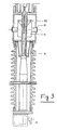
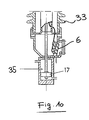
- the rod insulator and breaker (TA) in three components be divided into a break chamber with an interrupter, the chamber being only partially in is shown in the figures, in a zone 31, the one Current transformer TA accommodates and in a housing 32, the Means for actuating the movable contacts of the chamber and has clamps.
- the interrupter chamber has two in a known manner movable contacts, the lower contact 34 is partially shown in the figures. Because the chamber and the movable contacts essentially the Devices corresponding to known devices are on their more precise presentation has been omitted.
- the housing 32 takes a crank 8 for actuating the movable contacts on a rod 8a, the Insulating body 33 penetrates, can be actuated.
- the Insulating body 33 can also be actuated via a hydraulic cylinder 35, which receives a movable piston 17 take place.
- a Measuring transformer 31 (in the example shown Transformer TA) provided and according to the invention educated.
- the electromagnetic part TA consists of one or several nuclei and is toroidal inside trained shield 1 arranged.
- Figures 1 and 2 is a single transformer TA provided and the location of a possible second Transformer, which has a similar structure, is shown in Fig. 1 and 2 indicated by dashed lines.
- the secondary windings 2 of the core are over one Metal tube 3 connected to ground.
- the metal tube 3 has high Rigidity and axially penetrates the rod insulator 33.
- the tube has a rod 4, as well as the lines of the windings, the end pieces of which are sealed by means of insulating bodies 6 from the chamber which receives the insulating gas SF 6 .
- the core 1 is arranged tangentially to the tube 3.
- the metal tube 3 In addition to a holder in the housing 7, the metal tube 3 also from a fixed insulating tube 19 held. This tube 19 is on its top from Flange 18 held.
- the primary winding consists of a conductive tube 9 which is arranged in a horizontal position, furthermore rods 10 and conductor rods 11 are provided which are arranged in the interior of the tube 9.
- the rods 10 are connected to the ends of the tube 9.
- the pipe 9 creates a separation between the inside of the transformer, which receives the gas SF 6 , and the inside of the pipe, which is under atmospheric pressure.
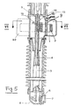
- the primary winding is electrical with the housing and thus connected to the interrupter pole via a switch 12 and protrudes with the outer extension 13 (see Fig. 5) an isolated switching device 14 in connection.
- a voltage distribution system is also used suggested both inside and outside of the Transformer TA. More specifically, it is an annular one Shield 15 for distributing the voltage along the Insulating rod 5 and the insulating tube 4 provided as well as a tubular shield 16 for splitting the voltage along the insulator 33.
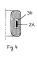
- Fig. 4 shows in section the core, the so-called Rogowsky coil 2a which has a capacitive sensor 36 for a simultaneous detection of the current and the Has tension.
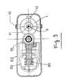
- 5 to 7 is a modified embodiment of the Invention shown in this drawing were the same reference numerals as in Figures 1 to 3 for identifying identical or corresponding components used.
- the main difference compared to the Embodiments according to FIGS. 1 to 3 consists in the Arrangement of the tangential core in one horizontal plane, i.e. with arrangement of the axial tube 9 in a vertical arrangement. With dashed lines the The location of a (possible) second core B2 is illustrated.
- a current transformer (of the type shown in FIGS. 1 to 3 or 5 to 7) is assigned an inductive voltage transformer TV, which is designed in SF 6 insulation and is identified by the reference symbol B3 in FIGS. 8 and 9.
- the part of the transformer B3 connected to ground is mechanically fastened to the position securing tube 3.
- the electromagnetic part of the transformer TV consists of a core 20 on which one or more secondary windings 21 are arranged, which are connected to ground via the metal tube 3 and with the housing of the terminals 7 via insulated passages 6, which are sealed off from the gas SF 6 are connected.
- the primary winding 23 is completely shielded and with connected to the live part via a spring 24.
- the shield 22 enables a better distribution of the Tension between primary part and secondary part.
Landscapes
- Engineering & Computer Science (AREA)
- Power Engineering (AREA)
- Transformers For Measuring Instruments (AREA)
- Testing Relating To Insulation (AREA)
Description
Claims (12)
- Stabisolator (33) einem Unterbrecher für Hochspannung und wenigstens einem Meßtransformator, in SF6-Isolierung, wobei der Stabisolator (33) einen in SF6 isolierten Stromtransformator aufnimmt, der in den Stabisolator (33) eingesetzt ist und wenigstens einen magnetischen Kern aufweist, der an Masse gelegt ist in eine toroidale Abschirmung (1) eingesetzt ist, die in ihrem Inneren die Sekundärwicklungen (2) aufnimmt, wobei
eine Primärwicklung vorgesehen ist, die axial im Inneren des toroidal ausgebildeten Kernes angeordnet ist dadurch gekennzeichnet , daß der Transformator zwischen einer Kammer (30) und Antriebsmitteln angeordnet ist, daß der magnetische Kern von einem Metallrohr (3) mit hoher Steifigkeit gehalten wird und tangential gegenüber dem Rohr (3) angeordnet ist, daß die Primärwicklung aus einem leitenden Rohr (9) besteht, und Leiterstangen (11) aufweist, die im Inneren des Rohres (9) angeordnet sind, und mit Stangen (10) versehen ist, die am Ende des Rohrs (9) verbunden sind. - Stabisolator mit einem Unterbrecher nach Patentanspruch 1, dadurch gekennzeichnet, daß das Leitungsrohr (9) eine Trennung zwischen der inneren Zone des Transformators, der das Isoliergas SF6 aufnimmt, und dem Inneren des Rohres (9), welches unter atmosphärischem Druck steht, schafft.
- Stabisolator für einen Unterbrecher nach Patentanspruch 1 oder 2, dadurch gekennzeichnet , daß die Primärwicklung elektrisch mit dem Gehäuse und dem Unterbrecherpol über einen ersten Schalter (12) und am äußeren Fortsatz (13) über einen zweiten Schalter (14) verbunden ist, um an der Primärwicklung eine Änderung des Transformationsverhältnisses zu erlauben.
- Stabisolator für einen Unterbrecher nach Patentanspruch 1 bis 3, dadurch gekennzeichnet , daß eine ringförmige Abschirmung (15) vorgesehen ist, mit der ein Aufteilen der Spannung entlang der Isolierstange (5) und dem Isolierrohr (4) erfolgt.
- Stabisolator für einen Unterbrecher nach Patentanspruch 1 bis 3, dadurch gekennzeichnet , daß eine rohrförmige Abschirmung (16) zum Verteilen der Spannung entlang dem Isolator (33) vorgesehen ist.
- Stabisolator für einen Unterbrecher nach Patentanspruch 1 bis 5, dadurch gekennzeichnet , daß der tangential angeordnete Kern in einer horizontalen Ebene angeordnet ist.
- Stabisolator für einen Unterbrecher nach Patentanspruch 1 bis 5, dadurch gekennzeichnet , daß der tangential angeordnere Kern in einer vertikalen Ebene angeordnet ist.
- Stabisolator für einen Unterbrecher nach Patentanspruch 1 bis 7, dadurch gekennzeichnet , daß zwei Meßtransformatoren in Zweieranordnung vorgesehen sind.
- Stabisolator für einen Unterbrecher nach Patentanspruch 8, dadurch gekennzeichnet , daß beide Transformatoren als Stromtransformatoren (TA) ausgebildet sind.
- Stabisolator für einen Unterbrecher nach Patentanspruch 8, dadurch gekennzeichnet , daß beide Transformatoren als Spannungstransformatoren (TV) ausgebildet sind.
- Stabisolator für einen Unterbrecher nach Patentanspruch 8, dadurch gekennzeichnet , daß einer der Transformatoren als Stromtransformator (TA) und der andere Transformator als induktiver Spannungstransformator (TV) ausgebildet ist.
- Stabisolator für einen Unterbrecher nach Patentanspruch 1 bis 5, dadurch gekennzeichnet , daß der Kern eine Rogowsky-Spule (2A) aufnimmt, die mit einem kapazitiv arbeitenden Sensor zum gleichzeitigen Erfassen des elektrischen Stromes und der elektrischen Spannung aufweist.
Priority Applications (5)
| Application Number | Priority Date | Filing Date | Title |
|---|---|---|---|
| AT95120383T ATE179030T1 (de) | 1995-12-22 | 1995-12-22 | Stabisolator mit einem unterbrecher für hochspannung und wenigstens einem messtransformator |
| DE59505666T DE59505666D1 (de) | 1995-12-22 | 1995-12-22 | Stabisolator mit einem Unterbrecher für Hochspannung und wenigstens einem Messtransformator |
| ES95120383T ES2129747T3 (es) | 1995-12-22 | 1995-12-22 | Aislador de columna provisto de un disyuntor para alta tension y con por lo menos un transformador de medicion. |
| EP95120383A EP0780941B1 (de) | 1995-12-22 | 1995-12-22 | Stabisolator mit einem Unterbrecher für Hochspannung und wenigstens einem Messtransformator |
| GR990401407T GR3030320T3 (en) | 1995-12-22 | 1999-05-27 | Insulating post with a circuit breaker for high voltage and at least one measuring transformer |
Applications Claiming Priority (1)
| Application Number | Priority Date | Filing Date | Title |
|---|---|---|---|
| EP95120383A EP0780941B1 (de) | 1995-12-22 | 1995-12-22 | Stabisolator mit einem Unterbrecher für Hochspannung und wenigstens einem Messtransformator |
Publications (2)
| Publication Number | Publication Date |
|---|---|
| EP0780941A1 EP0780941A1 (de) | 1997-06-25 |
| EP0780941B1 true EP0780941B1 (de) | 1999-04-14 |
Family
ID=8219913
Family Applications (1)
| Application Number | Title | Priority Date | Filing Date |
|---|---|---|---|
| EP95120383A Expired - Lifetime EP0780941B1 (de) | 1995-12-22 | 1995-12-22 | Stabisolator mit einem Unterbrecher für Hochspannung und wenigstens einem Messtransformator |
Country Status (5)
| Country | Link |
|---|---|
| EP (1) | EP0780941B1 (de) |
| AT (1) | ATE179030T1 (de) |
| DE (1) | DE59505666D1 (de) |
| ES (1) | ES2129747T3 (de) |
| GR (1) | GR3030320T3 (de) |
Families Citing this family (3)
| Publication number | Priority date | Publication date | Assignee | Title |
|---|---|---|---|---|
| DE29723039U1 (de) * | 1997-12-22 | 1998-03-12 | Siemens AG, 80333 München | Meß- oder Überwachungseinrichtung für einen Hochspannungsleistungsschalter |
| EP2346128B1 (de) * | 2010-01-18 | 2012-11-21 | ABB Technology AG | Gasisolierter Sensormodul |
| CN121617809B (zh) * | 2026-02-02 | 2026-04-07 | 天铂互感器(常州)有限公司 | 一种具有抗电磁干扰功能的电流电压互感器 |
Family Cites Families (4)
| Publication number | Priority date | Publication date | Assignee | Title |
|---|---|---|---|---|
| GB1112112A (en) * | 1964-07-10 | 1968-05-01 | Reyrolle A & Co Ltd | Improvements relating to isolating switches incorporated in high-voltage gas-filled eectrical insulating bushings |
| GB2083951A (en) * | 1980-09-16 | 1982-03-31 | Gonek S M | High voltage electrical equipment |
| CH667557A5 (de) * | 1985-03-14 | 1988-10-14 | Sprecher Energie Ag | Hochspannungsschaltanlage. |
| FR2619259B1 (fr) * | 1987-08-03 | 1991-10-11 | Alsthom | Poste electrique |
-
1995
- 1995-12-22 AT AT95120383T patent/ATE179030T1/de not_active IP Right Cessation
- 1995-12-22 DE DE59505666T patent/DE59505666D1/de not_active Expired - Lifetime
- 1995-12-22 ES ES95120383T patent/ES2129747T3/es not_active Expired - Lifetime
- 1995-12-22 EP EP95120383A patent/EP0780941B1/de not_active Expired - Lifetime
-
1999
- 1999-05-27 GR GR990401407T patent/GR3030320T3/el unknown
Also Published As
| Publication number | Publication date |
|---|---|
| ATE179030T1 (de) | 1999-04-15 |
| EP0780941A1 (de) | 1997-06-25 |
| GR3030320T3 (en) | 1999-09-30 |
| ES2129747T3 (es) | 1999-06-16 |
| DE59505666D1 (de) | 1999-05-20 |
Similar Documents
| Publication | Publication Date | Title |
|---|---|---|
| DE69016967T2 (de) | Hybrid-Mittelspannungsschalter. | |
| EP0291762B1 (de) | Metallgekapselte, mit Druckgas gefüllte, mehrphasige Hochspannungsschaltanlage | |
| EP0744803B1 (de) | Trenner für eine metallgekapselte gasisolierte Hochspannungschaltanlage | |
| AT391041B (de) | Hochspannungsschaltanlage | |
| DE19511168A1 (de) | Schaltvorrichtung | |
| EP0176665A2 (de) | Vollfeststoffisolierter Vakuumschalter | |
| EP3827457B1 (de) | Leistungsschalter | |
| DE2139225A1 (de) | Gekapselte Hochspannungsanlage mit Druckgas und einem kapazitiven Spannungs teiler | |
| DE2037234A1 (de) | Schaltgerat für hohe Spannungen | |
| DE3126745A1 (de) | Dreipolige kabelanschlusseinheit fuer eine dreipolige metallgekapselte, druckgasisolierte hochspannungsschaltanlage | |
| WO2000045487A1 (de) | Gekapselter hochspannungs-leistungsschalter in horizontal liegender bauweise | |
| DE2929054A1 (de) | Gasisolierte schalteinrichtung | |
| EP0152611B1 (de) | Metallgekapselte, gasisolierte Schaltanlage | |
| DE2644983C2 (de) | Mehrphasige Schalter- und Erderanordnung | |
| EP0780941B1 (de) | Stabisolator mit einem Unterbrecher für Hochspannung und wenigstens einem Messtransformator | |
| DE3540547A1 (de) | Hochspannungsstromwandler und verfahren zur herstellung eines derartigen hochspannungsstromwandlers | |
| DE2458376B2 (de) | Hochspannungs-leistungsschalter | |
| DE10157140B4 (de) | Hybridschalter | |
| EP0202192B1 (de) | Gekapselte, druckgasisolierte Hochspannungsanlage | |
| DE3732455C2 (de) | ||
| EP3979278B1 (de) | Stromwandlermodul für eine schaltanlage und entsprechende schaltanlage | |
| DE1490919C3 (de) | Anordnung zum kapazitiven Spannungsabgriff bei einer Hochspannungsdurchführung | |
| EP0054726A2 (de) | Anordnung zur Erdung der stromführenden Teile einer gekapselten Schaltanlage und zur Prüfung der an die Schaltanlage angeschlossenen Kabel | |
| CH656491A5 (de) | Freiluft-schaltanlage. | |
| DE102010004971A1 (de) | Vorrichtung für eine Schaltanlage |
Legal Events
| Date | Code | Title | Description |
|---|---|---|---|
| PUAI | Public reference made under article 153(3) epc to a published international application that has entered the european phase |
Free format text: ORIGINAL CODE: 0009012 |
|
| AK | Designated contracting states |
Kind code of ref document: A1 Designated state(s): AT BE CH DE DK ES FR GB GR IE IT LI LU NL PT SE |
|
| 17P | Request for examination filed |
Effective date: 19971114 |
|
| GRAG | Despatch of communication of intention to grant |
Free format text: ORIGINAL CODE: EPIDOS AGRA |
|
| 17Q | First examination report despatched |
Effective date: 19980602 |
|
| GRAG | Despatch of communication of intention to grant |
Free format text: ORIGINAL CODE: EPIDOS AGRA |
|
| GRAH | Despatch of communication of intention to grant a patent |
Free format text: ORIGINAL CODE: EPIDOS IGRA |
|
| GRAH | Despatch of communication of intention to grant a patent |
Free format text: ORIGINAL CODE: EPIDOS IGRA |
|
| GRAA | (expected) grant |
Free format text: ORIGINAL CODE: 0009210 |
|
| AK | Designated contracting states |
Kind code of ref document: B1 Designated state(s): AT BE CH DE DK ES FR GB GR IE IT LI LU NL PT SE |
|
| PG25 | Lapsed in a contracting state [announced via postgrant information from national office to epo] |
Ref country code: SE Free format text: THE PATENT HAS BEEN ANNULLED BY A DECISION OF A NATIONAL AUTHORITY Effective date: 19990414 Ref country code: GB Free format text: LAPSE BECAUSE OF NON-PAYMENT OF DUE FEES Effective date: 19990414 Ref country code: FR Free format text: LAPSE BECAUSE OF FAILURE TO SUBMIT A TRANSLATION OF THE DESCRIPTION OR TO PAY THE FEE WITHIN THE PRESCRIBED TIME-LIMIT Effective date: 19990414 |
|
| REF | Corresponds to: |
Ref document number: 179030 Country of ref document: AT Date of ref document: 19990415 Kind code of ref document: T |
|
| REG | Reference to a national code |
Ref country code: CH Ref legal event code: EP |
|
| REG | Reference to a national code |
Ref country code: CH Ref legal event code: NV Representative=s name: ROTTMANN, ZIMMERMANN + PARTNER AG |
|
| REG | Reference to a national code |
Ref country code: IE Ref legal event code: FG4D Free format text: GERMAN |
|
| REF | Corresponds to: |
Ref document number: 59505666 Country of ref document: DE Date of ref document: 19990520 |
|
| REG | Reference to a national code |
Ref country code: ES Ref legal event code: FG2A Ref document number: 2129747 Country of ref document: ES Kind code of ref document: T3 |
|
| PG25 | Lapsed in a contracting state [announced via postgrant information from national office to epo] |
Ref country code: PT Free format text: LAPSE BECAUSE OF FAILURE TO SUBMIT A TRANSLATION OF THE DESCRIPTION OR TO PAY THE FEE WITHIN THE PRESCRIBED TIME-LIMIT Effective date: 19990714 Ref country code: DK Free format text: LAPSE BECAUSE OF FAILURE TO SUBMIT A TRANSLATION OF THE DESCRIPTION OR TO PAY THE FEE WITHIN THE PRESCRIBED TIME-LIMIT Effective date: 19990714 |
|
| EN | Fr: translation not filed | ||
| GBV | Gb: ep patent (uk) treated as always having been void in accordance with gb section 77(7)/1977 [no translation filed] |
Effective date: 19990414 |
|
| PG25 | Lapsed in a contracting state [announced via postgrant information from national office to epo] |
Ref country code: IE Free format text: LAPSE BECAUSE OF NON-PAYMENT OF DUE FEES Effective date: 19991206 |
|
| PG25 | Lapsed in a contracting state [announced via postgrant information from national office to epo] |
Ref country code: LU Free format text: LAPSE BECAUSE OF NON-PAYMENT OF DUE FEES Effective date: 19991222 Ref country code: AT Free format text: LAPSE BECAUSE OF NON-PAYMENT OF DUE FEES Effective date: 19991222 |
|
| PG25 | Lapsed in a contracting state [announced via postgrant information from national office to epo] |
Ref country code: BE Free format text: LAPSE BECAUSE OF NON-PAYMENT OF DUE FEES Effective date: 19991231 |
|
| REG | Reference to a national code |
Ref country code: IE Ref legal event code: FD4D |
|
| PLBE | No opposition filed within time limit |
Free format text: ORIGINAL CODE: 0009261 |
|
| STAA | Information on the status of an ep patent application or granted ep patent |
Free format text: STATUS: NO OPPOSITION FILED WITHIN TIME LIMIT |
|
| 26N | No opposition filed | ||
| BERE | Be: lapsed |
Owner name: ABB ADDA S.P.A. Effective date: 19991231 |
|
| PGFP | Annual fee paid to national office [announced via postgrant information from national office to epo] |
Ref country code: NL Payment date: 20051214 Year of fee payment: 11 |
|
| PGFP | Annual fee paid to national office [announced via postgrant information from national office to epo] |
Ref country code: ES Payment date: 20051215 Year of fee payment: 11 Ref country code: CH Payment date: 20051215 Year of fee payment: 11 |
|
| PGFP | Annual fee paid to national office [announced via postgrant information from national office to epo] |
Ref country code: GR Payment date: 20051221 Year of fee payment: 11 |
|
| PG25 | Lapsed in a contracting state [announced via postgrant information from national office to epo] |
Ref country code: LI Free format text: LAPSE BECAUSE OF NON-PAYMENT OF DUE FEES Effective date: 20061231 Ref country code: CH Free format text: LAPSE BECAUSE OF NON-PAYMENT OF DUE FEES Effective date: 20061231 |
|
| PG25 | Lapsed in a contracting state [announced via postgrant information from national office to epo] |
Ref country code: NL Free format text: LAPSE BECAUSE OF NON-PAYMENT OF DUE FEES Effective date: 20070701 |
|
| REG | Reference to a national code |
Ref country code: CH Ref legal event code: PL |
|
| NLV4 | Nl: lapsed or anulled due to non-payment of the annual fee |
Effective date: 20070701 |
|
| REG | Reference to a national code |
Ref country code: ES Ref legal event code: FD2A Effective date: 20061223 |
|
| PG25 | Lapsed in a contracting state [announced via postgrant information from national office to epo] |
Ref country code: ES Free format text: LAPSE BECAUSE OF NON-PAYMENT OF DUE FEES Effective date: 20061223 |
|
| PG25 | Lapsed in a contracting state [announced via postgrant information from national office to epo] |
Ref country code: GR Free format text: LAPSE BECAUSE OF NON-PAYMENT OF DUE FEES Effective date: 20070704 |
|
| PGFP | Annual fee paid to national office [announced via postgrant information from national office to epo] |
Ref country code: DE Payment date: 20141211 Year of fee payment: 20 |
|
| PGFP | Annual fee paid to national office [announced via postgrant information from national office to epo] |
Ref country code: IT Payment date: 20141222 Year of fee payment: 20 |
|
| REG | Reference to a national code |
Ref country code: DE Ref legal event code: R082 Ref document number: 59505666 Country of ref document: DE Representative=s name: SCHAUMBURG & PARTNER PATENTANWAELTE MBB, DE Ref country code: DE Ref legal event code: R082 Ref document number: 59505666 Country of ref document: DE Representative=s name: SCHAUMBURG & PARTNER PATENTANWAELTE GBR, DE |
|
| REG | Reference to a national code |
Ref country code: DE Ref legal event code: R071 Ref document number: 59505666 Country of ref document: DE |