EP0781627B1 - Feinstbearbeitungsmaschine - Google Patents
Feinstbearbeitungsmaschine Download PDFInfo
- Publication number
- EP0781627B1 EP0781627B1 EP19950120683 EP95120683A EP0781627B1 EP 0781627 B1 EP0781627 B1 EP 0781627B1 EP 19950120683 EP19950120683 EP 19950120683 EP 95120683 A EP95120683 A EP 95120683A EP 0781627 B1 EP0781627 B1 EP 0781627B1
- Authority
- EP
- European Patent Office
- Prior art keywords
- shell
- machine according
- microfinishing machine
- workpiece
- work piece
- Prior art date
- Legal status (The legal status is an assumption and is not a legal conclusion. Google has not performed a legal analysis and makes no representation as to the accuracy of the status listed.)
- Expired - Lifetime
Links
- 238000003754 machining Methods 0.000 claims description 14
- 230000003044 adaptive effect Effects 0.000 claims description 9
- 239000000463 material Substances 0.000 claims description 6
- 239000004575 stone Substances 0.000 claims description 6
- 241000446313 Lamella Species 0.000 claims description 5
- 238000003825 pressing Methods 0.000 claims description 5
- 239000004033 plastic Substances 0.000 claims description 4
- 229910000831 Steel Inorganic materials 0.000 claims description 3
- 239000005060 rubber Substances 0.000 claims description 3
- 239000010959 steel Substances 0.000 claims description 3
- 239000000919 ceramic Substances 0.000 claims description 2
- 239000010432 diamond Substances 0.000 claims description 2
- 229910003460 diamond Inorganic materials 0.000 claims description 2
- 239000002023 wood Substances 0.000 claims description 2
- 239000003082 abrasive agent Substances 0.000 claims 2
- 239000002184 metal Substances 0.000 claims 2
- 230000000284 resting effect Effects 0.000 claims 2
- CWYNVVGOOAEACU-UHFFFAOYSA-N Fe2+ Chemical compound [Fe+2] CWYNVVGOOAEACU-UHFFFAOYSA-N 0.000 claims 1
- PNEYBMLMFCGWSK-UHFFFAOYSA-N aluminium oxide Inorganic materials [O-2].[O-2].[O-2].[Al+3].[Al+3] PNEYBMLMFCGWSK-UHFFFAOYSA-N 0.000 claims 1
- 239000011796 hollow space material Substances 0.000 claims 1
- 238000012545 processing Methods 0.000 description 22
- 238000012937 correction Methods 0.000 description 7
- 238000000034 method Methods 0.000 description 4
- 239000004753 textile Substances 0.000 description 3
- 241000238367 Mya arenaria Species 0.000 description 2
- 239000000314 lubricant Substances 0.000 description 2
- 238000005259 measurement Methods 0.000 description 2
- 230000010355 oscillation Effects 0.000 description 2
- 229910052582 BN Inorganic materials 0.000 description 1
- PZNSFCLAULLKQX-UHFFFAOYSA-N Boron nitride Chemical compound N#B PZNSFCLAULLKQX-UHFFFAOYSA-N 0.000 description 1
- 239000002826 coolant Substances 0.000 description 1
- 239000010431 corundum Substances 0.000 description 1
- 229910052593 corundum Inorganic materials 0.000 description 1
- 238000013461 design Methods 0.000 description 1
- 238000010586 diagram Methods 0.000 description 1
- 239000000839 emulsion Substances 0.000 description 1
- -1 felt Substances 0.000 description 1
- 239000010408 film Substances 0.000 description 1
- 239000010409 thin film Substances 0.000 description 1
Images


Classifications
-
- B—PERFORMING OPERATIONS; TRANSPORTING
- B24—GRINDING; POLISHING
- B24B—MACHINES, DEVICES, OR PROCESSES FOR GRINDING OR POLISHING; DRESSING OR CONDITIONING OF ABRADING SURFACES; FEEDING OF GRINDING, POLISHING, OR LAPPING AGENTS
- B24B5/00—Machines or devices designed for grinding surfaces of revolution on work, including those which also grind adjacent plane surfaces; Accessories therefor
- B24B5/36—Single-purpose machines or devices
- B24B5/42—Single-purpose machines or devices for grinding crankshafts or crankpins
-
- B—PERFORMING OPERATIONS; TRANSPORTING
- B24—GRINDING; POLISHING
- B24B—MACHINES, DEVICES, OR PROCESSES FOR GRINDING OR POLISHING; DRESSING OR CONDITIONING OF ABRADING SURFACES; FEEDING OF GRINDING, POLISHING, OR LAPPING AGENTS
- B24B35/00—Machines or devices designed for superfinishing surfaces on work, i.e. by means of abrading blocks reciprocating with high frequency
Definitions
- the invention relates to a fine processing machine for Machining cylindrical inner or outer surfaces of a Workpiece, with at least one on the inside or Finishing element on the outer surface of the workpiece, with a clamping device around the finishing element against the pressing surface, and with means for Generate a relative movement between the workpiece and the finish element, the finish element at least one the surface to be processed partially encompassing C-shaped Has shell, the shell so flexible is that they are radial to the surface to be machined can adjust circular geometry.
- Such fine processing machines which also as Honing machines or superfinishing machines are known in a variety. With these machines e.g. the surfaces of crankshaft bearings or journals or there will be the surfaces of camshaft bearings processed. With such machines the one hand Surface quality of the bearings, on the other hand the desired roundness achieved.
- a finishing stone either directly or a bowl underneath Interposition of an abrasive belt on the pressed surface of the workpiece and that The workpiece is usually set in rotation. At the same time, the workpiece can be axial Carry out oscillation movement, so that a so-called Cross-cut is created. The oscillation movement can can also be carried out by the tool.
- EP 338 224 A2 describes a device for Finishing of the crank pins of crankshafts is known in the case of pressure elements for the grinding belt in Has circumferential slots. This device is considered to be the closest prior art and has the features of the preamble of claim 1.
- the invention has for its object a Provide fine processing machine with which Superfinishing an optimal work result can be achieved can.
- This will be the advantage ensures that the local contact pressure remains constant and that the sanding belt is used optimally.
- the bowl adapts permanently during processing the changing diameter of the to be machined Workpiece surface. So the tips of Waves removed and a shape correction achieved become.
- Such shells are therefore adaptive.
- the edge-open slot Due to the edge-open slot, it usually gets out made of a rigid, unyielding material a certain flexibility or elasticity.
- the slots run radially or radially to the workpiece, so that the shell is slightly orthogonal to the rays deformable and therefore the wrap diameter is changeable. In this way, the curvature of the Shell adapted to different machining diameters become. The change is in the range of some ⁇ m.
- both Surfaces are slotted. In this way you get a high flexibility of the shell when that Material is very hard and brittle, e.g. for stone or Ceramics.
- the slots can gap be staggered.
- the shell has a cross-section a substantially lamellar shape, the Lamella tips rest on the workpiece and / or are directed away from the workpiece.
- the slots can have any cross-section, however, advantageously have one essentially rectangular cross section.
- the elasticity of the shell is determined by the depth of the slots determined, the depth of the slots advantageously equal or greater than half the thickness of the adaptive shell.
- the slot depth corresponds about 80% of the thickness of the shell.
- the width of the slots and the distance between the slots can be chosen so that a there is still sufficient contact area of the shell.
- the Slot width can vary from 5% to 40%, in particular amount to 25% of the contact area.
- the shell is a pressure element for an abrasive coated sanding belt. With such a shell ensures that the sanding belt runs the entire length the shell with the same local contact pressure on the machining surface is applied, this regardless of current diameter of the workpiece.
- the The change in thickness of the strip can be restricted in that Thin film tapes or films are used. Such Tapes, e.g. a thickness of 200 ⁇ m have a thickness of when worn about 100 ⁇ m.
- the shell is on their abutting surface with abrasive, especially with CBN (cubic boron nitride), diamond etc. coated.
- the shell serves itself as an abrasive tool, creating a higher Shape accuracy is achieved.
- the shell contains bonded abrasive e.g. Corundum, SiCa and is after Kind of a grindstone.
- the shell is on one Expansion shoe arranged.
- the shoe has a parallel or cavity extending coaxially to the contact surface for a print medium.
- the Expansion shoe made of a flexible, fluid-tight material, e.g. Steel, rubber, plastic or the like
- the expansion shoe serves as a support for that lamellar pressure element.
- the pressing element is supported over the entire surface and each lamella becomes optimal in the radial direction updated.
- the invention also relates to an adaptive finishing element for a microfinishing machine, the element one or has several of the above features.
- the shell can be one or more parts, or can two bowls can be combined.
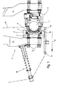
- FIG 1 this is a workpiece 1, e.g. one Crankshaft bearing, facing end of a tool 2 shown schematically, the two arms 3 and 4 of the Pliers 2 shown in Figure 1 in their closed position are.
- the processing arm 3 has at its free end a shoe 5 with two fastening screws 6 with the processing arm 3 is connected.
- the shoe 5 is on the screwed to the workpiece 1 facing side of the arm 3.
- the processing shoe 5 is on the workpiece 1 facing side with one essentially Partially circular recess 7 provided in one flexible processing shell 8 via two fastening elements 9 and 10 is included.
- the other processing arm 4 carries on its side facing the workpiece 1 a total designated 11 measuring device, which is not closer is designated and carried out with the in-process measurements can be. With this measuring device 11, e.g. during machining the diameter of the workpiece 1 and Surface ripples can be measured.
- the material removal from workpiece 1 takes place via a Sanding belt 12, which is between the two Machining arms 3 and 4 of the flexible machining shell 8 is fed and from the flexible processing tray 8 is pressed onto the surface of the workpiece 1.
- a Sanding belt 12 which is between the two Machining arms 3 and 4 of the flexible machining shell 8 is fed and from the flexible processing tray 8 is pressed onto the surface of the workpiece 1.
- the grinding belt 12 along the entire length of the Processing tray 8, i.e. over the whole of the Machining shell 8 covered circumferential angle on the workpiece 1 and is continuously or gradually in the lower Area subtracted.
- the grinding belt 12 over two Deflection rollers 13 deflected and in the direction of arrow 14 promoted.
- the removal is usually 5 ⁇ m to 8 ⁇ m, can also be 30 ⁇ m for in-process measurements.
- Out-of-roundness from 2 ⁇ m to 5 ⁇ m is corrected, i.e. worn away.
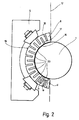
- FIG 2 is an enlarged view of the Flexible machining shell 8 abutting workpiece 1 shown. It can be clearly seen that the shell 8 Sanding belt 12 over its entire length to the surface of the Presses workpiece 1.
- the processing tray 8 supports this Sanding belt 12 with its first facing workpiece 1 Surface 16 off.
- the flexibility gets that Processing shell 8 through slots 17 and 18 with open edges, the slots 17 towards the first surface 16 and the Slits 18 to the opposite second surface 19 are open.
- the slots 17 and 18 extend here radially over about 80% of the total thickness d of the Machining tray 8.
- the depth a of the to the outer surface open slots 18 can be equal to the depth b of the slots 17th his; the two slots 17 and 18 can also have different depths a and b.
- the slots 17 and 18 are arranged on a gap, so that the Processing shell 8 a substantially meandering Shape or a lamella shape.
- the Machining tray 8 is in the direction of thickness d, i.e. in radial direction to the workpiece 1 relatively stiff, so that Sanding belt 12 snugly onto the surface of the workpiece 1 can be pressed on.
- the slots 17 and 18 the individual shell sections 20 of the Processing shell 8 a high flexibility or elasticity in a radial direction to one another, the shell sections 20 are rigid in the radial direction.
- the Shell sections 20 form individual U-shaped Section body, whose adjacent free leg are interconnected.
- FIG. 2a shows four preferred embodiments of the adaptive shell 8 shown.
- 29 and 30 there are slots referred to, which differ from the inner or -Extend the outer surface to approximately the middle of the shell.
- the slots 29 and 30 staggered, but they can also face each other.
- the second embodiment are only different from the outer surface of the shell 8 outgoing slots 18 and in the third embodiment slots 17 extending from the inner surface of the shell 8 available.
- the shown as the fourth embodiment Shell 8 is formed by two shell elements 8 'and 8 ", which are coaxial. There are corresponding ones Slots 18 and 17 radially one above the other.
- the illustrated Embodiments are intended to be exemplary only and not finally be understood.
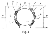
- two are each other opposing flexible processing trays 8 shown, but not as in the embodiment of Figure 1, are supported at points, but over almost their entire second surface 19 over one Support element 21 are supported.
- This support element 21 is inserted into the recess 7 of the shoe 5 and transmits the one acting in the direction of arrow 22 Press force evenly on the flexible processing shell 8.
- the support element 21 can e.g. made of steel, plastic, Rubber, felt, wood or the like. Alternatively is ensures that the contact pressure is transferred evenly becomes.
- Embodiment are either two sanding belts 12th used, or the same sanding belt is used after the first Pass redirected and again to the workpiece 1 introduced.
- 4 and 5 are conventional hard shells 26 shown. 4 shows in a greatly exaggerated manner Way the location of the shoe 26 at the beginning of Editing process.
- the free press mainly Ends 27 of the hard shell 26, the grinding belt 12 on the Surface of the workpiece 1, whereas the middle Area 28 is hardly involved in material removal. It is easy to see that the hard shell 26 has a ripple of the workpiece 1 follows, since it only has the free ends 27 rests on the workpiece surface. A form correction can not or only at this stage marginally achieved.
Landscapes
- Engineering & Computer Science (AREA)
- Mechanical Engineering (AREA)
- Finish Polishing, Edge Sharpening, And Grinding By Specific Grinding Devices (AREA)
- Grinding Of Cylindrical And Plane Surfaces (AREA)
Description
- Figur 1
- eine Prinzipskizze einer flexiblen Bearbeitungsschale an einer Bandfinishmaschine;
- Figur 2
- eine vergrößerte Darstellung der Bearbeitungsschale der Figur 1;
- Figur 2a
- weitere Ausführungsformen der Bearbeitungsschale;
- Figur 3
- eine schematische Darstellung einer anderen Ausführungsform der Erfindung; und
- Figuren 4 und 5
- eine starre Bearbeitungsschale gemäß dem Stand der Technik.
Claims (17)
- Feinstbearbeitungsmaschine zum Bearbeiten von zylindrischen Innen- oder Außenflächen eines Werkstücks (1) mit wenigstens einem an der Innen- oder Außenfläche des Werkstücks (1) anliegenden Finishelement, mit einem Spannmittel um das Finishelement gegen die zu bearbeitende Oberfläche zu pressen, mit Mitteln zum Erzeugen einer Relativbewegung zwischen dem Werkstück (1) und dem Finishelement, wobei das Finishelement wenigstens eine die zu bearbeitende Oberfläche teilweise umgreifende, C-förmige Schale (8) aufweist, und die Schale (8) derart flexibel ist, daß sie sich radial an die zu bearbeitende Oberfläche kreisgeometrisch anpassen kann, dadurch gekennzeichnet, daß die dem zu bearbeitenden Werkstück (1) zugewandte Oberfläche (16) und/oder abgewandte Oberfläche (19) der Schale (8) mit mindestens einer parallel zur Drehachse verlaufenden randoffenen Ausnehmung versehen ist und die Schale (8) im Querschnitt eine im wesentlichen lamellenförmige Gestalt aufweist, wobei die Lamellenspitzen auf dem Werkstück aufliegen und/oder vom Werkstück (1) weg gerichtet sind.
- Feinstbearbeitungsmaschine nach Anspruch 1, dadurch gekennzeichnet, daß die Ausnehmung ein Schlitz (17 oder 18) ist.
- Feinstbearbeitungsmaschine nach Anspruch 1 oder 2, dadurch gekennzeichnet, daß die Ausnehmungen auf Lücke versetzt oder gegenüber angeordnet sind.
- Feinstbearbeitungsmaschine nach einem der vorhergehenden Ansprüche, dadurch gekennzeichnet, daß die Ausnehmungen einen im wesentlichen trapezförmigen, ausgerundeten oder rechteckförmigen Querschnitt aufweisen.
- Feinstbearbeitungsmaschine nach einem der vorhergehenden Ansprüche, dadurch gekennzeichnet, daß die Tiefe der Ausnehmungen mindestens 10% der Dicke der Schale (8) ist.
- Feinstbearbeitungsmaschine nach einem der vorhergehenden Ansprüche, dadurch gekennzeichnet, daß die Schale (8) ein Anpreßelement für ein mit Schleifmittel beschichtetes, insbesondere dünnes Schleifband (12) ist.
- Feinstbearbeitungsmaschine nach einem der Ansprüche 1 bis 5, dadurch gekennzeichnet, daß die Schale (8) an ihrer am Werkstück (1) anliegenden Oberfläche (16) mit Schleifmittel, insb. Edelkorund, SiCa, CBN, Diamant usw. beschichtet bzw. bestückt ist.
- Feinstbearbeitungsmaschine nach einem der Ansprüche 1 bis 5, dadurch gekennzeichnet, daß die Schale (8) gebundenes Schleifmittel enthält und insbesondere ein Schleifstein ist.
- Feinstbearbeitungsmaschine nach Anspruch 1, dadurch gekennzeichnet, daß die Schale (8) von einem Dehnspannschuh (23) gestützt wird.
- Feinstbearbeitungsmaschine nach Anspruch 9, dadurch gekennzeichnet, daß der Dehnspannschuh mit einem parallel bzw. koaxial zur Anlagefläche sich erstreckenden Hohlraum (24) für ein Druckmedium versehen ist.
- Feinstbearbeitungsmaschine nach Anspruch 9 oder 10, dadurch gekennzeichnet, daß der Dehnspannschuh (23) aus einem flexiblen, fluiddichten Material hergestellt ist.
- Feinstbearbeitungsmaschine nach einem der vorhergehenden Ansprüche, dadurch gekennzeichnet, daß die Schale (8) aus Metall, wie Stahl oder Buntmetall, oder aus Kunststoff, Keramik, Gummi, Holz o.dgl., hergestellt ist.
- Feinstbearbeitungsmaschine nach einem der vorhergehenden Ansprüche, dadurch gekennzeichnet, daß die Schale (8) an ihrer Rückseite vollflächig oder punktweise abgestützt ist.
- Adaptives Finishelement für eine Feinstbearbeitungsmaschine nach einem der vorhergehenden Ansprüche, wobei das Finishelement wenigstens eine die zu bearbeitende Oberfläche teilweise umgreifende, C-förmige Schale (8) aufweist, und die Schale (8) derart flexibel ist, daß sie sich radial an die zu bearbeitende Oberfläche kreisgeometrisch anpassen kann, dadurch gekennzeichnet, daß die dem zu bearbeitenden Werkstück (1) zugewandte Oberfläche (16) und/oder abgewandte Oberfläche (19) der Schale (8) mit mindestens einer parallel zur Drehachse verlaufenden randoffenen Ausnehmung versehen ist und die Schale (8) im Querschnitt eine im wesentlichen lamellenförmige Gestalt aufweist, wobei die Lamellenspitzen auf dem Werkstück aufliegen und/oder vom Werkstück (1) weg gerichtet sind.
- Adaptives Finishelement nach einem der Ansprüche 14, dadurch gekennzeichnet, daß die Schale (8) ein- oder mehrteilig ist.
- Verwendung eines adaptiven Finishelements nach Anspruch 14 oder 15 zusammen mit einem dünnen und/oder inkompressiblen, insbesondere aus Kunststoff bestehendem Schleifband.
- Verwendung eines adaptives Finishelement nach Anspruch 14 oder 15 als Finishstein.
Priority Applications (2)
| Application Number | Priority Date | Filing Date | Title |
|---|---|---|---|
| DE59508072T DE59508072D1 (de) | 1995-12-28 | 1995-12-28 | Feinstbearbeitungsmaschine |
| EP19950120683 EP0781627B1 (de) | 1995-12-28 | 1995-12-28 | Feinstbearbeitungsmaschine |
Applications Claiming Priority (1)
| Application Number | Priority Date | Filing Date | Title |
|---|---|---|---|
| EP19950120683 EP0781627B1 (de) | 1995-12-28 | 1995-12-28 | Feinstbearbeitungsmaschine |
Publications (2)
| Publication Number | Publication Date |
|---|---|
| EP0781627A1 EP0781627A1 (de) | 1997-07-02 |
| EP0781627B1 true EP0781627B1 (de) | 2000-03-22 |
Family
ID=8219933
Family Applications (1)
| Application Number | Title | Priority Date | Filing Date |
|---|---|---|---|
| EP19950120683 Expired - Lifetime EP0781627B1 (de) | 1995-12-28 | 1995-12-28 | Feinstbearbeitungsmaschine |
Country Status (2)
| Country | Link |
|---|---|
| EP (1) | EP0781627B1 (de) |
| DE (1) | DE59508072D1 (de) |
Cited By (2)
| Publication number | Priority date | Publication date | Assignee | Title |
|---|---|---|---|---|
| DE102007051047A1 (de) | 2007-10-16 | 2009-04-23 | Nagel Maschinen- Und Werkzeugfabrik Gmbh | Andrückeinrichtung für Schneidmittel sowie Vorrichtung und Verfahren zur Finishbearbeitung von Umfangsflächen an zylindrischen Werkstückabschnitten |
| EP2327510A1 (de) * | 2009-11-25 | 2011-06-01 | Supfina Grieshaber GmbH & Co. KG | Finishvorrichtung |
Families Citing this family (3)
| Publication number | Priority date | Publication date | Assignee | Title |
|---|---|---|---|---|
| DE10332605B4 (de) * | 2003-07-17 | 2005-09-15 | Ibz Gmbh | Anpressvorrichtung für eine Oberflächenbearbeitungsvorrichtung |
| DE50301626D1 (de) * | 2003-08-15 | 2005-12-15 | Supfina Grieshaber Gmbh & Co | Werkzeug zur Feinstbearbeitung |
| CN116587148B (zh) * | 2023-07-17 | 2023-10-03 | 智龙直线(瑞金)科技有限公司 | 一种用于滑座球沟的抛光装置及其抛光方法 |
Family Cites Families (3)
| Publication number | Priority date | Publication date | Assignee | Title |
|---|---|---|---|---|
| FR2079743A5 (de) * | 1970-02-11 | 1971-11-12 | Spidem Ste Nle | |
| CA1265343A (en) * | 1984-05-07 | 1990-02-06 | Edward Earl Judge Jr. | Microfinishing apparatus and method |
| DE3813484A1 (de) * | 1988-04-21 | 1989-11-02 | Ford Werke Ag | Vorrichtung zur feinbearbeitung der hubzapfen von kurbelwellen |
-
1995
- 1995-12-28 DE DE59508072T patent/DE59508072D1/de not_active Expired - Lifetime
- 1995-12-28 EP EP19950120683 patent/EP0781627B1/de not_active Expired - Lifetime
Cited By (5)
| Publication number | Priority date | Publication date | Assignee | Title |
|---|---|---|---|---|
| DE102007051047A1 (de) | 2007-10-16 | 2009-04-23 | Nagel Maschinen- Und Werkzeugfabrik Gmbh | Andrückeinrichtung für Schneidmittel sowie Vorrichtung und Verfahren zur Finishbearbeitung von Umfangsflächen an zylindrischen Werkstückabschnitten |
| DE202008018526U1 (de) | 2007-10-16 | 2015-02-25 | Nagel Maschinen- Und Werkzeugfabrik Gmbh | Andrückeinrichtungfür Schmittel sowie Vorrichtung zur Finishbearbeitung von Umfangsflächen an zylindrischen Werkstückabschnitten |
| DE202008018607U1 (de) | 2007-10-16 | 2016-07-29 | Nagel Maschinen- Und Werkzeugfabrik Gmbh | Andrückeinrichtung für Schneidmittel sowie Vorrichtung zur Finishbearbeitung von Umfangsflächen an zylindrischen Werkstückabschnitten |
| DE102007051047B4 (de) | 2007-10-16 | 2023-03-23 | Nagel Maschinen- Und Werkzeugfabrik Gmbh | Andrückeinrichtung für Finishband sowie Vorrichtung und Verfahren zur Finishbearbeitung von Umfangsflächen an zylindrischen Werkstückabschnitten |
| EP2327510A1 (de) * | 2009-11-25 | 2011-06-01 | Supfina Grieshaber GmbH & Co. KG | Finishvorrichtung |
Also Published As
| Publication number | Publication date |
|---|---|
| EP0781627A1 (de) | 1997-07-02 |
| DE59508072D1 (de) | 2000-04-27 |
Similar Documents
| Publication | Publication Date | Title |
|---|---|---|
| DE60030790T2 (de) | Verfahren zum Schleifen eines Werkstücks mit welchem konstante Zeitspaltvolumen erzielt werden | |
| DE10144649C5 (de) | Verfahren zur drallfreien spanenden Bearbeitung von rotationssymmetrischen Flächen | |
| DE3686801T3 (de) | Feinstbearbeitungsvorrichtung und Verfahren. | |
| EP1525073B1 (de) | Verfahren und vorrichtung zum schleifen eines rotationssymmetrischen maschinenbauteils | |
| DE10235808A1 (de) | Verfahren und Vorrichtung zum Schleifen eines mit einer Längsbohrung versehenen rotationssymmetrischen Maschinenbauteils | |
| EP1533078B1 (de) | Geteiltes Schleifwerkzeug | |
| DE202008018607U1 (de) | Andrückeinrichtung für Schneidmittel sowie Vorrichtung zur Finishbearbeitung von Umfangsflächen an zylindrischen Werkstückabschnitten | |
| DE102004022360B4 (de) | Verfahren zur Feinbearbeitung, vorzugsweise zur Feinstschlichtbearbeitung, von Werkstücken vorzugsweise von Kurbelwellen | |
| DE4444239C2 (de) | Feinstbearbeitungsmaschine | |
| DE2714222A1 (de) | Verfahren und vorrichtung zur feinbearbeitung der anlaufbunde fuer waelzkoerper von waelzlagern | |
| EP0503491A1 (de) | Werkzeugmaschine zur spanabhebenden Bearbeitung | |
| DE10208423A1 (de) | Schleifscheibe mit Abtragungssegmentplatten mit zumindest zwei Abtragungssegmentplatten, deren Umfangslängen von einander verschieden sind | |
| DE833605C (de) | Honwerkzeug | |
| DE102006014972B4 (de) | Kombiniertes Bearbeitungsverfahren und Bearbeitungseinrichtung | |
| EP0997229B1 (de) | Verfahren und Vorrichtung zur Feinbearbeitung von im wesentlichen zylindrischen Werkstückoberflächen | |
| EP0781627A1 (de) | Feinstbearbeitungsmaschine | |
| DE19607778C2 (de) | Vorrichtung zur Finish-Bearbeitung, insbesondere von Kurbel- oder Nockenwellen | |
| DE602004006149T3 (de) | Schleifgerät, dessen Anwendung zum Schleifen von zylindrischen Gegenständen , Vorrichtung und Verfahren zum Schleifen von zylindrischen Gegenständen | |
| DE2614843C2 (de) | Kopierschleifmaschine | |
| DE10342137B4 (de) | Vorrichtung und Verfahren zur Finishbearbeitung von Wellen, insbesondere von Kurbel- und Nockenwellen | |
| DE19607776A1 (de) | Verfahren und Vorrichtung zur Finish-Bearbeitung, insbesondere von Kurbel- oder Nockenwellen | |
| DE29819443U1 (de) | Vorrichtung zur Feinbearbeitung von im wesentlichen zylindrischen Werkstückoberflächen | |
| DE102021201070A1 (de) | Honleiste, Verfahren zur Herstellung einer Honleiste sowie Honwerkzeug | |
| DD297357A5 (de) | Verfahren und einrichtung zum abrichten von zylindrischen ein- und mehrgaengigen schleifschnecken | |
| DE19607821A1 (de) | Vorrichtung zur Finish-Bearbeitung, insbesondere von Kurbel- oder Nockenwellen |
Legal Events
| Date | Code | Title | Description |
|---|---|---|---|
| PUAI | Public reference made under article 153(3) epc to a published international application that has entered the european phase |
Free format text: ORIGINAL CODE: 0009012 |
|
| 17P | Request for examination filed |
Effective date: 19960814 |
|
| AK | Designated contracting states |
Kind code of ref document: A1 Designated state(s): DE FR GB |
|
| AX | Request for extension of the european patent |
Free format text: LT;LV;SI |
|
| 17Q | First examination report despatched |
Effective date: 19980827 |
|
| GRAG | Despatch of communication of intention to grant |
Free format text: ORIGINAL CODE: EPIDOS AGRA |
|
| GRAG | Despatch of communication of intention to grant |
Free format text: ORIGINAL CODE: EPIDOS AGRA |
|
| GRAH | Despatch of communication of intention to grant a patent |
Free format text: ORIGINAL CODE: EPIDOS IGRA |
|
| GRAH | Despatch of communication of intention to grant a patent |
Free format text: ORIGINAL CODE: EPIDOS IGRA |
|
| GRAA | (expected) grant |
Free format text: ORIGINAL CODE: 0009210 |
|
| DAX | Request for extension of the european patent (deleted) | ||
| RBV | Designated contracting states (corrected) |
Designated state(s): DE FR GB |
|
| RIN1 | Information on inventor provided before grant (corrected) |
Inventor name: STEINWENDER, HORST |
|
| AK | Designated contracting states |
Kind code of ref document: B1 Designated state(s): DE FR GB |
|
| GBT | Gb: translation of ep patent filed (gb section 77(6)(a)/1977) |
Effective date: 20000324 |
|
| REF | Corresponds to: |
Ref document number: 59508072 Country of ref document: DE Date of ref document: 20000427 |
|
| ET | Fr: translation filed | ||
| PLBE | No opposition filed within time limit |
Free format text: ORIGINAL CODE: 0009261 |
|
| STAA | Information on the status of an ep patent application or granted ep patent |
Free format text: STATUS: NO OPPOSITION FILED WITHIN TIME LIMIT |
|
| 26N | No opposition filed | ||
| REG | Reference to a national code |
Ref country code: FR Ref legal event code: CD Ref country code: FR Ref legal event code: CA |
|
| REG | Reference to a national code |
Ref country code: FR Ref legal event code: RM |
|
| REG | Reference to a national code |
Ref country code: GB Ref legal event code: IF02 |
|
| PGFP | Annual fee paid to national office [announced via postgrant information from national office to epo] |
Ref country code: FR Payment date: 20110107 Year of fee payment: 16 |
|
| PGFP | Annual fee paid to national office [announced via postgrant information from national office to epo] |
Ref country code: GB Payment date: 20101117 Year of fee payment: 16 |
|
| PGFP | Annual fee paid to national office [announced via postgrant information from national office to epo] |
Ref country code: DE Payment date: 20110222 Year of fee payment: 16 |
|
| GBPC | Gb: european patent ceased through non-payment of renewal fee |
Effective date: 20111228 |
|
| REG | Reference to a national code |
Ref country code: FR Ref legal event code: ST Effective date: 20120831 |
|
| REG | Reference to a national code |
Ref country code: DE Ref legal event code: R119 Ref document number: 59508072 Country of ref document: DE Effective date: 20120703 |
|
| PG25 | Lapsed in a contracting state [announced via postgrant information from national office to epo] |
Ref country code: GB Free format text: LAPSE BECAUSE OF NON-PAYMENT OF DUE FEES Effective date: 20111228 Ref country code: DE Free format text: LAPSE BECAUSE OF NON-PAYMENT OF DUE FEES Effective date: 20120703 |
|
| PG25 | Lapsed in a contracting state [announced via postgrant information from national office to epo] |
Ref country code: FR Free format text: LAPSE BECAUSE OF NON-PAYMENT OF DUE FEES Effective date: 20120102 |