EP0784218A1 - Optical fiber connector plug and optical fiber connector - Google Patents
Optical fiber connector plug and optical fiber connector Download PDFInfo
- Publication number
- EP0784218A1 EP0784218A1 EP96923054A EP96923054A EP0784218A1 EP 0784218 A1 EP0784218 A1 EP 0784218A1 EP 96923054 A EP96923054 A EP 96923054A EP 96923054 A EP96923054 A EP 96923054A EP 0784218 A1 EP0784218 A1 EP 0784218A1
- Authority
- EP
- European Patent Office
- Prior art keywords
- optical fiber
- ferrule
- optical connector
- tension
- housing
- Prior art date
- Legal status (The legal status is an assumption and is not a legal conclusion. Google has not performed a legal analysis and makes no representation as to the accuracy of the status listed.)
- Ceased
Links
Images



Classifications
-
- G—PHYSICS
- G02—OPTICS
- G02B—OPTICAL ELEMENTS, SYSTEMS OR APPARATUS
- G02B6/00—Light guides; Structural details of arrangements comprising light guides and other optical elements, e.g. couplings
- G02B6/24—Coupling light guides
- G02B6/36—Mechanical coupling means
- G02B6/38—Mechanical coupling means having fibre to fibre mating means
- G02B6/3807—Dismountable connectors, i.e. comprising plugs
- G02B6/381—Dismountable connectors, i.e. comprising plugs of the ferrule type, e.g. fibre ends embedded in ferrules, connecting a pair of fibres
- G02B6/3825—Dismountable connectors, i.e. comprising plugs of the ferrule type, e.g. fibre ends embedded in ferrules, connecting a pair of fibres with an intermediate part, e.g. adapter, receptacle, linking two plugs
-
- G—PHYSICS
- G02—OPTICS
- G02B—OPTICAL ELEMENTS, SYSTEMS OR APPARATUS
- G02B6/00—Light guides; Structural details of arrangements comprising light guides and other optical elements, e.g. couplings
- G02B6/24—Coupling light guides
- G02B6/36—Mechanical coupling means
- G02B6/38—Mechanical coupling means having fibre to fibre mating means
- G02B6/3807—Dismountable connectors, i.e. comprising plugs
- G02B6/3869—Mounting ferrules to connector body, i.e. plugs
-
- G—PHYSICS
- G02—OPTICS
- G02B—OPTICAL ELEMENTS, SYSTEMS OR APPARATUS
- G02B6/00—Light guides; Structural details of arrangements comprising light guides and other optical elements, e.g. couplings
- G02B6/24—Coupling light guides
- G02B6/36—Mechanical coupling means
- G02B6/38—Mechanical coupling means having fibre to fibre mating means
- G02B6/3807—Dismountable connectors, i.e. comprising plugs
- G02B6/3873—Connectors using guide surfaces for aligning ferrule ends, e.g. tubes, sleeves, V-grooves, rods, pins, balls
- G02B6/3874—Connectors using guide surfaces for aligning ferrule ends, e.g. tubes, sleeves, V-grooves, rods, pins, balls using tubes, sleeves to align ferrules
-
- G—PHYSICS
- G02—OPTICS
- G02B—OPTICAL ELEMENTS, SYSTEMS OR APPARATUS
- G02B6/00—Light guides; Structural details of arrangements comprising light guides and other optical elements, e.g. couplings
- G02B6/24—Coupling light guides
- G02B6/36—Mechanical coupling means
- G02B6/38—Mechanical coupling means having fibre to fibre mating means
- G02B6/3807—Dismountable connectors, i.e. comprising plugs
- G02B6/3887—Anchoring optical cables to connector housings, e.g. strain relief features
- G02B6/3888—Protection from over-extension or over-compression
-
- G—PHYSICS
- G02—OPTICS
- G02B—OPTICAL ELEMENTS, SYSTEMS OR APPARATUS
- G02B6/00—Light guides; Structural details of arrangements comprising light guides and other optical elements, e.g. couplings
- G02B6/24—Coupling light guides
- G02B6/36—Mechanical coupling means
- G02B6/38—Mechanical coupling means having fibre to fibre mating means
- G02B6/3807—Dismountable connectors, i.e. comprising plugs
- G02B6/381—Dismountable connectors, i.e. comprising plugs of the ferrule type, e.g. fibre ends embedded in ferrules, connecting a pair of fibres
- G02B6/3818—Dismountable connectors, i.e. comprising plugs of the ferrule type, e.g. fibre ends embedded in ferrules, connecting a pair of fibres of a low-reflection-loss type
- G02B6/3821—Dismountable connectors, i.e. comprising plugs of the ferrule type, e.g. fibre ends embedded in ferrules, connecting a pair of fibres of a low-reflection-loss type with axial spring biasing or loading means
-
- G—PHYSICS
- G02—OPTICS
- G02B—OPTICAL ELEMENTS, SYSTEMS OR APPARATUS
- G02B6/00—Light guides; Structural details of arrangements comprising light guides and other optical elements, e.g. couplings
- G02B6/24—Coupling light guides
- G02B6/36—Mechanical coupling means
- G02B6/38—Mechanical coupling means having fibre to fibre mating means
- G02B6/3807—Dismountable connectors, i.e. comprising plugs
- G02B6/3833—Details of mounting fibres in ferrules; Assembly methods; Manufacture
- G02B6/3855—Details of mounting fibres in ferrules; Assembly methods; Manufacture characterised by the method of anchoring or fixing the fibre within the ferrule
-
- G—PHYSICS
- G02—OPTICS
- G02B—OPTICAL ELEMENTS, SYSTEMS OR APPARATUS
- G02B6/00—Light guides; Structural details of arrangements comprising light guides and other optical elements, e.g. couplings
- G02B6/24—Coupling light guides
- G02B6/36—Mechanical coupling means
- G02B6/38—Mechanical coupling means having fibre to fibre mating means
- G02B6/3807—Dismountable connectors, i.e. comprising plugs
- G02B6/3873—Connectors using guide surfaces for aligning ferrule ends, e.g. tubes, sleeves, V-grooves, rods, pins, balls
- G02B6/3874—Connectors using guide surfaces for aligning ferrule ends, e.g. tubes, sleeves, V-grooves, rods, pins, balls using tubes, sleeves to align ferrules
- G02B6/3877—Split sleeves
-
- G—PHYSICS
- G02—OPTICS
- G02B—OPTICAL ELEMENTS, SYSTEMS OR APPARATUS
- G02B6/00—Light guides; Structural details of arrangements comprising light guides and other optical elements, e.g. couplings
- G02B6/24—Coupling light guides
- G02B6/36—Mechanical coupling means
- G02B6/38—Mechanical coupling means having fibre to fibre mating means
- G02B6/3807—Dismountable connectors, i.e. comprising plugs
- G02B6/389—Dismountable connectors, i.e. comprising plugs characterised by the method of fastening connecting plugs and sockets, e.g. screw- or nut-lock, snap-in, bayonet type
- G02B6/3893—Push-pull type, e.g. snap-in, push-on
Definitions
- the present invention relates to an optical connector for connecting optical fibers, and more particularly to a plug-adapter-plug type optical connector for connecting plugs through an adapter and also to an optical connector plug thereof.
- FC connector of JIS C 5970 F01 type an SC connector of JIS C 5973 F01
- MPO connector disclosed in Japanese Utility Model Publication No. 4-49606 and Japanese Patent Application laid-Open No. 4-347806.
- optical connectors are assumed to be connected and disconnected frequently, they are required to have a function to position an optical fiber with high precision and a function to maintain the close junction between optical fibers.
- a ferrule in a housing of each connector plug is made axially movable and is biassed from the rear by a coil spring. When the connector plugs are coupled, the ferrule is moved rearwardly against a biassing force to produce a predetermined pressing force.
- the optical fiber cord used on this connector is a so-called tension-resistant fiber-covered optical fiber cord, which, as shown in Fig.
- a secondary coated optical fiber made up of a primary coated optical fiber (a bare optical fiber) covered with an optical fiber jacket of resin; a tension-resistant fiber enclosing the secondary coated optical fiber; and an optical cord jacket enclosing all these.
- the end of the tension-resistant fiber is secured to the housing to prevent the secondary coated optical fiber from being tensed.
- a tension-resistant jacket-covered optical fiber cord in which, as shown in Fig. 2, an optical cord jacket is directly fitted substantially tightly over the secondary coated optical fiber and is provided with a tension resisting capability.
- a primary object of this invention is to solve the aforementioned problems experienced with the prior art and to provide an optical connector plug and an optical connector that can stably couple even a tension-resistant jacket-covered optical fiber cord.
- an optical connector plug comprising:
- the housing may comprise a plug frame, a stop sleeve and an elastic hood.
- the tension-resistant jacket of the optical fiber cord may be bonded to a rear end portion of the elastic hood of the housing.
- the housing may be integrally formed with an adapter to which a mating optical connector plug to be connected are inserted.
- an optical connector comprising:
- the connecting adapter may comprise means for axially biassing the pair of optical connector plugs so as to connect to each other.
- an optical connector plug comprising:
- a refraction index matching agent may be coated on a connecting surface of the optical connector plugs to be mutually connected.
- an optical fiber cord has a construction wherein at least a jacket carries tension, a secondary coated optical fiber of the optical fiber cord and the jacket carrying the tension are secured to the ferrule, and the ferrule is immovably mounted to the housing.
- Fig. 1 shows an embodiment of an optical connector plug 10 according to the invention which comprises a ferrule 14 and a housing 16 which houses and holds the ferrule.
- a tension-resistant jacket-covered optical fiber cord which includes: a secondary coated optical fiber 120 consisting of a primary-coated (bare) optical fiber 121 covered with an optical fiber jacket 122 of resin; and an optical cord jacket 123 directly fitted substantially tightly over the secondary coated optical fiber 120 and provided with a capability to carry tension.
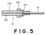
- the end of the optical fiber cord 12 is secured to the ferrule 14 such that the secondary coated optical fiber 120 stripped of the optical cord jacket 123 is exposed at the front end surface of the ferrule 14, as particularly shown in Fig. 5.
- the jacket 123 is also adhesively fixed to the rear end of the ferrule 14.
- the ferrule 14 has an elongated cylindrical body 140 and a cap member 141, fitted to the body 140, forming a disk-shaped flange 1411 at the middle of the ferrule 14.
- a positioning notch 1412 is formed on the disk-shaped flange 1411 (see Fig. 1).
- the optical cord jacket 123 is stripped at its distal end, however it should be appreciated that the optical fiber cord 12 can be exposed at the front end surface of the ferrule 14 without the optical cord jacket 123 being striped.
- the disc-like flange 1411 is not necessary to be cylindrical and may be non-cylindrical.
- the housing 16 in this embodiment comprises a plug frame 161, a stop sleeve 162, and a resilient hood, for example, a rubber hood 163.
- the plug frame 161 has a guide cylinder portion 1611 at the front end, an annular locking notch 1612 for engagement with the adapter etc. on the outer circumference, a stepped portion 1613 on the inner circumference to receive the disk-shaped flange 1411 of the ferrule 14, and a guide cylinder portion 1614 at the rear end.
- the rear guide cylinder portion 1614 has locking holes 1615 180 degrees apart.
- the stop sleeve 162 comprises a guide cylinder portion 1621 fitted into the rear guide cylinder portion 1614 of the plug frame 161, projections 1622 formed on the outer circumference and engaged in the locking holes 1615, a stepped portion 1623 formed on the inner circumference, and a restriction cylinder 1624 at the rear end.
- Denoted 18 is a cylindrical spacer which is disposed between the stepped portion 1623 of the stop sleeve 162 and the flange 1411 of the ferrule 14 so as to immovably fix the ferrule 14 in the housing 16.
- the stop sleeve 162 and the spacer 18 may be integrally molded.
- the ferrule 14 to which the optical fiber cord 12 is secured is inserted into the plug frame 161, with the flange 1411 of the ferrule 14 being positioned by the notch 1412 and seated on the stepped portion 1613. Then, the stop sleeve 162, together with the spacer 18, is inserted into the plug frame 161 to fit its guide cylinder portion 1621 into the rear guide cylinder portion 1614 of the plug frame 161 until the projections 1622 engage in the locking holes 1615.
- the front end of the rubber hood 163 is adhesively bonded to the rear end of the plug frame 161.
- the optical fiber cord 12 extends outside through an insertion hole 1631 in the rubber hood 163.
- the ferrule 14 having the optical fiber cord 12 fixed thereto is secured to the housing 16 so that it cannot be moved in the direction of the optical axis of the fiber.
- the optical fiber cord 12 is directly fixed to the housing 16 Further, any effects to connected portions caused by torsion of the optical fiber cord 12 can be eliminated by adhesively bonding the optical fiber cord 12 to the rubber hood 163 in the insertion hole 1631.
- optical connector plug 10 of this invention used in combination with an adapter 20 of Fig. 3, constitutes an optical connector.
- the mating optical connector plug 10' be of a type that, when pushed, allows the ferrule 14' to be moved axially.
- the optical fiber cord 22 used in the optical connector plug 10' is a so-called tension-resistant fiber-covered optical fiber cord, which, as shown in Fig. 4, comprises: a secondary coated optical fiber 220 made up of a primary coated optical fiber 221 and an optical fiber jacket 222 of resin covering the primary coated optical fiber 221; a tension-resistant fiber 223 enclosing the secondary coated optical fiber 220; and an optical cord jacket 224 enclosing these.
- the secondary coated optical fiber 220 of the optical fiber cord 22 is secured at one end to the ferrule 14', with the secondary coated optical fiber 220 stripped of the optical cord jacket 224 and tension-resistant fiber 223 and exposed at the front end surface of the ferrule 14'.
- the tension-resistant fiber 223 is caulked and secured to a restriction cylinder 1624' of a stop sleeve 162' by a first retainer tube 24 and the optical cord jacket 224 is caulked and secured to the rear small-diameter portion of the first retainer tube 24 by a second retainer tube 26, resulting in both being secured to the housing 16'.
- the ferrule 14' has a cylindrical body 140' and a cap member 141' as well as a cylindrical or non-cylindrical disk-shaped flange 1411' as set forth above at the intermediate portion, which has a positioning notch 1412'.
- a housing 16' comprises a plug frame 161', a stop sleeve 162' and a rubber hood 163'.
- the plug frame 161' has a guide cylinder portion 1611' at the front end, an annular locking notch 1612' on the outer circumference, a stepped portion 1613' on the inner circumference to accommodate and hold the disk-shaped flange 1411' of the ferrule 14', and a guide cylinder portion 1614' at the rear end.
- the guide cylinder portion 1614' is formed with locking holes 1615' 180 degrees apart from each other.
- the stop sleeve 162' comprises a guide cylinder portion 1621' fitted into the rear guide cylinder portion 1614' of the plug frame 161', projections 1622' formed on the outer circumference and engaged in the locking holes 1615', a stepped portion 1623' formed on the inner circumference, and a restriction cylinder 1624' at the rear end.
- Designated 28 is a coil spring, which is disposed between the flange 1411' of the ferrule 14' and the stepped portion 1623' of the stop sleeve 162'.
- the ferrule 14' is movably biassed by this spring 28 so as to allow the flange 1411' to abut against the stepped portion 1613' of the plug frame 161'.
- the front end of the rubber hood 163' is adhesively bonded to the rear end of the plug frame 161'.
- the ferrule 14' having the secondary coated optical fiber 220 fixed thereto is movably mounted in the housing 16', with the end of the tension-resistant fiber 223 secured to the housing 16' so that tension is not applied to the secondary coated optical fiber 220.
- Optical connection is made by inserting such optical connector plugs 10 and 10' from opposite sides of the connecting adapter 20.
- the connecting adapter 20 is formed, for example as shown in Fig. 3, symmetrical with respect to the center plane C and accommodates a sleeve holder 206 inside a cylindrical housing 204 formed with a support portion 202 which serves as a mount portion on a panel and the like or a knob.
- the sleeve holder 206 has a pair of left and right radially resilient locking claws 208 formed integral therewith and holds a cylindrical elastic sleeve 210 concentric with the cylindrical housing 204.
- the front end of the ferrule 14 is inserted into the elastic sleeve 210 with the guide cylinder portion 1611 guided along the outer circumference of the elastic sleeve 210 until the locking claws 208 engage with the annular locking notch 1612, at which time the optical connector plug 10 is held in position.
- the dimensions of these members are so set that, with the optical connector plug 10 held in place, the front end surface of the ferrule 14 is flush with the center plane C of the adapter 20.
- the front end of the ferrule 14' is inserted into the elastic sleeve 210 with the guide cylinder portion 1611' guided along the outer circumference of the elastic sleeve 210 until the locking claws 208 engage with the annular locking notch 1612'.
- the optical connector plug 10' is held in position.
- the front end surface of the ferrule 14' comes in contact with the front end surface of the ferrule 14 and then deflects the spring 28.
- the biassing force of the spring 28 of the optical connector plug 10' gives a closely connected condition between ferrules 14 and 14' and prevents connection losses in optical connection from increasing.
- the connecting adapter 20 may be formed integral with either of the plug frames 161 and 161', which makes up a part of the housing 16 or 16' of the optical connector plug 10 or 10'.
- the mating optical connector plug is inserted into the adapter 20 thus formed integral with the optical connector plug.
- to form integral means to include both “to form the plug frame and the adapter by integrally molding them” and “to form the plug frame and the adapter separately and then integrate them by bonding". This simplifies the coupling procedure.
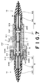
- FIG. 7 Another embodiment of the connecting adapter will be discussed referring to Fig. 7.
- the members whose constructions are identical with those of the connecting adapter 20 set forth above are assigned like reference numerals but with a prime "'" to simplify the discussion.
- the connecting adapter 20' shown in Fig. 7 is constructed such that a biassing force can be applied axially in either of directions to ensure the mutual connection of the optical connector plugs to be connected.
- the connecting adapter 20' in this embodiment comprises an enlarged sleeve 212 which is radially enlarged to define a cylindrical space 214 inside a portion on the left side with respect to the center plane C in Fig. 7 in comparison with the sleeve holder 206 set force above.
- locking claws 2080 which are connected to each other by a flange 2081 are axially movably provided within the cylindrical space 214.
- the locking claws 2080 are axially biassed by a spring 216 at the flange 2081 in the right direction as illustrated.
- the connecting adapter 20' as constructed above, when the optical connector plug 10 is inserted from one end, on the left side, of the adapter, the front end of the ferrule 14 is inserted into the elastic sleeve 210' with the guide cylinder 1611 guided along the outer circumference of the elastic sleeve 210, and then the locking claws 2080 engage with the locking notch 1612, resulting in the optical connector plug 10 is held in a first predetermined position where the front surface of the ferrule 14 slightly projects from the center plane C of the connecting adapter 20'.
- the front end of the ferrule 14 is inserted into the elastic sleeve 210' with the guide cylinder 1611 guided along the outer circumference of the elastic sleeve 210', and then the locking claws 208' engage the locking notch 1612, resulting in the optical connector plug 10 is held in a second predetermined position.
- Denoted 230 is a split sleeve, which is optionally provided within the elastic sleeve 210', made of, for example, phosphor bronze or zirconia.
- the split sleeve 230 is used to enhance radial precession of the ferrules to be coupled.
- An optical connector plug 10'' according to this embodiment is intended to simplify its structure and to reduce costs by omitting the plug frame and the stop sleeve from the housing of the above mentioned embodiments. As a result, only a portion of a ferrule is accommodated within a housing.
- a ferrule 14'' of the optical connector plug 10'' according to this embodiment in which the ferrule is immovable comprises an elongated cylindrical body 140'' and a cap member 141'', which is fitted to the body 140'', forming a first flange 1411'' with a large diameter at the middle portion of the ferrule 14'' and a second flange 1413'' with a small diameter at the rear portion of the ferrule 14''.
- a relationship in connection between the ferrule body 140'' and both the secondary coated optical fiber 120 and the optical cord jacket 123 of the optical fiber cord 12 is the same as that of the previous embodiment which is discussed referring to Fig. 5.
- annular groove 1414'' Between the first flange 1411'' and the second flange 1413'' is formed an annular groove 1414''. Then, the front end of a housing 16'' consisting of a rubber hood 163'' is engaged within the annular groove 1414'' and adhesively bonded to the cap member 141'' of the ferrule 14''.
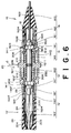
- a connecting adapter 20'' is basically the same as that of Fig. 6.
- an elastic sleeve 210'' on the right side in Fig. 8 is formed shorter than that of Fig. 6. Because the remaining structure is the same as that to Fig. 6, members whose constructions are identical with those of the connecting adapter 20 set forth above are assigned like reference numerals but with double primes "''" to simplify the discussion.
- the front end of the ferrule 14' is inserted into the elastic sleeve 210'' with the guide cylinder 1611' guided along the outer circumference of the elastic sleeve 210'', and then the locking claws 208'' engage with the locking notch 1612', resulting in the optical connector plug 10' is held in a predetermined position.
- associated parts are dimensioned such that the front surface of the ferrule 14' slightly projects from the center plane C of the connecting adapter 20'' and positions in a first predetermined position by being biassed by the spring 28.
- the front end of the ferrule 14'' is inserted into the elastic sleeve 210'', and then the locking claws 208'' engage the shoulder portion of the first flange 1411'' with a large diameter, resulting in the optical connector plug 10'' is held in a predetermined position.
- the front surface of the ferrule 14'' initially comes in contact with the front surface of the ferrule 14' which is held in the first predetermined position and then deflects the spring 28, resulting in the front surfaces of both the ferrules 14', 14'' which are connected being positioned in the center plane C (second position) of the connecting adapter 20''.
- the optical connector plug having the immovable ferrule in use with the optical connector plug having the immovable ferrule set forth above, it is preferable that the optical connector plug having the movable ferrule is disposed on an instrument and the optical connector plug having the movable ferrule, as the optical connector plug which is frequently connected and disconnected, connected to the instrument.
- a refractive index matching agent is coated on a connecting surface at the time of connection so as to exist between connecting surfaces of the optical connector plugs 10, 10' or 10''.
Landscapes
- Physics & Mathematics (AREA)
- General Physics & Mathematics (AREA)
- Optics & Photonics (AREA)
- Mechanical Coupling Of Light Guides (AREA)
Abstract
Description
- The present invention relates to an optical connector for connecting optical fibers, and more particularly to a plug-adapter-plug type optical connector for connecting plugs through an adapter and also to an optical connector plug thereof.
- Among the known conventional plug-adapter-plug type optical connectors are an FC connector of JIS C 5970 F01 type, an SC connector of JIS C 5973 F01, and an MPO connector disclosed in Japanese Utility Model Publication No. 4-49606 and Japanese Patent Application laid-Open No. 4-347806.
- Because these optical connectors are assumed to be connected and disconnected frequently, they are required to have a function to position an optical fiber with high precision and a function to maintain the close junction between optical fibers. To maintain the close junction between optical fibers, a ferrule in a housing of each connector plug is made axially movable and is biassed from the rear by a coil spring. When the connector plugs are coupled, the ferrule is moved rearwardly against a biassing force to produce a predetermined pressing force. The optical fiber cord used on this connector is a so-called tension-resistant fiber-covered optical fiber cord, which, as shown in Fig. 4, includes: a secondary coated optical fiber made up of a primary coated optical fiber (a bare optical fiber) covered with an optical fiber jacket of resin; a tension-resistant fiber enclosing the secondary coated optical fiber; and an optical cord jacket enclosing all these.
- The end of the tension-resistant fiber is secured to the housing to prevent the secondary coated optical fiber from being tensed.
- In recent years, the conventional tension-resistant fiber-covered optical fiber cords are being increasingly replaced with a new type of optical fiber cord (hereinafter referred to as a tension-resistant jacket-covered optical fiber cord) in which, as shown in Fig. 2, an optical cord jacket is directly fitted substantially tightly over the secondary coated optical fiber and is provided with a tension resisting capability.
- When such a tension-resistant jacket-covered optical fiber cord is applied to the conventional optical connector plug, however, the optical cord jacket is directly fixed to the ferrule and also to the housing. This gives rise to a problem that the retraction of the ferrule at the time of connector coupling results in the optical fiber being bent locally with a small radius of curvature, leading to increased losses and deteriorated reliability. Possible means to avoid this problem may include not fixing the optical cord jacket to the housing. But this will further retract the ferrule when the optical fiber cord is subjected to tension, rendering the joint unstable and, in the worst case, dislodging the fibers out of joint, which in turn results in an increase in connection losses and reflected light.
- A primary object of this invention is to solve the aforementioned problems experienced with the prior art and to provide an optical connector plug and an optical connector that can stably couple even a tension-resistant jacket-covered optical fiber cord.
- To accomplish the object, in a first aspect of the present invention, there is provided an optical connector plug comprising:
- a ferrule fixed to an end of an optical fiber cord which has a secondary coated optical fiber and a tension-resistant jacket covering the secondary coated optical fiber;
- a housing accommodating the ferrule; and
wherein the secondary coated optical fiber and the tension-resistant jacket of the optical fiber cord are secured to the ferrule and the ferrule is axially immovably mounted to the housing. - Here, the housing may comprise a plug frame, a stop sleeve and an elastic hood.
- Further, the tension-resistant jacket of the optical fiber cord may be bonded to a rear end portion of the elastic hood of the housing.
- On the other hand, the housing may be integrally formed with an adapter to which a mating optical connector plug to be connected are inserted.
- In another aspect of the present invention, there is provided an optical connector comprising:
- an optical connector plug comprising:
- a ferrule fixed to an end of an optical fiber cord which has a secondary coated optical fiber and a tension-resistant jacket covering the secondary coated optical fiber;
- a housing accommodating the ferrule; and
wherein the secondary coated optical fiber and the tension-resistant jacket of the optical fiber cord are secured to the ferrule and the ferrule is axially immovably mounted to the housing; and
- a connecting adapter which mutually connects a pair of the optical connector plugs.
- Here, the connecting adapter may comprise means for axially biassing the pair of optical connector plugs so as to connect to each other.
- In still another aspect of the present invention, there is provided an optical connector plug comprising:
- a ferrule fixed to an end of an optical fiber cord which has a secondary coated optical fiber and a tension-resistant jacket covering the secondary coated optical fiber;
- a housing accommodating the ferrule; and
wherein said secondary coated optical fiber and said tension-resistant jacket of the optical fiber cord are secured to said ferrule; and said ferrule is axially immovably mounted to said housing; - an optical connector plug comprising:
- a ferrule fixed to an end of an optical fiber cord which has a secondary coated optical fiber and a tension-resistant jacket covering the secondary coated optical fiber;
- a housing accommodating the ferrule; and
wherein said secondary coated optical fiber and said tension-resistant jacket of the optical fiber cord are secured to said ferrule; and said ferrule is axially movably mounted to said housing; and
- a connecting adapter which mutually connects both said optical connector plugs.
- Here, a refraction index matching agent may be coated on a connecting surface of the optical connector plugs to be mutually connected.
- According to the invention, in an optical connector, which includes an optical connector plug having a ferrule holding an optical fiber and a housing accommodating the ferrule, and an adapter connecting the optical connector plugs, an optical fiber cord has a construction wherein at least a jacket carries tension, a secondary coated optical fiber of the optical fiber cord and the jacket carrying the tension are secured to the ferrule, and the ferrule is immovably mounted to the housing. This construction prevents local bending of the secondary coated optical fiber at the time of coupling and disconnection when the optical fiber cord is subjected to tension
-
- Fig. 1 is a cross sectional view showing an embodiment of the invention;
- Fig. 2 is a cross sectional view showing an example of an optical fiber cord used in an optical connector of the invention whose jacket carries tension;
- Fig. 3 is a cross sectional view showing an optical connector of the invention in a coupled state;
- Fig. 4 is a cross sectional view showing an example of an optical fiber cord having a tension-resistant fiber;
- Fig. 5 is a cross sectional view showing a state in which an optical fiber cord is fixed to a ferrule;
- Fig. 6 is a cross sectional view showing an optical connector of the invention in another coupled state;
- Fig. 7 is a cross sectional view showing an example of a connecting adapter used for an optical connector of the invention and a coupled state thereof; and
- Fig. 8 is a cross sectional view showing an optical connector of the invention in still another coupled state.
- The present invention will be described in detail in conjunction with preferred embodiments illustrated in the accompanying drawings.
- Fig. 1 shows an embodiment of an
optical connector plug 10 according to the invention which comprises aferrule 14 and ahousing 16 which houses and holds the ferrule. - In Fig. 1, designated 12 is an optical fiber cord that has a cross sectional structure shown in Fig. 2. This is a tension-resistant jacket-covered optical fiber cord, which includes: a secondary coated
optical fiber 120 consisting of a primary-coated (bare) optical fiber 121 covered with anoptical fiber jacket 122 of resin; and anoptical cord jacket 123 directly fitted substantially tightly over the secondary coatedoptical fiber 120 and provided with a capability to carry tension. The end of theoptical fiber cord 12 is secured to theferrule 14 such that the secondary coatedoptical fiber 120 stripped of theoptical cord jacket 123 is exposed at the front end surface of theferrule 14, as particularly shown in Fig. 5. At the same time, thejacket 123 is also adhesively fixed to the rear end of theferrule 14. Theferrule 14 has an elongatedcylindrical body 140 and acap member 141, fitted to thebody 140, forming a disk-shaped flange 1411 at the middle of theferrule 14. Apositioning notch 1412 is formed on the disk-shaped flange 1411 (see Fig. 1). - In the shown case, the
optical cord jacket 123 is stripped at its distal end, however it should be appreciated that theoptical fiber cord 12 can be exposed at the front end surface of theferrule 14 without theoptical cord jacket 123 being striped. Further, the disc-like flange 1411 is not necessary to be cylindrical and may be non-cylindrical. - Referring again to Fig. 1, the
housing 16 in this embodiment comprises aplug frame 161, astop sleeve 162, and a resilient hood, for example, arubber hood 163. - The
plug frame 161 has aguide cylinder portion 1611 at the front end, anannular locking notch 1612 for engagement with the adapter etc. on the outer circumference, astepped portion 1613 on the inner circumference to receive the disk-shaped flange 1411 of theferrule 14, and aguide cylinder portion 1614 at the rear end. The rearguide cylinder portion 1614 has lockingholes 1615 180 degrees apart. - The
stop sleeve 162 comprises aguide cylinder portion 1621 fitted into the rearguide cylinder portion 1614 of theplug frame 161,projections 1622 formed on the outer circumference and engaged in the locking holes 1615, a steppedportion 1623 formed on the inner circumference, and arestriction cylinder 1624 at the rear end. -
Denoted 18 is a cylindrical spacer which is disposed between the steppedportion 1623 of thestop sleeve 162 and theflange 1411 of theferrule 14 so as to immovably fix theferrule 14 in thehousing 16. However, it may be possible to omit thespacer 18 by forming the steppedportion 1623 up to the position corresponding to the length of thespacer 18 at the time of molding thestop sleeve 162, and abutting thus formed stepped portion directly against theflange 1411 of theferrule 14. In other words, thestop sleeve 162 and thespacer 18 may be integrally molded. - With the structure set forth above, the
ferrule 14 to which theoptical fiber cord 12 is secured is inserted into theplug frame 161, with theflange 1411 of theferrule 14 being positioned by thenotch 1412 and seated on the steppedportion 1613. Then, thestop sleeve 162, together with thespacer 18, is inserted into theplug frame 161 to fit itsguide cylinder portion 1621 into the rearguide cylinder portion 1614 of theplug frame 161 until theprojections 1622 engage in the locking holes 1615. This causes theflange 1411 to be clamped between the steppedportion 1613 of theplug frame 161 and one end of thespacer 18 whose other end engages the steppedportion 1623 of thestop sleeve 162, with the result that theferrule 14 is held axially immovable by theplug frame 161 and thestop sleeve 162. - Further, the front end of the
rubber hood 163 is adhesively bonded to the rear end of theplug frame 161. Theoptical fiber cord 12 extends outside through aninsertion hole 1631 in therubber hood 163. In this manner, theferrule 14 having theoptical fiber cord 12 fixed thereto is secured to thehousing 16 so that it cannot be moved in the direction of the optical axis of the fiber. As a result, theoptical fiber cord 12 is directly fixed to thehousing 16 Further, any effects to connected portions caused by torsion of theoptical fiber cord 12 can be eliminated by adhesively bonding theoptical fiber cord 12 to therubber hood 163 in theinsertion hole 1631. - The above-mentioned optical connector plug 10 of this invention, used in combination with an
adapter 20 of Fig. 3, constitutes an optical connector. - When the optical connector plug 10 of this invention in which the ferrule is axially immovable with respect to the housing is used, although the same type of the
optical connector plug 10 may be used in pair as in the case of Fig. 7 described later, it is preferred that the mating optical connector plug 10' be of a type that, when pushed, allows the ferrule 14' to be moved axially. Now, we will explain about the mating optical connector plug 10'. The members whose constructions are identical with those of theoptical connector plug 10 are assigned like reference numerals but with a prime "'" and repetitive descriptions are not given. - The
optical fiber cord 22 used in the optical connector plug 10' is a so-called tension-resistant fiber-covered optical fiber cord, which, as shown in Fig. 4, comprises: a secondary coatedoptical fiber 220 made up of a primary coatedoptical fiber 221 and anoptical fiber jacket 222 of resin covering the primary coatedoptical fiber 221; a tension-resistant fiber 223 enclosing the secondary coatedoptical fiber 220; and anoptical cord jacket 224 enclosing these. - The secondary coated
optical fiber 220 of theoptical fiber cord 22 is secured at one end to the ferrule 14', with the secondary coatedoptical fiber 220 stripped of theoptical cord jacket 224 and tension-resistant fiber 223 and exposed at the front end surface of the ferrule 14'. The tension-resistant fiber 223 is caulked and secured to a restriction cylinder 1624' of a stop sleeve 162' by afirst retainer tube 24 and theoptical cord jacket 224 is caulked and secured to the rear small-diameter portion of thefirst retainer tube 24 by asecond retainer tube 26, resulting in both being secured to the housing 16'. - The ferrule 14' has a cylindrical body 140' and a cap member 141' as well as a cylindrical or non-cylindrical disk-shaped flange 1411' as set forth above at the intermediate portion, which has a positioning notch 1412'.
- A housing 16' comprises a plug frame 161', a stop sleeve 162' and a rubber hood 163'.
- The plug frame 161' has a guide cylinder portion 1611' at the front end, an annular locking notch 1612' on the outer circumference, a stepped portion 1613' on the inner circumference to accommodate and hold the disk-shaped flange 1411' of the ferrule 14', and a guide cylinder portion 1614' at the rear end. The guide cylinder portion 1614' is formed with locking holes 1615' 180 degrees apart from each other.
- The stop sleeve 162' comprises a guide cylinder portion 1621' fitted into the rear guide cylinder portion 1614' of the plug frame 161', projections 1622' formed on the outer circumference and engaged in the locking holes 1615', a stepped portion 1623' formed on the inner circumference, and a restriction cylinder 1624' at the rear end.
- Designated 28 is a coil spring, which is disposed between the flange 1411' of the ferrule 14' and the stepped portion 1623' of the stop sleeve 162'. The ferrule 14' is movably biassed by this
spring 28 so as to allow the flange 1411' to abut against the stepped portion 1613' of the plug frame 161'. - The front end of the rubber hood 163' is adhesively bonded to the rear end of the plug frame 161'. As previously discussed in the optical connector plug 10', the ferrule 14' having the secondary coated
optical fiber 220 fixed thereto is movably mounted in the housing 16', with the end of the tension-resistant fiber 223 secured to the housing 16' so that tension is not applied to the secondary coatedoptical fiber 220. - Optical connection is made by inserting such optical connector plugs 10 and 10' from opposite sides of the connecting
adapter 20. - The connecting
adapter 20 is formed, for example as shown in Fig. 3, symmetrical with respect to the center plane C and accommodates asleeve holder 206 inside acylindrical housing 204 formed with asupport portion 202 which serves as a mount portion on a panel and the like or a knob. Thesleeve holder 206 has a pair of left and right radially resilient lockingclaws 208 formed integral therewith and holds a cylindricalelastic sleeve 210 concentric with thecylindrical housing 204. - When the
optical connector plug 10 is inserted from one end of the connectingadapter 20, the front end of theferrule 14 is inserted into theelastic sleeve 210 with theguide cylinder portion 1611 guided along the outer circumference of theelastic sleeve 210 until the lockingclaws 208 engage with theannular locking notch 1612, at which time theoptical connector plug 10 is held in position. The dimensions of these members are so set that, with theoptical connector plug 10 held in place, the front end surface of theferrule 14 is flush with the center plane C of theadapter 20. - Next, as the optical connector plug 10' is inserted from the other end of the connecting
adapter 20, the front end of the ferrule 14' is inserted into theelastic sleeve 210 with the guide cylinder portion 1611' guided along the outer circumference of theelastic sleeve 210 until the lockingclaws 208 engage with the annular locking notch 1612'. As a result, the optical connector plug 10' is held in position. At this time the front end surface of the ferrule 14' comes in contact with the front end surface of theferrule 14 and then deflects thespring 28. In this way, the biassing force of thespring 28 of the optical connector plug 10' gives a closely connected condition betweenferrules 14 and 14' and prevents connection losses in optical connection from increasing. - The connecting
adapter 20 may be formed integral with either of the plug frames 161 and 161', which makes up a part of thehousing 16 or 16' of theoptical connector plug 10 or 10'. In this case, the mating optical connector plug is inserted into theadapter 20 thus formed integral with the optical connector plug. Here, the term "to form integral" means to include both "to form the plug frame and the adapter by integrally molding them" and "to form the plug frame and the adapter separately and then integrate them by bonding". This simplifies the coupling procedure. - Here, another embodiment of the connecting adapter will be discussed referring to Fig. 7. The members whose constructions are identical with those of the connecting
adapter 20 set forth above are assigned like reference numerals but with a prime "'" to simplify the discussion. - The connecting adapter 20' shown in Fig. 7 is constructed such that a biassing force can be applied axially in either of directions to ensure the mutual connection of the optical connector plugs to be connected. To this end, the connecting adapter 20' in this embodiment comprises an
enlarged sleeve 212 which is radially enlarged to define acylindrical space 214 inside a portion on the left side with respect to the center plane C in Fig. 7 in comparison with thesleeve holder 206 set force above. Further, lockingclaws 2080 which are connected to each other by aflange 2081 are axially movably provided within thecylindrical space 214. The lockingclaws 2080 are axially biassed by aspring 216 at theflange 2081 in the right direction as illustrated. - With the connecting adapter 20' as constructed above, when the
optical connector plug 10 is inserted from one end, on the left side, of the adapter, the front end of theferrule 14 is inserted into the elastic sleeve 210' with theguide cylinder 1611 guided along the outer circumference of theelastic sleeve 210, and then the lockingclaws 2080 engage with thelocking notch 1612, resulting in theoptical connector plug 10 is held in a first predetermined position where the front surface of theferrule 14 slightly projects from the center plane C of the connecting adapter 20'. Next, as the same type ofoptical connector plug 10 is inserted from the other end, on the right side, of the connecting adapter 20' in a like manner, the front end of theferrule 14 is inserted into the elastic sleeve 210' with theguide cylinder 1611 guided along the outer circumference of the elastic sleeve 210', and then the locking claws 208' engage thelocking notch 1612, resulting in theoptical connector plug 10 is held in a second predetermined position. - More specifically, the front surface of the
ferrule 14 inserted from the right side at first comes in contact with the front surface of theferrule 14 inserted form the left side which is held in the first predetermined position, and then deflects thespring 216. When both of the front surfaces of the right and leftferrules 14 are positioned in the center plane C, i.e. the second predetermined position, the locking claws 208' are engaged with thelocking notch 1612. Thus, even when connecting the optical connector plugs 10, 10 in each of which the ferrule is not axially movable with respect to the housing, it is possible to maintain a closely connected condition betweenferrules spring 216. -
Denoted 230 is a split sleeve, which is optionally provided within the elastic sleeve 210', made of, for example, phosphor bronze or zirconia. Thesplit sleeve 230 is used to enhance radial precession of the ferrules to be coupled. - Another embodiment of the invention will be described referring to Fig. 8.
- An optical connector plug 10'' according to this embodiment is intended to simplify its structure and to reduce costs by omitting the plug frame and the stop sleeve from the housing of the above mentioned embodiments. As a result, only a portion of a ferrule is accommodated within a housing.
- A ferrule 14'' of the optical connector plug 10'' according to this embodiment in which the ferrule is immovable comprises an elongated cylindrical body 140'' and a cap member 141'', which is fitted to the body 140'', forming a first flange 1411'' with a large diameter at the middle portion of the ferrule 14'' and a second flange 1413'' with a small diameter at the rear portion of the ferrule 14''. A relationship in connection between the ferrule body 140'' and both the secondary coated
optical fiber 120 and theoptical cord jacket 123 of theoptical fiber cord 12 is the same as that of the previous embodiment which is discussed referring to Fig. 5. Between the first flange 1411'' and the second flange 1413'' is formed an annular groove 1414''. Then, the front end of a housing 16'' consisting of a rubber hood 163'' is engaged within the annular groove 1414'' and adhesively bonded to the cap member 141'' of the ferrule 14''. - On the other hand, the structure of a connecting adapter 20'' is basically the same as that of Fig. 6. However, since the optical connector plug 10'' of this embodiment does not have a plug frame, an elastic sleeve 210'' on the right side in Fig. 8 is formed shorter than that of Fig. 6. Because the remaining structure is the same as that to Fig. 6, members whose constructions are identical with those of the connecting
adapter 20 set forth above are assigned like reference numerals but with double primes "''" to simplify the discussion. - When the optical connector plug 10' having an axially movable ferrule is inserted from the left end of the connecting adapter 20'', the front end of the ferrule 14' is inserted into the elastic sleeve 210'' with the guide cylinder 1611' guided along the outer circumference of the elastic sleeve 210'', and then the locking claws 208'' engage with the locking notch 1612', resulting in the optical connector plug 10' is held in a predetermined position. At this time, associated parts are dimensioned such that the front surface of the ferrule 14' slightly projects from the center plane C of the connecting adapter 20'' and positions in a first predetermined position by being biassed by the
spring 28. Next, as the optical connector plug 10'' is inserted from the right end of the connecting adapter 20'', the front end of the ferrule 14'' is inserted into the elastic sleeve 210'', and then the locking claws 208'' engage the shoulder portion of the first flange 1411'' with a large diameter, resulting in the optical connector plug 10'' is held in a predetermined position. At this time, the front surface of the ferrule 14'' initially comes in contact with the front surface of the ferrule 14' which is held in the first predetermined position and then deflects thespring 28, resulting in the front surfaces of both the ferrules 14', 14'' which are connected being positioned in the center plane C (second position) of the connecting adapter 20''. Thus, it is possible to maintain a closely connected condition between ferrules 14' and 14'' and prevent connection losses in optical connection from increasing by utilizing the axial biassing force of thespring 28. - On the other hand, in use with the optical connector plug having the immovable ferrule set forth above, it is preferable that the optical connector plug having the movable ferrule is disposed on an instrument and the optical connector plug having the movable ferrule, as the optical connector plug which is frequently connected and disconnected, connected to the instrument.
- Further, a refractive index matching agent is coated on a connecting surface at the time of connection so as to exist between connecting surfaces of the optical connector plugs 10, 10' or 10''. By this, it would be possible to reduce the increase of connection losses caused by a gap between the connecting surfaces of the optical connector plugs.
Claims (8)
- An optical connector plug characterized by comprising:a ferrule fixed to an end of an optical fiber cord which has a secondary coated optical fiber and a tension-resistant jacket covering the secondary coated optical fiber;a housing accommodating the ferrule; and
wherein said tension-resistant jacket of said optical fiber cord is secured to said ferrule and said ferrule is axially immovably mounted to said housing. - An optical connector plug according to claim 1, characterized in that said housing comprises a plug frame, a stop sleeve and an elastic hood.
- An optical connector plug according to claim 2, characterized in that said tension-resistant jacket of said optical fiber cord is bonded to a rear end portion of said elastic hood of said housing.
- An optical connector plug according to claim 1, characterized in that said housing is integrally formed with an adapter to which a mating optical connector plug to be connected is inserted.
- An optical connector characterized by comprising:an optical connector plug characterized by comprising:a ferrule fixed to an end of an optical fiber cord which has a secondary coated optical fiber and a tension-resistant jacket covering the secondary coated optical fiber;a housing accommodating the ferrule; and
wherein said secondary coated optical fiber and said tension-resistant jacket of the optical fiber cord are secured to said ferrule and said ferrule is axially in movably mounted to said housing; anda connecting adapter which mutually connects a pair of said optical connector plugs. - An optical connector according to claim 5, characterized in that said connecting adapter comprises means for axially biassing said pair of optical connector plugs so as to connect to each other.
- An optical connector characterized by comprising:an optical connector plug characterized by comprising:a ferrule fixed to an end of an optical fiber cord which has a secondary coated optical fiber and a tension-resistant jacket covering the secondary coated optical fiber;a housing accommodating the ferrule; and
wherein said secondary coated optical fiber and said tension-resistant jacket of the optical fiber cord are secured to said ferrule; and said ferrule is axially immovably mounted to said housing;an optical connector plug characterized by comprising:a ferrule fixed to an end of an optical fiber cord which has a secondary coated optical fiber and a tension-resistant jacket covering the secondary coated optical fiber;a housing accommodating the ferrule; and
wherein said secondary coated optical fiber and said tension-resistant jacket of the optical fiber cord are secured to said ferrule; and said ferrule is axially movably mounted to said housing; anda connecting adapter which mutually connects both said optical connector plugs. - An optical connector according to any one of claims 5,6 or 7, characterized in that a refraction index matching agent is coated on a connecting surface of the optical connector plugs to be mutually connected.
Applications Claiming Priority (3)
| Application Number | Priority Date | Filing Date | Title |
|---|---|---|---|
| JP17620895 | 1995-07-12 | ||
| JP176208/95 | 1995-07-12 | ||
| PCT/JP1996/001922 WO1997003374A1 (en) | 1995-07-12 | 1996-07-11 | Optical fiber connector plug and optical fiber connector |
Publications (2)
| Publication Number | Publication Date |
|---|---|
| EP0784218A1 true EP0784218A1 (en) | 1997-07-16 |
| EP0784218A4 EP0784218A4 (en) | 1999-09-08 |
Family
ID=16009520
Family Applications (1)
| Application Number | Title | Priority Date | Filing Date |
|---|---|---|---|
| EP96923054A Ceased EP0784218A4 (en) | 1995-07-12 | 1996-07-11 | FIBER OPTICAL PLUG AND PLUG |
Country Status (5)
| Country | Link |
|---|---|
| US (1) | US5862282A (en) |
| EP (1) | EP0784218A4 (en) |
| AU (1) | AU685710B2 (en) |
| CA (1) | CA2199711C (en) |
| WO (1) | WO1997003374A1 (en) |
Cited By (3)
| Publication number | Priority date | Publication date | Assignee | Title |
|---|---|---|---|---|
| EP0811861A1 (en) * | 1996-06-07 | 1997-12-10 | Molex Incorporated | Adaptor for interconnecting optical fibers |
| WO2009130160A1 (en) * | 2008-04-21 | 2009-10-29 | Huber+Suhner Ag | Optical connector |
| EP2282229A1 (en) * | 2009-08-07 | 2011-02-09 | CCS Technology, Inc. | Connectorized optical assembly and method for connecting optical transceiver units by an optical assembly |
Families Citing this family (45)
| Publication number | Priority date | Publication date | Assignee | Title |
|---|---|---|---|---|
| US5872879A (en) * | 1996-11-25 | 1999-02-16 | Boston Scientific Corporation | Rotatable connecting optical fibers |
| US6454464B1 (en) | 1998-12-28 | 2002-09-24 | Computer Crafts, Inc. | Fiber optic connectors and transceiver test devices |
| US6464408B1 (en) | 1998-12-28 | 2002-10-15 | Computer Crafts, Inc. | Fiber optic connectors |
| US6283640B1 (en) * | 1999-04-01 | 2001-09-04 | Lucent Technologies Inc. | Tunable optical fiber buildout |
| EP1079251B1 (en) * | 1999-08-25 | 2005-11-02 | Interlemo Holding S.A. | A method for manufacturing a fibre optic male contact |
| US6565264B1 (en) | 2000-01-18 | 2003-05-20 | Amphenol Corporation | Pin and socket fiber optic termini |
| JP2001290047A (en) * | 2000-02-04 | 2001-10-19 | Seiko Instruments Inc | Flange member and ferrule |
| US6572276B1 (en) * | 2000-11-21 | 2003-06-03 | Euromicron Werkezeuge Gmbh | Plug for fiber optic cables with a plug housing |
| JP2003207687A (en) * | 2002-01-16 | 2003-07-25 | Seiko Instruments Inc | Ferrule and its manufacturing method and optical connector plug |
| US6776533B2 (en) * | 2002-02-19 | 2004-08-17 | Itt Manufacturing Enterprises, Inc. | Latching fiber optic connector system |
| US6863446B2 (en) | 2002-03-05 | 2005-03-08 | Fci Americas Technology, Inc. | Optical connector adapter with latch inserts |
| US6935789B2 (en) * | 2003-03-11 | 2005-08-30 | Itt Manufacturing Enterprises, Inc. | Fiber optic connector with long terminus movement and moderate length |
| JP2005301151A (en) * | 2004-04-15 | 2005-10-27 | Canare Electric Co Ltd | Optical contact unit and optical plug |
| JP2008152196A (en) * | 2006-12-20 | 2008-07-03 | Mitsubishi Cable Ind Ltd | Mechanism for connecting optical fibers |
| US7534050B2 (en) | 2007-04-13 | 2009-05-19 | Adc Telecommunications, Inc. | Field terminatable fiber optic connector assembly |
| US8002774B2 (en) * | 2007-11-07 | 2011-08-23 | Stryker Corporation | Bone mill including a base and a mill head separate from the base, the mill head including a moveable catch tray |
| CN102439502B (en) * | 2009-04-06 | 2015-02-18 | Adc电信公司 | Fiber optic connector and method for assembling |
| US20110091166A1 (en) * | 2009-10-15 | 2011-04-21 | Seldon David Benjamin | Fiber Optic Connectors and Structures for Large Core Optical Fibers and Methods for Making the Same |
| US8998502B2 (en) * | 2010-09-03 | 2015-04-07 | Corning Incorporated | Fiber optic connectors and ferrules and methods for using the same |
| US8702323B2 (en) | 2011-03-15 | 2014-04-22 | Adc Telecommunications, Inc. | Strain relief boot for a fiber optic connector |
| US8636425B2 (en) | 2011-03-15 | 2014-01-28 | Adc Telecommunications, Inc. | Fiber optic connector |
| US20140016900A1 (en) * | 2011-04-11 | 2014-01-16 | Autonetworks Technologies, Ltd. | Optical connector and ferrule |
| JP2012220799A (en) * | 2011-04-11 | 2012-11-12 | Furukawa Electric Co Ltd:The | Optical fiber terminal, optical fiber cable with terminal, optical connector, and optical fiber cable with connector |
| JP2012220798A (en) * | 2011-04-11 | 2012-11-12 | Furukawa Electric Co Ltd:The | Optical fiber terminal, optical fiber cable with terminal, optical connector, and optical fiber cable with connector |
| CN104364686B (en) | 2012-02-07 | 2016-11-16 | 泰科电子瑞侃有限公司 | Cable termination assembly and method for adapter |
| US9176285B2 (en) | 2012-05-03 | 2015-11-03 | Adc Telecommunications, Inc. | Fiber optic connector |
| US9921373B2 (en) * | 2013-12-19 | 2018-03-20 | Exfo Inc. | Fiber-optic connector mating assembly for optical test instruments |
| JP2016194602A (en) * | 2015-03-31 | 2016-11-17 | 株式会社フジクラ | Cable equipment |
| JP6492972B2 (en) * | 2015-05-27 | 2019-04-03 | 日立金属株式会社 | Communication light visualization code |
| JP6447371B2 (en) * | 2015-06-04 | 2019-01-09 | 日立金属株式会社 | Communication light visualization code and communication light detector |
| CN109073838B (en) | 2016-03-10 | 2021-03-30 | 康宁光电通信有限责任公司 | Ferrule-based fiber optic connector with ferrule retraction balance |
| US10718911B2 (en) | 2017-08-24 | 2020-07-21 | Senko Advanced Components, Inc. | Ultra-small form factor optical connectors using a push-pull boot receptacle release |
| US12001064B2 (en) | 2017-07-14 | 2024-06-04 | Senko Advanced Components, Inc. | Small form factor fiber optic connector with multi-purpose boot |
| US10281668B2 (en) | 2017-07-14 | 2019-05-07 | Senko Advanced Components, Inc. | Ultra-small form factor optical connectors |
| US11822133B2 (en) | 2017-07-14 | 2023-11-21 | Senko Advanced Components, Inc. | Ultra-small form factor optical connector and adapter |
| US11002923B2 (en) | 2017-11-21 | 2021-05-11 | Senko Advanced Components, Inc. | Fiber optic connector with cable boot release having a two-piece clip assembly |
| CN115201974B (en) * | 2017-12-19 | 2024-04-30 | 美国康涅克有限公司 | Miniature duplex connector with push-pull polarity mechanism and carrier |
| EP3776038B1 (en) | 2018-03-28 | 2024-07-03 | Senko Advanced Components Inc. | Small form factor fiber optic connector with multi-purpose boot |
| US11073664B2 (en) | 2018-08-13 | 2021-07-27 | Senko Advanced Components, Inc. | Cable boot assembly for releasing fiber optic connector from a receptacle |
| CN112955797B (en) | 2018-09-12 | 2022-11-11 | 扇港元器件股份有限公司 | LC type connector with clip-on push/pull tab for releasing connector from receptacle with cable jacket |
| US10921531B2 (en) | 2018-09-12 | 2021-02-16 | Senko Advanced Components, Inc. | LC type connector with push/pull assembly for releasing connector from a receptacle using a cable boot |
| US10921530B2 (en) | 2018-09-12 | 2021-02-16 | Senko Advanced Components, Inc. | LC type connector with push/pull assembly for releasing connector from a receptacle using a cable boot |
| US11340406B2 (en) | 2019-04-19 | 2022-05-24 | Senko Advanced Components, Inc. | Small form factor fiber optic connector with resilient latching mechanism for securing within a hook-less receptacle |
| CN114026480B (en) | 2019-06-13 | 2023-05-26 | 扇港元器件有限公司 | Lever actuated latch arm for releasing fiber optic connectors from receptacle ports and method of use |
| US11320600B2 (en) | 2019-09-12 | 2022-05-03 | Corning Research & Development Corporation | Fiber optic connector for hardware interiors and method of using same |
Family Cites Families (12)
| Publication number | Priority date | Publication date | Assignee | Title |
|---|---|---|---|---|
| JPS5693510A (en) * | 1979-12-03 | 1981-07-29 | Fujitsu Ltd | Mold core |
| JPS5730714U (en) * | 1980-07-30 | 1982-02-18 | ||
| JPS59141308U (en) * | 1983-03-10 | 1984-09-21 | 第一電子工業株式会社 | Multi-core optical fiber cable connector |
| US4747658A (en) * | 1983-03-14 | 1988-05-31 | International Telephone And Telegraph Corporation | Fiber optic contact |
| JPS63179304A (en) * | 1987-01-20 | 1988-07-23 | Fuji Electric Co Ltd | Optical connector for reflection type light applied sensor system |
| JPH0442805Y2 (en) * | 1987-04-30 | 1992-10-09 | ||
| JPS6413013U (en) * | 1987-07-15 | 1989-01-24 | ||
| JPS6463910A (en) * | 1987-09-04 | 1989-03-09 | Mitsubishi Rayon Co | Optical fiber with integrated optical connector plug |
| US5231685A (en) * | 1989-11-28 | 1993-07-27 | Kel Corporation | Multi-way electro-optic connector assemblies and optical fiber ferrule assemblies therefor |
| US5170452A (en) * | 1991-09-09 | 1992-12-08 | Porta Systems Corp. | Fiber optic plug connector and adapter therefor |
| GB9307488D0 (en) * | 1993-04-08 | 1993-06-02 | Amp Holland | Optical fibre connector latching mechanism |
| US5719977A (en) * | 1996-04-23 | 1998-02-17 | Lucent Technologies Inc. | Optical connector with immovable ferrule |
-
1996
- 1996-07-11 AU AU63690/96A patent/AU685710B2/en not_active Ceased
- 1996-07-11 EP EP96923054A patent/EP0784218A4/en not_active Ceased
- 1996-07-11 CA CA002199711A patent/CA2199711C/en not_active Expired - Fee Related
- 1996-07-11 WO PCT/JP1996/001922 patent/WO1997003374A1/en not_active Ceased
- 1996-07-11 US US08/809,744 patent/US5862282A/en not_active Expired - Fee Related
Cited By (4)
| Publication number | Priority date | Publication date | Assignee | Title |
|---|---|---|---|---|
| EP0811861A1 (en) * | 1996-06-07 | 1997-12-10 | Molex Incorporated | Adaptor for interconnecting optical fibers |
| US5815618A (en) * | 1996-06-07 | 1998-09-29 | Molex Incorporated | Adaptor for interconnecting optical fibers |
| WO2009130160A1 (en) * | 2008-04-21 | 2009-10-29 | Huber+Suhner Ag | Optical connector |
| EP2282229A1 (en) * | 2009-08-07 | 2011-02-09 | CCS Technology, Inc. | Connectorized optical assembly and method for connecting optical transceiver units by an optical assembly |
Also Published As
| Publication number | Publication date |
|---|---|
| AU685710B2 (en) | 1998-01-22 |
| AU6369096A (en) | 1997-02-10 |
| CA2199711A1 (en) | 1997-01-30 |
| CA2199711C (en) | 2003-01-07 |
| EP0784218A4 (en) | 1999-09-08 |
| WO1997003374A1 (en) | 1997-01-30 |
| US5862282A (en) | 1999-01-19 |
Similar Documents
| Publication | Publication Date | Title |
|---|---|---|
| US5862282A (en) | Optical connector plug and optical connector | |
| EP0997757B1 (en) | Cylindrical connector incorporating a rectangular optical fibre ferrule | |
| JP2928101B2 (en) | Fiber optic connectors | |
| US7270487B2 (en) | Field installable optical fiber connector | |
| EP0928978B1 (en) | Connector for plastic optical fiber | |
| CN1054919C (en) | Pull-proof, modular fiber optic connector system | |
| EP0731369B1 (en) | Receptacle for optical fibre connection and method of manufacturing the same | |
| US4684205A (en) | Fiber optic connector with compensating mechanism | |
| US6347888B1 (en) | Fiber optic adapter, including hybrid connector system | |
| EP0088410B1 (en) | Optical fiber connectors | |
| US5953475A (en) | Fiber optic plug connector | |
| US12411288B2 (en) | Fiber optic connector having flattened regions that face and align to prevent rotation | |
| US12055767B2 (en) | Pushable optical connector with connector-integrated articulation | |
| US5450514A (en) | Optical waveguide terminating sleeve usable with optical waveguide connectors | |
| US12422625B2 (en) | Optical fiber connector for minimizing signal transmission losses | |
| US6565264B1 (en) | Pin and socket fiber optic termini | |
| WO1994000785A2 (en) | Optical waveguide terminating sleeve | |
| EP0024959B1 (en) | Connector for optical waveguides | |
| JPH0435845Y2 (en) | ||
| JPWO1997003374A1 (en) | Optical connector plug and optical connector | |
| WO2026055656A1 (en) | Multi-fiber hardened fiber optic connection systems |
Legal Events
| Date | Code | Title | Description |
|---|---|---|---|
| PUAI | Public reference made under article 153(3) epc to a published international application that has entered the european phase |
Free format text: ORIGINAL CODE: 0009012 |
|
| 17P | Request for examination filed |
Effective date: 19970311 |
|
| AK | Designated contracting states |
Kind code of ref document: A1 Designated state(s): DE ES FR GB IT |
|
| A4 | Supplementary search report drawn up and despatched |
Effective date: 19990726 |
|
| AK | Designated contracting states |
Kind code of ref document: A4 Designated state(s): DE ES FR GB IT |
|
| RIC1 | Information provided on ipc code assigned before grant |
Free format text: 6G 02B 6/36 A, 6G 02B 6/38 B |
|
| 17Q | First examination report despatched |
Effective date: 20010307 |
|
| STAA | Information on the status of an ep patent application or granted ep patent |
Free format text: STATUS: THE APPLICATION HAS BEEN REFUSED |
|
| 18R | Application refused |
Effective date: 20031110 |
|
| RIC1 | Information provided on ipc code assigned before grant |
Ipc: 7G 02B 6/38 A |