EP0784220A1 - Faseroptisches Miniaturkabel - Google Patents
Faseroptisches Miniaturkabel Download PDFInfo
- Publication number
- EP0784220A1 EP0784220A1 EP97400042A EP97400042A EP0784220A1 EP 0784220 A1 EP0784220 A1 EP 0784220A1 EP 97400042 A EP97400042 A EP 97400042A EP 97400042 A EP97400042 A EP 97400042A EP 0784220 A1 EP0784220 A1 EP 0784220A1
- Authority
- EP
- European Patent Office
- Prior art keywords
- strength members
- cable
- jacket
- fiber optic
- optical fibers
- Prior art date
- Legal status (The legal status is an assumption and is not a legal conclusion. Google has not performed a legal analysis and makes no representation as to the accuracy of the status listed.)
- Granted
Links
- 239000000835 fiber Substances 0.000 title claims abstract description 52
- 239000013307 optical fiber Substances 0.000 claims abstract description 89
- 239000000463 material Substances 0.000 claims abstract description 54
- 238000005299 abrasion Methods 0.000 claims abstract description 8
- 239000012811 non-conductive material Substances 0.000 claims description 3
- 230000008054 signal transmission Effects 0.000 claims description 3
- 239000011800 void material Substances 0.000 claims description 2
- 238000010292 electrical insulation Methods 0.000 claims 2
- 238000004519 manufacturing process Methods 0.000 description 5
- 230000001681 protective effect Effects 0.000 description 5
- 239000011347 resin Substances 0.000 description 5
- 229920005989 resin Polymers 0.000 description 5
- RYGMFSIKBFXOCR-UHFFFAOYSA-N Copper Chemical compound [Cu] RYGMFSIKBFXOCR-UHFFFAOYSA-N 0.000 description 4
- 239000011248 coating agent Substances 0.000 description 4
- 238000000576 coating method Methods 0.000 description 4
- 239000002184 metal Substances 0.000 description 4
- 229910052751 metal Inorganic materials 0.000 description 4
- 238000004891 communication Methods 0.000 description 3
- 239000012141 concentrate Substances 0.000 description 3
- 229910000831 Steel Inorganic materials 0.000 description 2
- 210000001015 abdomen Anatomy 0.000 description 2
- 229910052802 copper Inorganic materials 0.000 description 2
- 239000010949 copper Substances 0.000 description 2
- 229920001903 high density polyethylene Polymers 0.000 description 2
- 239000004700 high-density polyethylene Substances 0.000 description 2
- 239000007787 solid Substances 0.000 description 2
- 239000010959 steel Substances 0.000 description 2
- 238000003860 storage Methods 0.000 description 2
- 229920001169 thermoplastic Polymers 0.000 description 2
- 238000004804 winding Methods 0.000 description 2
- UFHFLCQGNIYNRP-UHFFFAOYSA-N Hydrogen Chemical compound [H][H] UFHFLCQGNIYNRP-UHFFFAOYSA-N 0.000 description 1
- 229920003182 Surlyn® Polymers 0.000 description 1
- 230000006835 compression Effects 0.000 description 1
- 238000007906 compression Methods 0.000 description 1
- 239000004020 conductor Substances 0.000 description 1
- 238000010276 construction Methods 0.000 description 1
- 239000003989 dielectric material Substances 0.000 description 1
- 239000006185 dispersion Substances 0.000 description 1
- -1 e.g. Polymers 0.000 description 1
- 230000000694 effects Effects 0.000 description 1
- 239000011152 fibreglass Substances 0.000 description 1
- 239000003365 glass fiber Substances 0.000 description 1
- 229910052739 hydrogen Inorganic materials 0.000 description 1
- 239000001257 hydrogen Substances 0.000 description 1
- 238000009434 installation Methods 0.000 description 1
- 238000009413 insulation Methods 0.000 description 1
- 238000005304 joining Methods 0.000 description 1
- 238000000034 method Methods 0.000 description 1
- 230000003287 optical effect Effects 0.000 description 1
- 239000002990 reinforced plastic Substances 0.000 description 1
- 230000011664 signaling Effects 0.000 description 1
Images

Classifications
-
- G—PHYSICS
- G02—OPTICS
- G02B—OPTICAL ELEMENTS, SYSTEMS OR APPARATUS
- G02B6/00—Light guides; Structural details of arrangements comprising light guides and other optical elements, e.g. couplings
- G02B6/44—Mechanical structures for providing tensile strength and external protection for fibres, e.g. optical transmission cables
- G02B6/4401—Optical cables
- G02B6/4403—Optical cables with ribbon structure
-
- G—PHYSICS
- G02—OPTICS
- G02B—OPTICAL ELEMENTS, SYSTEMS OR APPARATUS
- G02B6/00—Light guides; Structural details of arrangements comprising light guides and other optical elements, e.g. couplings
- G02B6/44—Mechanical structures for providing tensile strength and external protection for fibres, e.g. optical transmission cables
- G02B6/4401—Optical cables
- G02B6/4429—Means specially adapted for strengthening or protecting the cables
- G02B6/443—Protective covering
- G02B6/4432—Protective covering with fibre reinforcements
- G02B6/4433—Double reinforcement laying in straight line with optical transmission element
-
- G—PHYSICS
- G02—OPTICS
- G02B—OPTICAL ELEMENTS, SYSTEMS OR APPARATUS
- G02B6/00—Light guides; Structural details of arrangements comprising light guides and other optical elements, e.g. couplings
- G02B6/44—Mechanical structures for providing tensile strength and external protection for fibres, e.g. optical transmission cables
- G02B6/4401—Optical cables
- G02B6/4429—Means specially adapted for strengthening or protecting the cables
- G02B6/4434—Central member to take up tensile loads
Definitions
- the present invention relates to fiber optic communication cables, and more particularly, to fiber optic micro cables.
- optical fibers and fiber optic cables including optical fibers provide significant advantages over electrical cables, such as coaxial communication cables, because of the vastly increased band width of optical fibers over electrical (metal) conductors and the reduced weight of optical fiber cables as compared to metal cables. For example, it may be desirable to replace a heavy coaxial communication cable with a fiber optic micro cable which has a fraction of the weight of the coaxial cable while providing the above described increased band width.
- a fiber optic micro cable which is also referred to as a miniature fiber optic cable, is a cable including one or more optical fibers within a miniature cable structure.
- the miniature cable size provides a light weight, flexible structure which is relatively easy to handle and which takes up a minimum amount of space for storage and installation.
- One known micro cable includes a plurality of small sized wires nested or stranded around a glass fiber and surrounded by a cable jacket.
- a problem associated with micro cables of this type is the expense and difficulty associated with stranding time small size wires around an optical fiber.
- the stranding machinery is expensive, and the small wires are difficult to control and subject to breakage during cable manufacture, thereby causing an unreasonable amount of scrap. Additionally, the cable structure fails to provide crush protection to the optical fiber contained therein.
- the bend radius of the cable is limited by the nested or stranded wires.
- the minimum bend radius of the cable is limited by the lay length of the wires around the optical fiber.
- the lay length of the wires has to be very short, thereby limiting the production rate.
- such a stranded structure occupies a large amount of the cable's available cross section. This limits the thickness of the cable's protective outer sheath when the maximum overall diameter of the cable is fixed.
- a further problem with such a stranded or nested cable design is that the resulting cable is difficult to splice. The difficulty arises because of the number of strength elements involved which need to be joined. Additionally, the size of the splice would be large and the ability to retain the overall tensile strength of the cable is questionable.
- United States Patent 5,259,055 to Cowen et al. describes a fiber optic micro cable which includes an optical fiber core surrounded by a buffer and a protective sheath.
- the sheath consists of an ultra violet light curable resin impregnated with fibers to enhance the physical strength characteristics of the micro cable.
- United States Patent 5,440,660 to Dombrowski et al a similar fiber optic micro cable is disclosed which includes the same optical fiber core surrounded by a buffer and a fiber resin re-enforced protective sheath.
- Dombrowski et al. discloses an overcoat made of an ultra violet light curable second resin to improve the handling characteristics of the micro cable by providing a smooth outer surface over the underlying fiber-impregnated resin layer.
- the tensile strength of these cable is limited to the strength of the fibers contained in the fiber impregnated resin that coats the buffered optical fiber core. Additionally, although a buffer material is provided around the optical fiber, there are no other structural members within the cable to absorb crushing compressive forces applied to the cable. Therefore, the optical fiber is not protected from crushing forces applied to the cable.
- Another known micro cable includes an optical fiber positioned between a pair of strength members, such as steel wires, with a solid extruded jacket of a semi rigid PVC provided around the strength members and fibers.
- the extruded jacket provides protection from mechanical elements such as abrasion, cut through and kinking.
- this cable design does not provide sufficient crush protection to an optical fiber contained within the cable.
- the rigid jacket material directly transmits external forces to the optical fibers contained in the cable, and therefore, when crushing forces are applied to such a cable, damage may result to the optical fibers contained therein.
- Objects of the invention include the provision of an improved fiber optic micro cable which is easy to manufacture and which provides maximum protection for optical fibers in environments where cable size is to be minimized.
- Another object of the present invention is to provide such an improved fiber optic micro cable which protects the optical fibers contained therein from crushing forces.
- a still further object of the present invention is to provide such a fiber optic micro cable having improved bend radius, resistance to abrasion, and which may be efficiently stored on a round spool structure.
- a fiber optic micro cable includes a jacket applied over a core structure.
- the core structure includes at least one optical fiber positioned between at least two longitudinally extending structural strength members, the strength members and the optical fibers being embedded in a buffer material.
- the strength members and the optical fibers are positioned in a common plane thereby resulting in a generally flat or rectangular shaped cable.
- a jacket surrounds the core, wherein all void spaces within the jacket are completely filled by the core including the optical fibers and the strength members, the jacket having a variable thickness such that the jacket is thicker in jacket areas adjacent to the strength members than in jacket areas adjacent to the optical fibers.
- multiple fibers can be positioned between each pair of strength members within the buffer material.
- one optical fiber may be positioned between two strength members.
- one or more optical fibers may be positioned between a plurality of strength members.
- the buffer material is selected to provide good adhesion with the jacket and to have a low modules of elasticity to distribute external forces applied to the cable.
- the external forces could be caused by any combination of mechanical, thermal or pressure influence.
- the external forces are distributed to the strength members to thereby minimize pressure applied to the optical fibers contained within the cable.
- the jacket material is selected to be a tough and abrasion resistant material to further protect the cable core.
- the jacket is fabricated so that there is slightly more jacket material in the area of the strength members to thereby provide an external profile of the jacket with protrusions in the areas of the strength members. Therefore, when external compressive forces are applied to the cable, the forces are concentrated to first be reacted by the strength members rather than the optical fibers.
- the strength members provide tensile strength to the cable and have a larger outside diameter than the optical fibers to thereby absorb any crushing forces on the cable.
- a fiber optic micro cable manufactured in accordance with the present invention provides a significant improvement over the prior art.
- Using the straight lay design of the invention e.g., the parallel structure of the strength members and optical fibers, provides a cable structure which may be easily manufactured.
- the strength members provide the cable with the desired tensile strength.
- the larger diameter of the strength members with respect to the optical fibers helps protect the optical fibers contained within the cable against damage in response to crushing forces.
- Providing the cable jacket with additional jacket material, to thereby form protrusions in the area of the strength members helps to concentrate crushing forces on to the strength members. This design further minimizes crushing forces transmitted to the optical fibers contained within the cable.
- the low modulus of elasticity buffer material contained within the cable also helps absorb lateral compressive forces applied to the cable to thereby evenly distribute such forces throughout the cable and minimize compressive forces applied directly to the optical fibers contained therein.
- the straight lay design of the cable simplifies the joining and splicing procedure such that the original strength and dimension of the cable can be preserved.
- the cable design of the invention allows a smaller bend radius than prior art micro cables, thereby allowing the use of cable bobbins (spools) with much smaller belly diameters, i.e., the central cylindrical surface of the bobbin may be much smaller. This features enables the user to achieve higher winding efficiency for a given size bobbin.
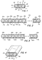
- a fiber optic micro cable 10 in accordance with the present invention includes a core 12 covered by a jacket 14.
- the core 12 is a buffered core which includes a pair of longitudinally extending strength members 17 (structural wires) on either side of an optical fiber 20.
- the strength members 17 and the optical fiber 20 are embedded in a buffer material 24.
- the strength members 17 and the optical fiber 20 are positioned in a common plane, thereby resulting in a generally flat or rectangular shaped cable structure.
- the strength members 17 are selected to provide tensile strength to the micro cable 10 and also provide crush protection to the optical fiber 20 contained within the cable 10.
- the strength members 17 may be manufactured of a solid metal wire, such as a steel wire or copper wire, or alternatively, the strength members may be stranded metal wires. Additionally, the strength members may be manufactured of high strength non-conductive materials such as fiberglass, reinforced plastic or other high strength dielectric materials.
- the optical fiber 20 may be of any suitable type known in the art including a central fiber coated by one or more layers of coating material. The optical fiber may be a single mode, multi-mode, dispersion shifted, etc. optical fiber, depending on the desired application of the optical fiber.
- the central fiber may be coated with one or more layers of coating material to thereby provide the desired mechanical characteristics of the optical fiber.
- the fiber may be coated with one or more layers of UV curable coating material to thereby preserve the structural strength and improve the handling qualities of the optical fiber.
- Hermetically coated fibers may be used if hydrogen protection is required.
- the buffer material 24 is a low modulus of elasticity material which provides the desired compression qualities to thereby distribute compressive forces within the micro cable 10 and minimize forces applied to the optical fiber 20.
- the buffer material may be a UV curable buffer material such as CABLELITE manufactured by DSM Desotech.
- the buffer material may be a thermoplastic polymer such as HYTREL manufactured by DuPont. It will be understood by those skilled in the art that a variety of buffer materials may be used with the fiber optic micro cable of the present invention, provided that the buffer material provides the desired qualities of having a low modulus of elasticity, and the buffer material provides good adhesion with the jacket material.
- the jacket material 14 is selected to be tough and abrasion resistant.
- the jacket 14 may be formed from high density polyethylene (HDPE).
- HDPE high density polyethylene
- other materials such as thermoplastic polymer, e.g., SURLYN manufactured by DuPont, or a UV curable coating, e.g., CABLELITE manufactured by DSM Desotech, may be used as the cable jacket with the cable of the invention.
- thermoplastic polymer e.g., SURLYN manufactured by DuPont
- a UV curable coating e.g., CABLELITE manufactured by DSM Desotech
- the jacket 14 is fabricated so that there is slightly more material in the region of the strength members such that the profile of the completed cable includes protrusions 26 (Figs. 1 and 4) in the cable jacket 14 in the area of the strength members 17.
- the extra jacket material in the region of the strength member helps to concentrate the crushing forces applied to the cable 10 directly to the strength members 17 and thus relieve some of the stress on the optical fibers 17 contained within the cable 10. This feature thereby increases the ability of the cable to withstand crushing forces applied to the exterior of the cable.
- the strength members 17 are sized to give the cable its required tensile strength. Additionally, the strength members 17 are selected to have a slightly larger diameter than the optical fibers so that crushing forces are first applied to the strength members 17 rather than the optical fibers to protect the optical fiber in the crush mode. For example the nominal diameter of the strength members 17 is approximately 0.40 mm while the nominal diameter of the coated optical fiber is approximately 0.25 mm. The overall dimensions of the cable 10 illustrated in Fig. 1 including a pair of strength members 17 and a single optical fiber 20 within the core 24 is approximately 1mm by 1.5mm.
- the micro cable of the present invention provides protection to an optical fiber contained therein in two different modes of crushing forces.
- the larger diameter of the strength members 17 causes the strength members 17, as opposed to the optical fiber 20, to absorb the crush forces applied to the cable 10.
- the increased thickness of jacketing material 26 in the area of the strength members 17 further helps concentrate the crushing forces on to the strength members. Any crushing forces that are applied to the core 12 are equally distributed throughout the core 12 by the low modulus of elasticity buffer material 24 such that local concentrations of crushing forces do not damage the optical fiber 20.
- the present invention provides a second mode of crush protection in the lateral direction. If crushing forces are applied to the short or round edges 30 of the cable 10, the cushioning effect of the buffer material 24 helps distribute these crushing forces throughout the core 12.
- An added advantage of the present invention is that the flat construction of the micro cable causes the cable to have a natural tendency to conform to the flat dimension of the cable when the cable is bent around obstacles. Therefore, the cable is naturally exposed to the stronger mode of crush protection by exposing the flat surface 27 of the cable to external crushing forces.
- the flat cable design also lends itself to easy storage of the cable on a spool because the naturally flat design of the invention packs more effectively than a round structure.
- the cable design of the invention allows a smaller bend radius than prior art micro cables, thereby allowing the use of cable bobbins (spools) with much smaller belly diameters. This features enables the user to achieve higher winding efficiency for a given size bobbin.
- the invention does not use stranded or nested wires around a central optical fiber, problems associated with limited bend radius of the cable are eliminated. Additionally, the straight lay of the invention simplifies splicing of the cable. The strength member 17 and fibers 20 can be easily spliced and the jacket 14 restored with a diameter close to the original un-spliced cable. Additionally, the tensile strength of the spliced cable will be near that of the original un-spliced cable.
- a second embodiment of the invention 10a includes a plurality of parallel running strength members 17a. Between each of the strength members 17a is positioned a single optical fiber 20a. As with the embodiment of Fig. 1, the strength members 17a and optical fibers 20a are embedded within a core 12a of buffer material 24a.
- the core 12a is coated with a protective jacket 14a (outer sheath).
- the jacket material is of an increased thickness 26a at least in the area of the end strength members.
- the jacket material 14 may be of an increased thickness 26a in all of the areas of the strength member 17a, as illustrated in Fig. 2, to thereby provide superior crush protection throughout the width of the cable 10a so that optical fibers 20a are not damaged when the cable is exposed to compressive or crushing forces.
- a third embodiment of the invention includes a plurality of optical fibers 20b positioned between a pair of strength members 17b.
- the number of optical fibers 20b positioned between the strength members 17b is selected to provide the superior crush protection qualities to the cable while also maximizing the optical fiber content within the cable.
- the strength members 17b and optical fibers 20b are included in a core 12b of buffer material 24b, and the core 12b is surrounded by a protective jacket 14b. Excess jacket material 26b is provided in the area of the strength member 17b. Additional strength member 17b may be positioned within the cable as necessary to preserve the superior crush resistant characteristics of the cable.
- optical fiber and strength members may be provided in a fiber optic micro cable manufactured in accordance with the invention.
- a cable may be provided having a plurality of optical fibers between pairs of strength members.
- two or more strength members may be provided on at least one side of each optical fiber.
- a plurality of strength members may be provided on at least one side of a plurality of optical fibers.
- the strength member 17, 17a, 17b may be an electronic signal transmission media, such as copper wires, for carrying electrical current to power devices, such as optical repeaters.
- the copper wire may be used to transmit electronic data and signaling.
- the buffer material 24, 24a, 24b and the jacket material 14, 14a, 14b is selected to provide proper insulation for the copper wires.
Landscapes
- Physics & Mathematics (AREA)
- General Physics & Mathematics (AREA)
- Optics & Photonics (AREA)
- Communication Cables (AREA)
- Light Guides In General And Applications Therefor (AREA)
Applications Claiming Priority (2)
| Application Number | Priority Date | Filing Date | Title |
|---|---|---|---|
| US08/585,085 US5673352A (en) | 1996-01-12 | 1996-01-12 | Fiber optic micro cable |
| US585085 | 1996-01-12 |
Publications (2)
| Publication Number | Publication Date |
|---|---|
| EP0784220A1 true EP0784220A1 (de) | 1997-07-16 |
| EP0784220B1 EP0784220B1 (de) | 2006-03-29 |
Family
ID=24339991
Family Applications (1)
| Application Number | Title | Priority Date | Filing Date |
|---|---|---|---|
| EP97400042A Expired - Lifetime EP0784220B1 (de) | 1996-01-12 | 1997-01-09 | Faseroptisches Miniaturkabel |
Country Status (4)
| Country | Link |
|---|---|
| US (1) | US5673352A (de) |
| EP (1) | EP0784220B1 (de) |
| JP (1) | JP3876936B2 (de) |
| DE (1) | DE69735579T2 (de) |
Cited By (12)
| Publication number | Priority date | Publication date | Assignee | Title |
|---|---|---|---|---|
| GB2336002A (en) * | 1998-02-17 | 1999-10-06 | Hubbell Inc | Composite ribbon cable |
| EP1152272A3 (de) * | 2000-05-03 | 2004-08-11 | Alcatel | Verstärktes gepuffertes faseroptisches Bandkabel |
| EP1312961A3 (de) * | 2001-11-14 | 2005-04-20 | Harris Corporation | Vorrichtung mit einem faseroptischen Kabelbaum und dazugehörige Verfahren |
| WO2006061370A1 (de) * | 2004-12-09 | 2006-06-15 | Siemens Aktiengesellschaft | Bandförmiger lichtleiter mit mehreren optischen einzelfasern und verfahren zu dessen herstellung |
| EP1840610A1 (de) * | 2006-03-30 | 2007-10-03 | Fujikura Ltd. | Verbindungsplatte für eine optische/elektrische Schaltung und Evaluierungsverfahren dafür |
| US7539380B1 (en) | 2007-11-26 | 2009-05-26 | Corning Cable Systems Llc | Fiber optic cables and assemblies for fiber toward the subscriber applications |
| WO2009070200A1 (en) * | 2007-11-26 | 2009-06-04 | Corning Cable Systems Llc | Fiber optic cables and assemblies for fiber toward the subscriber applications |
| WO2010039530A1 (en) * | 2008-09-23 | 2010-04-08 | Corning Cable Systems Llc | Fiber optic cables and assemblies for fiber toward the subscriber applications |
| EP2196834A1 (de) * | 2008-12-12 | 2010-06-16 | Draka Comteq B.V. | Gepufferte optische Faser, Telekommunikationskabel mit optischen Fasern und Verfahren zur Herstellung derartiger Faser |
| US7983520B2 (en) | 2007-06-26 | 2011-07-19 | Corning Cable Systems Llc | Methods of making optical fiber assemblies having relatively low-levels of water-swellable powder |
| US8180190B2 (en) | 2008-07-31 | 2012-05-15 | Corning Cable Systems Llc | Optical fiber assemblies having a powder or powder blend at least partially mechanically attached |
| US9417421B2 (en) | 2008-08-15 | 2016-08-16 | Corning Cable Systems Llc | Optical fiber assemblies, and methods and apparatus for the manufacture thereof |
Families Citing this family (37)
| Publication number | Priority date | Publication date | Assignee | Title |
|---|---|---|---|---|
| US6107577A (en) * | 1995-06-05 | 2000-08-22 | Sexton; Robert Jay | Flat surface-mounted multi-purpose wire |
| US6195489B1 (en) * | 1997-01-31 | 2001-02-27 | Fujikura Ltd. | Optical fiber cord, ribbon cord using the same and ribbon cord branch line |
| US6160940A (en) * | 1997-06-05 | 2000-12-12 | Corning Cable Systems Llc | Fiber optic cable for installation in a cable passageway and methods and an apparatus for producing the same |
| US6492595B2 (en) | 1997-10-01 | 2002-12-10 | Decorp Americas, Inc. | Flat surface-mounted multi-purpose wire |
| US6151336A (en) | 1998-02-11 | 2000-11-21 | Sorrento Networks, Inc. | Time division multiplexing expansion subsystem |
| US6400478B1 (en) | 1998-04-02 | 2002-06-04 | Sorrento Networks, Inc. | Wavelength-division-multiplexed optical transmission system with expanded bidirectional transmission capacity over a single fiber |
| US6097866A (en) * | 1998-05-01 | 2000-08-01 | Alcatel | Optical fiber ribbon |
| US6298103B1 (en) | 1998-06-16 | 2001-10-02 | Sorrento Networks Corporation | Flexible clock and data recovery module for a DWDM optical communication system with multiple clock rates |
| DE19852572A1 (de) * | 1998-11-13 | 2000-05-31 | Siemens Ag | Kabelnetz mit Lichtwellenleiterkabeln für die Installation in Rohrleitungen bestehender Versorgungsleitungssysteme |
| US6363192B1 (en) * | 1998-12-23 | 2002-03-26 | Corning Cable Systems Llc | Composite cable units |
| US6493491B1 (en) | 1999-09-28 | 2002-12-10 | Alcatel | Optical drop cable for aerial installation |
| US6577797B2 (en) * | 2001-05-09 | 2003-06-10 | Hon Hai Precision Ind. Co., Ltd. | Optical fiber ribbon assembly with strain relief |
| DE10140310A1 (de) * | 2001-08-16 | 2003-02-27 | Ccs Technology Inc | Laschband |
| US6792184B2 (en) * | 2002-05-31 | 2004-09-14 | Corning Cable Systems Llc | Optical fiber ribbons having a preferential separation sequence |
| US6748148B2 (en) | 2002-05-31 | 2004-06-08 | Corning Cable Systems Llc | Optical fiber ribbons having a non-uniform thickness and/or preferential tear portions |
| KR20040052408A (ko) * | 2002-12-17 | 2004-06-23 | 삼성전자주식회사 | 인장재를 포함하는 리본 광섬유 |
| US7415181B2 (en) * | 2005-07-29 | 2008-08-19 | Corning Cable Systems Llc | Fiber optic cables and assemblies for fiber to the subscriber applications |
| US7471862B2 (en) | 2002-12-19 | 2008-12-30 | Corning Cable Systems, Llc | Dry fiber optic cables and assemblies |
| US6853783B2 (en) | 2003-02-28 | 2005-02-08 | Corning Cable Systems Llc | Optical Fiber Ribbons Having Preferential Tear Portions |
| US7737359B2 (en) * | 2003-09-05 | 2010-06-15 | Newire Inc. | Electrical wire and method of fabricating the electrical wire |
| US7145073B2 (en) | 2003-09-05 | 2006-12-05 | Southwire Company | Electrical wire and method of fabricating the electrical wire |
| US7217884B2 (en) | 2004-03-02 | 2007-05-15 | Southwire Company | Electrical wire and method of fabricating the electrical wire |
| US20050244159A1 (en) * | 2004-04-30 | 2005-11-03 | Aref Chowdhury | Optical wavelength-conversion |
| US7039282B2 (en) * | 2004-06-30 | 2006-05-02 | Corning Cable Systems Llc | Optical fiber array with an intermittent profile and method for manufacturing the same |
| US7194168B2 (en) * | 2005-03-03 | 2007-03-20 | Nexans | Tight buffer optical fiber ribbon |
| JP2008076427A (ja) * | 2006-09-19 | 2008-04-03 | Tomoegawa Paper Co Ltd | 光ファイバ集合体 |
| US7532796B2 (en) * | 2006-09-29 | 2009-05-12 | Corning Cable Systems Llc | Fiber optic ribbons having one or more predetermined fracture regions |
| US7274846B1 (en) | 2006-09-29 | 2007-09-25 | Corning Cable Systems, Llc. | Fiber optic ribbon subunits having ends with different shapes |
| FR2938080B1 (fr) * | 2008-11-06 | 2011-03-11 | Acome Soc Coop Production | Cable a fibre optique pour le transport de donnees, notamment dans un reseau local domestique |
| WO2013016135A2 (en) | 2011-07-22 | 2013-01-31 | Adc Telecommunications, Inc. | Fiber optic connector and cable assembly having a fiber locking mechanism |
| WO2013059315A1 (en) * | 2011-10-17 | 2013-04-25 | Schlumberger Canada Limited | Dual use cable with fiber optic packaging for use in wellbore operations |
| GB2518774B (en) | 2012-06-28 | 2020-01-29 | Schlumberger Holdings | High power opto-electrical cable with multiple power and telemetry paths |
| CN103823284B (zh) * | 2014-03-09 | 2016-04-27 | 北京亨通斯博通讯科技有限公司 | 一种路面微槽光缆 |
| US11725468B2 (en) | 2015-01-26 | 2023-08-15 | Schlumberger Technology Corporation | Electrically conductive fiber optic slickline for coiled tubing operations |
| CA2994387A1 (en) * | 2015-07-31 | 2017-02-09 | Corning Optical Communications LLC | Rollable optical fiber ribbon |
| US10049789B2 (en) | 2016-06-09 | 2018-08-14 | Schlumberger Technology Corporation | Compression and stretch resistant components and cables for oilfield applications |
| US10739169B2 (en) * | 2017-03-23 | 2020-08-11 | Ofs Fitel, Llc | Flat profile optical fiber cable for distributed sensing applications |
Citations (7)
| Publication number | Priority date | Publication date | Assignee | Title |
|---|---|---|---|---|
| US3887265A (en) * | 1972-11-10 | 1975-06-03 | British Insulated Callenders | Optical guides |
| FR2387460A2 (fr) * | 1977-04-13 | 1978-11-10 | Bicc Ltd | Cable pour les guides optiques |
| DE3131424A1 (de) * | 1981-08-07 | 1983-02-24 | Siemens AG, 1000 Berlin und 8000 München | Optisches uebertragungselement mit zwei zugfesten tragorganen |
| US4761053A (en) * | 1985-08-28 | 1988-08-02 | American Telephone And Telegraph Company, At&T Bell Laboratories | Communications transmission media |
| EP0468689A1 (de) * | 1990-07-25 | 1992-01-29 | AT&T Corp. | Zubringer-Luftkabel |
| US5259055A (en) | 1988-05-23 | 1993-11-02 | The United States Of America As Represented By The Secrtary Of The Navy | Fiber optic microcable produced with radiation cured composite |
| US5440660A (en) | 1988-05-23 | 1995-08-08 | The United States Of America As Represented By The Secretary Of Navy | Fiber optic microcable produced with fiber reinforced ultraviolet light cured resin and method for manufacturing same |
Family Cites Families (9)
| Publication number | Priority date | Publication date | Assignee | Title |
|---|---|---|---|---|
| US4190319A (en) * | 1978-02-13 | 1980-02-26 | Essex Group, Inc. | Fiber optic ribbon and cable made therefrom |
| JPS6086515A (ja) * | 1983-10-18 | 1985-05-16 | Junkosha Co Ltd | 光伝送条体及びこれを用いたフラツトケ−ブル |
| JP2776496B2 (ja) * | 1984-07-09 | 1998-07-16 | セコム 株式会社 | 電気錠装置 |
| JPS6127514A (ja) * | 1984-07-19 | 1986-02-07 | Daiichi Denko Kk | 平型光フアイバケ−ブル |
| GB8423311D0 (en) * | 1984-09-14 | 1984-10-17 | Telephone Cables Ltd | Optical fibre cables |
| US4815814A (en) * | 1986-09-02 | 1989-03-28 | Cooper Industries, Inc. | Under-carpet flat cable assembly and method of forming a turn in same |
| DE3709170A1 (de) * | 1987-03-20 | 1988-09-29 | Standard Elektrik Lorenz Ag | Optisches kabelelement und optisches kabel |
| JPH01200310A (ja) * | 1988-02-05 | 1989-08-11 | Sumitomo Electric Ind Ltd | 偏平クラツド定偏波フアイバの被覆方法 |
| US4900126A (en) * | 1988-06-30 | 1990-02-13 | American Telephone & Telegraph Co. | Bonded array of transmission media |
-
1996
- 1996-01-12 US US08/585,085 patent/US5673352A/en not_active Expired - Lifetime
-
1997
- 1997-01-09 DE DE69735579T patent/DE69735579T2/de not_active Expired - Fee Related
- 1997-01-09 EP EP97400042A patent/EP0784220B1/de not_active Expired - Lifetime
- 1997-01-10 JP JP00304597A patent/JP3876936B2/ja not_active Expired - Fee Related
Patent Citations (7)
| Publication number | Priority date | Publication date | Assignee | Title |
|---|---|---|---|---|
| US3887265A (en) * | 1972-11-10 | 1975-06-03 | British Insulated Callenders | Optical guides |
| FR2387460A2 (fr) * | 1977-04-13 | 1978-11-10 | Bicc Ltd | Cable pour les guides optiques |
| DE3131424A1 (de) * | 1981-08-07 | 1983-02-24 | Siemens AG, 1000 Berlin und 8000 München | Optisches uebertragungselement mit zwei zugfesten tragorganen |
| US4761053A (en) * | 1985-08-28 | 1988-08-02 | American Telephone And Telegraph Company, At&T Bell Laboratories | Communications transmission media |
| US5259055A (en) | 1988-05-23 | 1993-11-02 | The United States Of America As Represented By The Secrtary Of The Navy | Fiber optic microcable produced with radiation cured composite |
| US5440660A (en) | 1988-05-23 | 1995-08-08 | The United States Of America As Represented By The Secretary Of Navy | Fiber optic microcable produced with fiber reinforced ultraviolet light cured resin and method for manufacturing same |
| EP0468689A1 (de) * | 1990-07-25 | 1992-01-29 | AT&T Corp. | Zubringer-Luftkabel |
Cited By (29)
| Publication number | Priority date | Publication date | Assignee | Title |
|---|---|---|---|---|
| GB2336002A (en) * | 1998-02-17 | 1999-10-06 | Hubbell Inc | Composite ribbon cable |
| EP1152272A3 (de) * | 2000-05-03 | 2004-08-11 | Alcatel | Verstärktes gepuffertes faseroptisches Bandkabel |
| EP1312961A3 (de) * | 2001-11-14 | 2005-04-20 | Harris Corporation | Vorrichtung mit einem faseroptischen Kabelbaum und dazugehörige Verfahren |
| WO2006061370A1 (de) * | 2004-12-09 | 2006-06-15 | Siemens Aktiengesellschaft | Bandförmiger lichtleiter mit mehreren optischen einzelfasern und verfahren zu dessen herstellung |
| EP1840610A1 (de) * | 2006-03-30 | 2007-10-03 | Fujikura Ltd. | Verbindungsplatte für eine optische/elektrische Schaltung und Evaluierungsverfahren dafür |
| US7983520B2 (en) | 2007-06-26 | 2011-07-19 | Corning Cable Systems Llc | Methods of making optical fiber assemblies having relatively low-levels of water-swellable powder |
| CN101925841A (zh) * | 2007-11-26 | 2010-12-22 | 康宁光缆系统有限公司 | 用于光纤到用户应用的光缆及组件 |
| US7539380B1 (en) | 2007-11-26 | 2009-05-26 | Corning Cable Systems Llc | Fiber optic cables and assemblies for fiber toward the subscriber applications |
| AU2008309134B2 (en) * | 2007-11-26 | 2010-02-25 | Corning Cable Systems Llc | Fiber optic cables and assemlies for fiber toward the subscriber applications |
| AU2008309134B8 (en) * | 2007-11-26 | 2010-03-25 | Corning Cable Systems Llc | Fiber optic cables and assemlies for fiber toward the subscriber applications |
| CN101925841B (zh) * | 2007-11-26 | 2014-11-19 | 康宁光缆系统有限公司 | 用于光纤到用户应用的光缆及组件 |
| US7567741B2 (en) | 2007-11-26 | 2009-07-28 | Corning Cable Systems Llc | Fiber optic cables and assemblies for fiber toward the subscriber applications |
| AU2010201456B2 (en) * | 2007-11-26 | 2012-12-06 | Corning Cable Systems Llc | Fiber optic cables and assemblies for fiber toward the subscriber applications |
| US7796853B2 (en) | 2007-11-26 | 2010-09-14 | Corning Cable Systems Llc | Fiber optic cables and assemblies for fiber toward the subscriber applications |
| WO2009070200A1 (en) * | 2007-11-26 | 2009-06-04 | Corning Cable Systems Llc | Fiber optic cables and assemblies for fiber toward the subscriber applications |
| US8750661B2 (en) | 2008-07-31 | 2014-06-10 | Corning Cable Systems Llc | Optical fiber assemblies having a powder or powder blend at least partially mechanically attached |
| US8542966B2 (en) | 2008-07-31 | 2013-09-24 | Corning Cable Systems Llc | Optical fiber assemblies having a powder or powder blend at least partially mechanically attached |
| US8989542B2 (en) | 2008-07-31 | 2015-03-24 | Corning Optical Communications LLC | Optical fiber assemblies having a powder or powder blend at least partially mechanically attached |
| US8180190B2 (en) | 2008-07-31 | 2012-05-15 | Corning Cable Systems Llc | Optical fiber assemblies having a powder or powder blend at least partially mechanically attached |
| US9417421B2 (en) | 2008-08-15 | 2016-08-16 | Corning Cable Systems Llc | Optical fiber assemblies, and methods and apparatus for the manufacture thereof |
| US8538216B2 (en) | 2008-09-23 | 2013-09-17 | Corning Cable Systems Llc | Fiber optic cables and assemblies for fiber toward the subscriber applications |
| US8712200B1 (en) | 2008-09-23 | 2014-04-29 | Corning Cable Systems Llc | Fiber optic cables and assemblies for fiber toward the subscriber applications |
| WO2010039530A1 (en) * | 2008-09-23 | 2010-04-08 | Corning Cable Systems Llc | Fiber optic cables and assemblies for fiber toward the subscriber applications |
| US9477056B2 (en) | 2008-09-23 | 2016-10-25 | Corning Optical Communications LLC | Fiber optic cables and assemblies for fiber toward the subscriber applications |
| US9989722B2 (en) | 2008-09-23 | 2018-06-05 | Corning Optical Communications LLC | Fiber optic cables and assemblies for fiber toward the subscriber applications |
| US10684432B2 (en) | 2008-09-23 | 2020-06-16 | Corning Optical Communications LLC | Fiber optic cables and assemblies for fiber toward the subscriber applications |
| EP2196834A1 (de) * | 2008-12-12 | 2010-06-16 | Draka Comteq B.V. | Gepufferte optische Faser, Telekommunikationskabel mit optischen Fasern und Verfahren zur Herstellung derartiger Faser |
| US8346040B2 (en) | 2008-12-12 | 2013-01-01 | Draka Comteq, B.V. | Buffered optical fiber |
| FR2939911A1 (fr) * | 2008-12-12 | 2010-06-18 | Draka Comteq France | Fibre optique gainee, cable de telecommunication comportant plusieurs fibres optiques et procede de fabrication d'une telle fibre |
Also Published As
| Publication number | Publication date |
|---|---|
| JPH09218329A (ja) | 1997-08-19 |
| US5673352A (en) | 1997-09-30 |
| DE69735579T2 (de) | 2007-02-08 |
| EP0784220B1 (de) | 2006-03-29 |
| JP3876936B2 (ja) | 2007-02-07 |
| DE69735579D1 (de) | 2006-05-18 |
Similar Documents
| Publication | Publication Date | Title |
|---|---|---|
| US5673352A (en) | Fiber optic micro cable | |
| EP1319195B1 (de) | Glasfaserkabel mit verstärkungselementen | |
| US5740295A (en) | Low fiber count optical cable | |
| CA2359753C (en) | Optical fiber cable with support member for indoor and outdoor use | |
| EP0893722B1 (de) | Faseroptischeskombinationskabel | |
| EP1591814B1 (de) | Glasfaserkabel mit hoher Faserzahl | |
| CA2042165C (en) | Composite cable | |
| EP1203254B1 (de) | Faseroptisches kabel mit verstärkungselement innerhalb einer äusseren umhüllung | |
| EP0459415B1 (de) | Optisches Kabel und Verfahren zu seiner Herstellung | |
| CA2324089C (en) | High fiber count, compact, loose tube optical fiber cable employing ribbon units and flexible buffer tubes | |
| US4312566A (en) | Dielectric optical waveguide cables | |
| KR20080027328A (ko) | 광섬유 케이블 및 그 제조방법 | |
| US6421487B1 (en) | Reinforced buffered fiber optic ribbon cable | |
| IE52815B1 (en) | Optical fibre cable | |
| US5960144A (en) | Communication cable with strain relief elements applied in the region of the outside cladding | |
| CA2005114C (en) | All-dielectric optical fiber cable having enhanced fiber access | |
| JPH0926535A (ja) | スロット付小型コアリボンケーブル | |
| KR102941747B1 (ko) | 광케이블 | |
| GB2036361A (en) | Reinforced Optical Fiber Conductor and Optical Fiber Cable Incorporating such Conductors | |
| US20190113703A1 (en) | Fiber Optic Drop Cable | |
| GB2215480A (en) | Optical fibre cable element | |
| EP4239386B1 (de) | Faseroptisches kabel mit länglichen verstärkungselementen und herstellungsverfahren dafür | |
| KR102955532B1 (ko) | 광케이블 | |
| KR20000046917A (ko) | 고강도 광섬유 케이블 | |
| US20230251444A1 (en) | Aerial drop optical fibre cable |
Legal Events
| Date | Code | Title | Description |
|---|---|---|---|
| PUAI | Public reference made under article 153(3) epc to a published international application that has entered the european phase |
Free format text: ORIGINAL CODE: 0009012 |
|
| AK | Designated contracting states |
Kind code of ref document: A1 Designated state(s): DE FR GB IT |
|
| 17P | Request for examination filed |
Effective date: 19980116 |
|
| RAP3 | Party data changed (applicant data changed or rights of an application transferred) |
Owner name: ALCATEL |
|
| RAP3 | Party data changed (applicant data changed or rights of an application transferred) |
Owner name: ALCATEL |
|
| 17Q | First examination report despatched |
Effective date: 20030723 |
|
| GRAP | Despatch of communication of intention to grant a patent |
Free format text: ORIGINAL CODE: EPIDOSNIGR1 |
|
| RAP1 | Party data changed (applicant data changed or rights of an application transferred) |
Owner name: DRAKA COMTEQ B.V. |
|
| GRAS | Grant fee paid |
Free format text: ORIGINAL CODE: EPIDOSNIGR3 |
|
| GRAA | (expected) grant |
Free format text: ORIGINAL CODE: 0009210 |
|
| AK | Designated contracting states |
Kind code of ref document: B1 Designated state(s): DE FR GB IT |
|
| PG25 | Lapsed in a contracting state [announced via postgrant information from national office to epo] |
Ref country code: IT Free format text: LAPSE BECAUSE OF FAILURE TO SUBMIT A TRANSLATION OF THE DESCRIPTION OR TO PAY THE FEE WITHIN THE PRESCRIBED TIME-LIMIT;WARNING: LAPSES OF ITALIAN PATENTS WITH EFFECTIVE DATE BEFORE 2007 MAY HAVE OCCURRED AT ANY TIME BEFORE 2007. THE CORRECT EFFECTIVE DATE MAY BE DIFFERENT FROM THE ONE RECORDED. Effective date: 20060329 |
|
| REG | Reference to a national code |
Ref country code: GB Ref legal event code: FG4D |
|
| REF | Corresponds to: |
Ref document number: 69735579 Country of ref document: DE Date of ref document: 20060518 Kind code of ref document: P |
|
| ET | Fr: translation filed | ||
| PLBE | No opposition filed within time limit |
Free format text: ORIGINAL CODE: 0009261 |
|
| STAA | Information on the status of an ep patent application or granted ep patent |
Free format text: STATUS: NO OPPOSITION FILED WITHIN TIME LIMIT |
|
| 26N | No opposition filed |
Effective date: 20070102 |
|
| PGFP | Annual fee paid to national office [announced via postgrant information from national office to epo] |
Ref country code: DE Payment date: 20090122 Year of fee payment: 13 |
|
| PGFP | Annual fee paid to national office [announced via postgrant information from national office to epo] |
Ref country code: GB Payment date: 20090122 Year of fee payment: 13 |
|
| PGFP | Annual fee paid to national office [announced via postgrant information from national office to epo] |
Ref country code: IT Payment date: 20090128 Year of fee payment: 13 |
|
| PGFP | Annual fee paid to national office [announced via postgrant information from national office to epo] |
Ref country code: FR Payment date: 20090115 Year of fee payment: 13 |
|
| GBPC | Gb: european patent ceased through non-payment of renewal fee |
Effective date: 20100109 |
|
| REG | Reference to a national code |
Ref country code: FR Ref legal event code: ST Effective date: 20100930 |
|
| PG25 | Lapsed in a contracting state [announced via postgrant information from national office to epo] |
Ref country code: FR Free format text: LAPSE BECAUSE OF NON-PAYMENT OF DUE FEES Effective date: 20100201 |
|
| PG25 | Lapsed in a contracting state [announced via postgrant information from national office to epo] |
Ref country code: DE Free format text: LAPSE BECAUSE OF NON-PAYMENT OF DUE FEES Effective date: 20100803 |
|
| PG25 | Lapsed in a contracting state [announced via postgrant information from national office to epo] |
Ref country code: GB Free format text: LAPSE BECAUSE OF NON-PAYMENT OF DUE FEES Effective date: 20100109 |
|
| PG25 | Lapsed in a contracting state [announced via postgrant information from national office to epo] |
Ref country code: IT Free format text: LAPSE BECAUSE OF NON-PAYMENT OF DUE FEES Effective date: 20100109 |