EP0785542A1 - Unité de disque magnétique - Google Patents
Unité de disque magnétique Download PDFInfo
- Publication number
- EP0785542A1 EP0785542A1 EP97300191A EP97300191A EP0785542A1 EP 0785542 A1 EP0785542 A1 EP 0785542A1 EP 97300191 A EP97300191 A EP 97300191A EP 97300191 A EP97300191 A EP 97300191A EP 0785542 A1 EP0785542 A1 EP 0785542A1
- Authority
- EP
- European Patent Office
- Prior art keywords
- signal
- head
- positional
- disk drive
- magnetic disk
- Prior art date
- Legal status (The legal status is an assumption and is not a legal conclusion. Google has not performed a legal analysis and makes no representation as to the accuracy of the status listed.)
- Granted
Links
- 238000005070 sampling Methods 0.000 claims abstract description 7
- 238000000034 method Methods 0.000 claims description 14
- 230000014509 gene expression Effects 0.000 claims description 9
- 230000003252 repetitive effect Effects 0.000 claims description 5
- 239000006185 dispersion Substances 0.000 claims 1
- 230000006698 induction Effects 0.000 claims 1
- 238000010586 diagram Methods 0.000 description 13
- 101000860173 Myxococcus xanthus C-factor Proteins 0.000 description 3
- 230000035945 sensitivity Effects 0.000 description 3
- 230000000694 effects Effects 0.000 description 2
- 238000005259 measurement Methods 0.000 description 2
- 230000007423 decrease Effects 0.000 description 1
- 238000001514 detection method Methods 0.000 description 1
- 238000004519 manufacturing process Methods 0.000 description 1
Images


Classifications
-
- G—PHYSICS
- G11—INFORMATION STORAGE
- G11B—INFORMATION STORAGE BASED ON RELATIVE MOVEMENT BETWEEN RECORD CARRIER AND TRANSDUCER
- G11B5/00—Recording by magnetisation or demagnetisation of a record carrier; Reproducing by magnetic means; Record carriers therefor
- G11B5/48—Disposition or mounting of heads or head supports relative to record carriers ; arrangements of heads, e.g. for scanning the record carrier to increase the relative speed
- G11B5/58—Disposition or mounting of heads or head supports relative to record carriers ; arrangements of heads, e.g. for scanning the record carrier to increase the relative speed with provision for moving the head for the purpose of maintaining alignment of the head relative to the record carrier during transducing operation, e.g. to compensate for surface irregularities of the latter or for track following
- G11B5/596—Disposition or mounting of heads or head supports relative to record carriers ; arrangements of heads, e.g. for scanning the record carrier to increase the relative speed with provision for moving the head for the purpose of maintaining alignment of the head relative to the record carrier during transducing operation, e.g. to compensate for surface irregularities of the latter or for track following for track following on disks
- G11B5/59633—Servo formatting
- G11B5/59655—Sector, sample or burst servo format
Definitions
- the present invention relates to head position detection of a magnetic disk drive, and more particularly to a magnetic disk drive capable of positioning the head in accordance with a linear positional signal relative to the position obtained by switching signals that are obtained by demodulating a multi-phase servo pattern of two phases or more.
- one inductive-type magnetic head was used for read and write operations.
- an MR (magneto-resistive) head using magneto-resistance effect is beginning to be employed for this purpose. Since the MR head is dedicated only to read operation, it is generally combined with an inductive-type magnetic head for writing to form a read/write separate head.
- Fig. 7 is a plan view of one example of a read/write separate head 9 formed by a MR read head and a magnetic write head.
- a read gap 90 for reading information and a write gap 92 for writing information are formed, each of which extends to cross each data track widthwise.
- the read gap 90 has its length made shorter than the write gap 92, and its center relative to its length is deviated with respect to the center of the write gap 92. The amount of this deviation is indicated by d in Fig. 7.
- the magnetic head 9 includes a read element (not shown) provided for the read gap 90 for reading information by use of an MR element, and a write element (not shown) provided for the write gap 92 for writing information by use of a coil.
- the head 9 is mounted on the tip of a head support system (arm) and is held at a position somewhat spaced from the record surface of the magnetic disk.
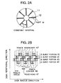
- Figs. 2A and 2B show one example of the positional information recorded on the disk.
- Fig. 2A is a schematic diagram of a disk surface of sector servo system
- Fig. 2B is a schematic diagram of a positional information recorded region, or a magnification of a part M in Fig. 2A.
- the positional information is usually formed by a repetition pattern of an A burst portion 42, a B burst portion 43, a C burst portion 44 and a D burst portion 45.
- Fig. 3A illustrates a relation between the head position and the N, Q signal.
- the N signal has a waveform with smooth peaks at around maxima as shown in Fig. 3A. Since the C burst and D burst are recorded deviated by 1/2 track pitch in the radius direction of the disk from the A burst and B burst as illustrated in Fig. 2B, the Q signal corresponds to the N signal parallelly moved by 1/2 track pitch in the direction of the head position.
- the absolute value of N signal is compared with that of Q signal, and the smaller one is selected.
- the sign is inverted as the need arises in order that the selected signals become straight lines increasing to the right, or that Ni signals and Qi signals can be produced (Fig. 3B).
- the point where the absolute value of the N signal equals that of the Q signal constitutes a switching point of the positional signal.
- the Qi signals within the track pitch as shown in Fig. 3B are offset by 2Vo or -2Vo so that the positional signal increases as the head moves within the track pitch and that the Qi, Ni signals can be connected to form a Qc signal 51 as the positional signal as shown in Fig. 3C.
- the head position was specified by the positional signal produced by the above method, and the head was controlled to be positioned in accordance with the positional signal.
- the read head position (point W) at data writing must be shifted from the read head position (point R) at data reading.
- Fig. 4A shows a switching between the N, Q signals and a relation between the head position and the positional signal
- Fig. 4B shows the positional signal at around the phase-switching point.
- point R is much separated from point W
- the head is required to be positioned at around the switching point (point CH).
- point R is beyond the switching point CH
- the Q signal is inverted and twice the design value at the intersection between N signal and Q signal, or 2Vo is added to the inverted Q signal to produce the positional signal Qc 51.
- the voltage (Vch) at the intersection between N signal and Q signal sometimes does not coincide with the design value (Vo) because of the variation of the head output.
- the voltage Vch is not always constant at each sector because of the variation of the track pitch.
- the track pitch variation means that when positional information is written on the disk by the servo track writer, the track center 46 and the track boundary line 47 become vibratory because of the vibration of the disk apparatus or the like with the result that a perfectly constant track pitch cannot be obtained at each sector even within the same track.
- the amount of parallel movement of Q signal away from N signal is not 1/2 track pitch as designed.
- the voltage (Vch) at the intersection between N signal and Q signal does not coincide with the design value (Vo).
- Fig. 4B shows the positional signal at around the switching point (magnified view of part P in Fig. 4A).
- Vo ⁇ Vch as illustrated, the positional signal is discontinuous at the switching point (point CH) between the N signal and Q signal, and thus the head positioning precision is lowered at around the switching point CH, to a problem.
- JP-A-7-45020 it is disclosed that for the purpose of removing the unnatural variable point of the positional signal, when the positional signal is produced by directly using the A, B, C and D signals reproduced from the A, B, C and D bursts in place of the N signal and Q signal, the amount that the signal reproduced from the head is offset is detected, which amount is varied by the change of the voltages applied to the head and amplifier or by the change of ambient temperature.
- This method does not consider the discontinuity of the positional signal due to the variation of the track pitch.
- the problem with the offset for the reproduced signal output level vertical direction
- discontinuity still occurs when the reproduced signal waveform is shifted in the disk-radius direction (lateral or right-left direction) due to the track pitch variation.
- the track pitch is not constant even within the same track since the disk apparatus is vibrating when positional information is recorded on the disk by a device generally called servo track writer. Therefore, as long as the relation between the voltage and the track pitch is kept constant, continuity is not assured at the switching point in the positional signal produced by phase-switching.
- a preferred aim of the invention is to provide a magnetic disk drive wherein it is assured that a positional signal is continuous at all positions in the radius direction on the disk, including the switching points, even when multi-phase signals are switched, and precisely positioning the head at an arbitrary point on a track.
- Another preferred aim of the invention is to automatically adjust the servo gain by normalizing the positional signal by the voltage at the switching point without regard to the head position.
- Yet another preferred aim of the invention is to calculate the positional signal in order to compensate the nonlinearility of the N signal and Q signal due to the reproduction sensitivity distribution of the MR head.
- the disk drive has a function added thereto of compensating the values of N signal and Q signal at each sampling time so that the positional signal is normalized by the voltage at the intersection between the N signal and Q signal at all points in the radius direction on the disk.
- Q' signal Q signal / (
- N signal Q signal
- Q signal Q signal / (
- N signal Q signal
- the calculated results of Eqs. (1) and (2), or N', Q' signals are 1/ ⁇ 2 (a predetermined value).
- the amount of the offset for the switching point is made 2/ ⁇ 2 by using N' signal and Q' signal, the continuous positional signal is always produced.
- the servo gain can also be automatically adjusted at the same time.
- the disk drive when Eqs. (1) and (2) are executed by substituting approximate expressions using Taylor expansion formula or Taylor series, the disk drive is provided with a function of compensating the nonlinearity of N signal and Q signal due to the reproduction sensitivity distribution of MR head by changing the Taylor expansion coefficients.
- Fig. 1 is a schematic diagram of a magnetic disk drive of an embodiment of the invention.
- Figs. 2A and 2B are respectively a diagram showing positional information recorded regions on the disk surface, and a diagram showing a burst pattern recorded on the disk.
- Figs. 3A, 3B and 3C are respectively a diagram showing a relation between the head position and the N, Q signals, a diagram showing selection and inversion of N signal and Q signal, and a diagram showing a way of connecting sections of Ni and Qc signals to produce the positional signal.
- Figs. 4A, 4B and 4C are respectively a diagram showing switching between signals of different phases for the positional signal and a relation between the head position and the positional signal, a diagram showing the neighborhood of a switching point between N, Q signals, and a diagram showing the neighborhood of the switching point between N', Q' signals according to the invention.
- Fig. 5 is a diagram showing a track pitch variation.
- Figs. 6A and 6B are respectively a graph showing the measurements of the positional signal in a disk drive according to the invention, and a graph showing the measurements of the positional signal in a conventional disk drive.
- Fig. 7 is a plan view of the structure of a read/write separate head.
- FIG. 1 is a block diagram of the arrangement of the positioning control system of a magnetic disk drive of sector servo system using a two-phase servo signal according to the invention.
- a command for writing or reading is transmitted from a central processing unit 1 (CPU) to a disk controller 2
- the disk controller 2 supplies to a microprocessor 3 a command for instructing it to position a head 9 at a specific point.
- the signal for positioning the head 9 is produced from a signal that is reproduced by the head 9 from a positional information recorded region 12.
- the positional information has such a pattern as shown in Fig. 2B.
- Each signal produced when the head 9 crosses the A burst portion 42, B burst portion 43, C burst portion 44 and D burst portion 45 is supplied through a read/write (R/W) integrated circuit (IC) 15, an automatic gain control (AGC) amplifier 16 and a full-wave rectifying circuit 18 to peak hold (P/H) circuits 19-22, which then respectively produce an A signal 23, a B signal 24, a C signal 25 and a D signal 26.
- R/W read/write
- AGC automatic gain control
- P/H peak hold
- the N signal 27 and Q signal 28 are supplied through an A/D converter 29 to the microprocessor 3 in which a compensation equation calculator 30 computes new N' signal and Q' signal according to Eqs. (1) and (2).
- a positional signal linearizer 31 combines or connect the N' signal and Q' signal together to form a positional signal which is linear with respect to the head position and which specifies the head position.
- the positional information is previously recorded at constant intervals on a disk 11 as shown in Fig. 2A.
- the head 9 sequentially crosses the A, B, C and D burst portions 42, 43, 44 and 45 in the positional information recorded region 12, the A, B, C and D signals 23, 24, 25 and 26 as shown in Fig.
- a positional control compensation filter 32 for lead-lag compensation is used to calculate and produce a manipulated variable from a positional error between the current head position and the target position so that the positional error can be reduced to zero.
- the manipulated variable is converted into an analog signal by a D/A converter 4, and then supplied to a VCM drive circuit 5 for driving a voice coil motor 6, which controls a head supporting arm 8 to position the head 9.
- Fig. 4C shows the positional signal at around the switching point which is produced according to the method of the invention (magnified view of part P in Fig. 4A).
- Fig. 6A shows the experimental results measured when the head 9 is positioned at around the switching point (point CH) according to the method of the invention
- Fig. 6B the results obtained according to a prior art.
- the abscissa represents time
- the ordinate represents the waveform of the positional signal of 1000 cycles. According to the invention, it will be seen from the waveform that the head 9 can be precisely positioned even at around the switching point (point CH).
- the present invention proposes the method for normalizing the gain and for making the positional signal always continuous at the phase-switching point in the magnetic disk drive of the multiphase servo signal switching control system.
- N' signal N signal/(
- Q' signal Q signal/(
- N signal 27 and Q signal 28 are produced by use of operational amplifiers
- the N signal 27 and Q signal 28 may be produced by converting the reproduced analog A, B, C and D signals 23, 24, 25 and 26 from the burst portions into digital signals and by processing them by the microprocessor 3.
- Q signal (C signal-D signal)/(
- the switching point is the intersection between the N signal 27 and the Q signal 28, or the point at which the N signal 27 equals the Q signal 28, the switching point is, in general, a point where the absolute value of the N signal 27 equals that of the Q signal 28 and inversion process and offset process are made as necessity requires in order to connect the N signal 27 and Q signal 28.
- Eqs. (1) and (2) are executed by the microprocessor 3, they are approximately calculated because the square root of a value is difficult to calculate.
- N signal and Q signal will hereinafter be represented by N and Q, respectively.
- the positional signal can be kept continuous even at the points where the N signal and Q signal are switched, and thus the head can be positioned precisely at an arbitrary point in the radius direction.
- the linearity of the positional signal can be improved by adjusting the parameters in the equations for the positional signal, and thus the head can be positioned precisely at an arbitrary point in the radius direction.
- the head can be precisely positioned at an arbitrary point in the radius direction.
Landscapes
- Moving Of The Head To Find And Align With The Track (AREA)
Applications Claiming Priority (3)
| Application Number | Priority Date | Filing Date | Title |
|---|---|---|---|
| JP714196 | 1996-01-19 | ||
| JP00714196A JP3704390B2 (ja) | 1996-01-19 | 1996-01-19 | 磁気ディスク装置 |
| JP7141/96 | 1996-01-19 |
Publications (2)
| Publication Number | Publication Date |
|---|---|
| EP0785542A1 true EP0785542A1 (fr) | 1997-07-23 |
| EP0785542B1 EP0785542B1 (fr) | 2004-03-24 |
Family
ID=11657806
Family Applications (1)
| Application Number | Title | Priority Date | Filing Date |
|---|---|---|---|
| EP19970300191 Expired - Lifetime EP0785542B1 (fr) | 1996-01-19 | 1997-01-14 | Unité de disque magnétique |
Country Status (5)
| Country | Link |
|---|---|
| EP (1) | EP0785542B1 (fr) |
| JP (1) | JP3704390B2 (fr) |
| CN (1) | CN1087094C (fr) |
| DE (1) | DE69728196T2 (fr) |
| SG (1) | SG45526A1 (fr) |
Cited By (2)
| Publication number | Priority date | Publication date | Assignee | Title |
|---|---|---|---|---|
| US6956712B2 (en) | 2003-06-30 | 2005-10-18 | Fujitsu Limited | Head position demodulating method and disk apparatus |
| US7102843B2 (en) * | 2001-04-27 | 2006-09-05 | Fujitsu Limited | Magnetic disk apparatus and method for monitoring high-frequency oscillation components |
Families Citing this family (2)
| Publication number | Priority date | Publication date | Assignee | Title |
|---|---|---|---|---|
| JP3743698B2 (ja) | 1998-07-10 | 2006-02-08 | 富士通株式会社 | 記憶装置及びそのポジション感度設定方法 |
| JP4185067B2 (ja) | 2005-03-30 | 2008-11-19 | 株式会社東芝 | 磁気ディスク装置におけるヘッド位置演算方法 |
Citations (7)
| Publication number | Priority date | Publication date | Assignee | Title |
|---|---|---|---|---|
| WO1988003693A1 (fr) * | 1986-11-07 | 1988-05-19 | Eastman Kodak Company | Compensation de deport a prediction pour systemes de disques a nombre de pistes par pouce eleve |
| EP0471314A1 (fr) * | 1990-08-17 | 1992-02-19 | Quantum Corporation | Servosystème à positionner d'une tête de balayage de disques |
| US5257149A (en) * | 1991-02-13 | 1993-10-26 | Seagate Technology, Inc. | Disc drive with offset address field |
| JPH0745020A (ja) | 1993-07-19 | 1995-02-14 | Internatl Business Mach Corp <Ibm> | 磁気ヘッドの位置検出方法及び磁気ディスク装置 |
| GB2283125A (en) * | 1993-10-25 | 1995-04-26 | Syquest Technology | A disk servo system for removing magnetic and electrical offsets from the system |
| JPH07287950A (ja) * | 1994-04-15 | 1995-10-31 | Teac Corp | ヘッド位置検出方法及びヘッド位置決め方法 |
| US5500776A (en) * | 1993-12-16 | 1996-03-19 | Seagate Technology, Inc. | Self-calibration for computer disk read/write offsets |
-
1996
- 1996-01-13 SG SG1997000066A patent/SG45526A1/en unknown
- 1996-01-19 JP JP00714196A patent/JP3704390B2/ja not_active Expired - Lifetime
-
1997
- 1997-01-14 EP EP19970300191 patent/EP0785542B1/fr not_active Expired - Lifetime
- 1997-01-14 DE DE69728196T patent/DE69728196T2/de not_active Expired - Fee Related
- 1997-01-17 CN CN 97102269 patent/CN1087094C/zh not_active Expired - Fee Related
Patent Citations (7)
| Publication number | Priority date | Publication date | Assignee | Title |
|---|---|---|---|---|
| WO1988003693A1 (fr) * | 1986-11-07 | 1988-05-19 | Eastman Kodak Company | Compensation de deport a prediction pour systemes de disques a nombre de pistes par pouce eleve |
| EP0471314A1 (fr) * | 1990-08-17 | 1992-02-19 | Quantum Corporation | Servosystème à positionner d'une tête de balayage de disques |
| US5257149A (en) * | 1991-02-13 | 1993-10-26 | Seagate Technology, Inc. | Disc drive with offset address field |
| JPH0745020A (ja) | 1993-07-19 | 1995-02-14 | Internatl Business Mach Corp <Ibm> | 磁気ヘッドの位置検出方法及び磁気ディスク装置 |
| GB2283125A (en) * | 1993-10-25 | 1995-04-26 | Syquest Technology | A disk servo system for removing magnetic and electrical offsets from the system |
| US5500776A (en) * | 1993-12-16 | 1996-03-19 | Seagate Technology, Inc. | Self-calibration for computer disk read/write offsets |
| JPH07287950A (ja) * | 1994-04-15 | 1995-10-31 | Teac Corp | ヘッド位置検出方法及びヘッド位置決め方法 |
Non-Patent Citations (2)
| Title |
|---|
| BREDE: "Read Write Servo Magnetic Head", IBM TECHNICAL DISCLOSURE BULLETIN, vol. 20, no. 9, 1 February 1978 (1978-02-01), ARMONK, NY, USA, pages 3673 - 4, XP002030044 * |
| PATENT ABSTRACTS OF JAPAN vol. 96, no. 2 29 February 1996 (1996-02-29) * |
Cited By (2)
| Publication number | Priority date | Publication date | Assignee | Title |
|---|---|---|---|---|
| US7102843B2 (en) * | 2001-04-27 | 2006-09-05 | Fujitsu Limited | Magnetic disk apparatus and method for monitoring high-frequency oscillation components |
| US6956712B2 (en) | 2003-06-30 | 2005-10-18 | Fujitsu Limited | Head position demodulating method and disk apparatus |
Also Published As
| Publication number | Publication date |
|---|---|
| SG45526A1 (en) | 1998-01-16 |
| CN1087094C (zh) | 2002-07-03 |
| DE69728196T2 (de) | 2004-12-02 |
| CN1164104A (zh) | 1997-11-05 |
| JP3704390B2 (ja) | 2005-10-12 |
| DE69728196D1 (de) | 2004-04-29 |
| EP0785542B1 (fr) | 2004-03-24 |
| JPH09198817A (ja) | 1997-07-31 |
Similar Documents
| Publication | Publication Date | Title |
|---|---|---|
| EP0113815B1 (fr) | Système d'asservissement pour un disque magnétique | |
| EP0428325B1 (fr) | Positionnement des têtes d'écriture et de lecture séparées dans un entraînement à disque | |
| US6785084B2 (en) | Correction of dynamic track spacing errors in storage devices | |
| US6429995B1 (en) | Position error signal calibration using measured bursts | |
| US5946158A (en) | Self-PES linearity calibration method for MR head | |
| US6344942B1 (en) | Method and apparatus for absolute track spacing determination for self-servowriting | |
| US5793554A (en) | Self-servowriting system with dynamic error propagation reduction | |
| US6522493B1 (en) | Position error signal linearization using an auxiliary discontinuity removal routine | |
| US20020048107A1 (en) | Circuit for self-writing servo and clock fields on a disc drive | |
| US6172838B1 (en) | Disk unit creating a position sensitivity correction value using positive and negative cross points values of two-phase servo signals | |
| US20060007592A1 (en) | Head positioning control method for a storage device and head positioning control device | |
| JPS6216464B2 (fr) | ||
| KR930001151B1 (ko) | 자기 기록 재생장치 | |
| EP0785542A1 (fr) | Unité de disque magnétique | |
| US6574068B1 (en) | Servo control using continuous position error signal with high order polynomial component | |
| CN1326195A (zh) | 在数据存储介质上伺服写入的方法和系统 | |
| US6005740A (en) | Method and apparatus for developing position error curves for magneto-resistive heads | |
| US6646824B1 (en) | Head-positioning control method and device for a disk device | |
| JPS61131273A (ja) | 磁気ヘツド制御方式 | |
| US7532424B2 (en) | Method of writing pattern on media and data storage device | |
| JP3718158B2 (ja) | ディスク装置 | |
| US6865041B1 (en) | Method and apparatus for servowriting using a unipolar write current | |
| JP2607461B2 (ja) | ディスク | |
| US7440223B2 (en) | Written-in repeatable run-out correction for hard disk drives | |
| JP2603988B2 (ja) | ディスク装置 |
Legal Events
| Date | Code | Title | Description |
|---|---|---|---|
| PUAI | Public reference made under article 153(3) epc to a published international application that has entered the european phase |
Free format text: ORIGINAL CODE: 0009012 |
|
| 17P | Request for examination filed |
Effective date: 19970203 |
|
| AK | Designated contracting states |
Kind code of ref document: A1 Designated state(s): DE FR GB |
|
| 17Q | First examination report despatched |
Effective date: 20020102 |
|
| GRAP | Despatch of communication of intention to grant a patent |
Free format text: ORIGINAL CODE: EPIDOSNIGR1 |
|
| GRAS | Grant fee paid |
Free format text: ORIGINAL CODE: EPIDOSNIGR3 |
|
| GRAA | (expected) grant |
Free format text: ORIGINAL CODE: 0009210 |
|
| AK | Designated contracting states |
Kind code of ref document: B1 Designated state(s): DE FR GB |
|
| REG | Reference to a national code |
Ref country code: GB Ref legal event code: FG4D |
|
| REF | Corresponds to: |
Ref document number: 69728196 Country of ref document: DE Date of ref document: 20040429 Kind code of ref document: P |
|
| ET | Fr: translation filed | ||
| PLBE | No opposition filed within time limit |
Free format text: ORIGINAL CODE: 0009261 |
|
| STAA | Information on the status of an ep patent application or granted ep patent |
Free format text: STATUS: NO OPPOSITION FILED WITHIN TIME LIMIT |
|
| 26N | No opposition filed |
Effective date: 20041228 |
|
| PGFP | Annual fee paid to national office [announced via postgrant information from national office to epo] |
Ref country code: GB Payment date: 20071227 Year of fee payment: 12 Ref country code: FR Payment date: 20071219 Year of fee payment: 12 |
|
| PGFP | Annual fee paid to national office [announced via postgrant information from national office to epo] |
Ref country code: DE Payment date: 20080307 Year of fee payment: 12 |
|
| GBPC | Gb: european patent ceased through non-payment of renewal fee |
Effective date: 20090114 |
|
| PG25 | Lapsed in a contracting state [announced via postgrant information from national office to epo] |
Ref country code: DE Free format text: LAPSE BECAUSE OF NON-PAYMENT OF DUE FEES Effective date: 20090801 |
|
| REG | Reference to a national code |
Ref country code: FR Ref legal event code: ST Effective date: 20091030 |
|
| PG25 | Lapsed in a contracting state [announced via postgrant information from national office to epo] |
Ref country code: GB Free format text: LAPSE BECAUSE OF NON-PAYMENT OF DUE FEES Effective date: 20090114 |
|
| PG25 | Lapsed in a contracting state [announced via postgrant information from national office to epo] |
Ref country code: FR Free format text: LAPSE BECAUSE OF NON-PAYMENT OF DUE FEES Effective date: 20090202 |