EP0787946B1 - Externe Wirbelschicht zur Ausrüstung einer zirkulierenden Wirbelschichtfeuerung - Google Patents
Externe Wirbelschicht zur Ausrüstung einer zirkulierenden Wirbelschichtfeuerung Download PDFInfo
- Publication number
- EP0787946B1 EP0787946B1 EP97400213A EP97400213A EP0787946B1 EP 0787946 B1 EP0787946 B1 EP 0787946B1 EP 97400213 A EP97400213 A EP 97400213A EP 97400213 A EP97400213 A EP 97400213A EP 0787946 B1 EP0787946 B1 EP 0787946B1
- Authority
- EP
- European Patent Office
- Prior art keywords
- chamber
- fluidized bed
- bed according
- wall
- tube
- Prior art date
- Legal status (The legal status is an assumption and is not a legal conclusion. Google has not performed a legal analysis and makes no representation as to the accuracy of the status listed.)
- Expired - Lifetime
Links
- 239000007787 solid Substances 0.000 claims description 12
- 239000012530 fluid Substances 0.000 claims description 9
- 238000005243 fluidization Methods 0.000 claims description 8
- 239000004576 sand Substances 0.000 claims description 4
- 238000002485 combustion reaction Methods 0.000 claims description 3
- 238000009434 installation Methods 0.000 claims description 3
- 239000013529 heat transfer fluid Substances 0.000 description 7
- 230000008439 repair process Effects 0.000 description 4
- 238000004519 manufacturing process Methods 0.000 description 3
- 238000002347 injection Methods 0.000 description 2
- 239000007924 injection Substances 0.000 description 2
- 239000002184 metal Substances 0.000 description 2
- 238000000926 separation method Methods 0.000 description 2
- 239000002826 coolant Substances 0.000 description 1
- 230000006378 damage Effects 0.000 description 1
- 238000011084 recovery Methods 0.000 description 1
- 239000003351 stiffener Substances 0.000 description 1
- 239000000725 suspension Substances 0.000 description 1
Images
Classifications
-
- F—MECHANICAL ENGINEERING; LIGHTING; HEATING; WEAPONS; BLASTING
- F22—STEAM GENERATION
- F22B—METHODS OF STEAM GENERATION; STEAM BOILERS
- F22B31/00—Modifications of boiler construction, or of tube systems, dependent on installation of combustion apparatus; Arrangements or dispositions of combustion apparatus
- F22B31/0007—Modifications of boiler construction, or of tube systems, dependent on installation of combustion apparatus; Arrangements or dispositions of combustion apparatus with combustion in a fluidized bed
- F22B31/0084—Modifications of boiler construction, or of tube systems, dependent on installation of combustion apparatus; Arrangements or dispositions of combustion apparatus with combustion in a fluidized bed with recirculation of separated solids or with cooling of the bed particles outside the combustion bed
-
- F—MECHANICAL ENGINEERING; LIGHTING; HEATING; WEAPONS; BLASTING
- F28—HEAT EXCHANGE IN GENERAL
- F28D—HEAT-EXCHANGE APPARATUS, NOT PROVIDED FOR IN ANOTHER SUBCLASS, IN WHICH THE HEAT-EXCHANGE MEDIA DO NOT COME INTO DIRECT CONTACT
- F28D13/00—Heat-exchange apparatus using a fluidised bed
Definitions
- the present invention relates to a fluidized bed external intended to equip a circulating fluidized bed hearth.
- a dense fluidized bed comprising in a box a chamber in which is pour solids and equipped with a lower box fluidization air supply, injection nozzles fluidizing air disposed on its lower wall and a heat exchanger made up of a plurality parallel arrangements of tubes conveying a fluid coolant hanging from the upper wall of the chamber, each arrangement of tubes being connected to a heat transfer fluid inlet manifold consisting of a tube placed longitudinally in the box and in the upper part, inside the chamber to an outlet manifold of this heated fluid constituted a tube arranged longitudinally in the box and equipped with at least one outlet pipe for the heated heat transfer fluid passing through a wall of the chamber.
- Such a fluidized bed is known from document US-A-3983927.
- the heat exchanger tubes are arranged vertically with bent returns at the top and bottom, and the inlet and outlet manifolds outlet are located parallel in the upper part inside the chamber.
- the present invention provides an arrangement for operating in natural circulation and offering great ease of assembly and disassembly during repair operations.
- the present invention consists into a bed of compact shape and the manufacture and repairs are particularly easy and quick.
- said parallel tube arrangements are arranged transversely in the bedroom, the inlet manifold being housed, at the bottom, in the bottom wall of the chamber.
- the outlet manifold is arranged under the upper wall of the chamber and said tubing passes through this wall superior.
- the two collectors are arranged in the longitudinal central plane of the chamber.
- all the tubes of each arrangement of tube are of substantially identical length.
- the inlet manifold is housed in a slot made in the lower wall of the chamber and coated with sand.
- a supply line for heat transfer fluid passes through the fluidization box and is connected to the input manifold.
- the invention also relates to an installation for combustion comprising a circulating fluidized bed hearth comprising a gas outlet opening into a cyclone of separation whose recovered solids are treated in a external fluidized bed as specified above.
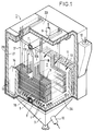
- Figure 1 is a perspective view of a bed according to the invention, its wall being partially torn off.
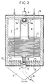
- Figure 2 is a cross-sectional view of this bed.
- Bedroom 2 is equipped with a lower box fluidizing air supply 3, nozzles 4 of fluidization air injection arranged on the wall lower 2A of the chamber 2 and of a heat exchanger 5 consisting of a plurality of parallel arrangements of tubes conveying a heat transfer fluid, for example steam, arranged transversely to chamber 2 and suspended from the upper wall 2B of chamber 2, each arrangement of tubes being connected at the bottom to an inlet manifold heat transfer fluid 6 consisting of a tube arranged longitudinally to the casing 1 and in the upper part to a outlet manifold of this heated fluid 7 consisting of a tube placed longitudinally in the box 1.
- a heat transfer fluid for example steam
- Such a bed is generally intended for an installation combustion system comprising a circulating fluidized bed hearth comprising a gas outlet opening into a cyclone of separation whose recovered solids are treated in this external fluidized bed before being at least partially reinjected into the circulating fluidized bed hearth.
- the inlet manifold 6 is housed in the wall lower 2A of chamber 2 and arranged in the plane central of bedroom 2. More specifically, it is housed in a slot 9 made in the bottom wall 2A of the chamber 2 and coated with sand or concrete 16, which ensures its fixation and its protection.
- a supply line in heat transfer fluid 10 passes through the fluidization box 3 and is connected to the inlet manifold 6 by a connector You.
- the arrangements of heat exchange tubes which are so classic essentially horizontal and hairpin hair and extend to the height of the walls 13, 14.
- the fixtures are hung in pairs on the wall upper 2B of chamber 2 by two supporting tubes vertical 17, 18 which are connected to the inlet manifold 6, pass through the upper wall 2B and return via return sections 17A, 18A connect to the manifold outlet 7 to which the tubes of the connection arrangements are connected tubes.
- these support tubes 17, 18 can be of the type described in patent document FR-2 622 963 and be joined to the horizontal sections by connecting parts providing both support mechanical and hydraulic connection, support tubes constituting an extension of one of the pin tubes to hair.
- the horizontal hairpin tubes are all the same length which eliminates any tension _differential in the support tubes 17, 18.
- the concrete collector outlet 7 is arranged inside bedroom 2, in the central plane longitudinal of chamber 2 and more precisely under the upper wall 2B of chamber 2 and is equipped with at least an outlet pipe for the heated heat transfer fluid 8 passing through this upper wall 2B and connected to the outlet manifold 7 by a tee fitting ensuring also the suspension of the outlet manifold 7 on the wall upper 2B.
- Such a bed allows a particularly manufacturing improved, which reduces manufacturing and assembly on site.
- the box 1 without its upper wall can be made in a first set, like an open box.
- the upper wall with collectors 7, 6 and the suspended tube arrangements 5 can be prefabricated in a second set, in the workshop or on site. It is enough during the final assembly, introduce the second from above set in the first set, the input manifold 6 being installed in the slot 9, placed on the metal sheet 20 then coated with sand or concrete.
- the complete disassembly of the device is carried out by destruction of any concrete 16 and removal from above of the second set.
- the sanding of the inlet manifold 6 facilitates disassembly of the latter and any intervention on this one.
- a partial disassembly is carried out by cutting off the pair damaged tube arrangements and the support tubes 17, 18 correspondents just above and just below the pair of tube arrangements and translating this pair of arrangements in the box up or down in order to carry out the repair on the tube arrangements cleared.
- disassembly requires less space than in known beds and it is thus possible to make a bed with less height and size.
Landscapes
- Engineering & Computer Science (AREA)
- Chemical & Material Sciences (AREA)
- Combustion & Propulsion (AREA)
- Physics & Mathematics (AREA)
- Thermal Sciences (AREA)
- Mechanical Engineering (AREA)
- General Engineering & Computer Science (AREA)
- Fluidized-Bed Combustion And Resonant Combustion (AREA)
- Heat-Exchange Devices With Radiators And Conduit Assemblies (AREA)
- Devices And Processes Conducted In The Presence Of Fluids And Solid Particles (AREA)
Claims (7)
- Dichtes Wirbelbett, das in einem Reaktorbehälter (1) eine Kammer (2) umfaßt, in der die Feststoffe eintreten und das mit einem unteren Versorgungsbehälter mit Wirbelluft (3) versehen ist, mit Injektionsdüsen für Wirbelluft (4), die an der unteren Wand (2A) angeordnet sind, und einem Wärmetauscher (5), der aus einer Mehrzahl von parallelen Röhrenanordnungen gebildet ist, die ein Wärmeträgerfluid führen, welche an der oberen Wand (2B) der Kammer (2) aufgehängt sind, wobei jede Röhrenanordnung mit einem Eingangskollektor für das Wärmeträgerfluid (6) verbunden ist, der aus einer Röhre gebildet wird, die längs am Reaktorbehälter (1) angeordnet ist, und im oberen Teil an der Innenseite der Kammer (2) mit einem Ausgangskollektor (7) für das erwärmte Fluid, gebildet aus einer Röhre, die längs am Reaktorbehälter (1) angeordnet ist, und mit zumindest einem Ausgangsstutzen (8) für das erwärmte Wärmeträgerfluid ausgestattet ist, der eine Wand der Kammer (2) durchdringt, dadurch gekennzeichnet, daß die parallelen Röhrenanordnungen transversal in der Kammer (2) angeordnet sind, wobei der Eingangskollektor (6) im unteren Teil in der unteren Wand (2A) der Kammer vorgesehen ist.
- Bett nach Anspruch 1, dadurch gekennzeichnet, daß der Ausgangskollektor (7) unter der oberen Wand (2B) der Kammer (2) angeordnet ist und daß der Stutzen (8) die obere Wand (2B) durchdringt.
- Bett nach einem der vorhergehenden Ansprüche, dadurch gekennzeichnet, daß die zwei Kollektoren (6, 7) in der zentralen Längsebene der Kammer (2) angeordnet sind.
- Bett nach Anspruch 3, dadurch gekennzeichnet, daß sämtliche Röhren einer jeden Röhrenanordnung im wesentlichen eine identische Länge haben.
- Bett nach einem der vorhergehenden Ansprüche, dadurch gekennzeichnet, daß der Eingangskollektor (6) in einem Fenster (9) angeordnet ist, das in der unteren Wand (2A) der Kammer (2) ausgebildet ist, und mit Sand ummantelt ist.
- Bett nach einem der vorhergehenden Ansprüche, dadurch gekennzeichnet, daß eine Kanalisierung zur Versorgung mit Wärmeträgerfluid (10) den Verwirbelungsbehälter (3) durchquert und mit dem Eingangskollektor (6) verbunden ist.
- Verbrennungsinstallation mit einer zirkulierenden Wirbelschichtbefeuerung, umfassend einen Ausgang für das Gas, der in einem Separationszyklon mündet, in dem die rückgewonnenen Feststoffe in einem externen Wirbelbett entsprechend einem der vorhergehenden Ansprüche bearbeitet werden.
Applications Claiming Priority (2)
| Application Number | Priority Date | Filing Date | Title |
|---|---|---|---|
| FR9601130A FR2744037B1 (fr) | 1996-01-31 | 1996-01-31 | Lit fluidise externe destine a equiper un foyer a lit fluidise circulant |
| FR9601130 | 1996-01-31 |
Publications (2)
| Publication Number | Publication Date |
|---|---|
| EP0787946A1 EP0787946A1 (de) | 1997-08-06 |
| EP0787946B1 true EP0787946B1 (de) | 2000-06-28 |
Family
ID=9488661
Family Applications (1)
| Application Number | Title | Priority Date | Filing Date |
|---|---|---|---|
| EP97400213A Expired - Lifetime EP0787946B1 (de) | 1996-01-31 | 1997-01-30 | Externe Wirbelschicht zur Ausrüstung einer zirkulierenden Wirbelschichtfeuerung |
Country Status (10)
| Country | Link |
|---|---|
| EP (1) | EP0787946B1 (de) |
| CN (1) | CN1078093C (de) |
| DE (1) | DE69702352T2 (de) |
| DK (1) | DK0787946T3 (de) |
| ES (1) | ES2148910T3 (de) |
| FR (1) | FR2744037B1 (de) |
| GR (1) | GR3034383T3 (de) |
| PT (1) | PT787946E (de) |
| RU (1) | RU2161283C2 (de) |
| ZA (1) | ZA97779B (de) |
Cited By (8)
| Publication number | Priority date | Publication date | Assignee | Title |
|---|---|---|---|---|
| US8961743B2 (en) | 2007-11-20 | 2015-02-24 | Ensyn Renewables, Inc. | Rapid thermal conversion of biomass |
| US9044727B2 (en) | 2011-09-22 | 2015-06-02 | Ensyn Renewables, Inc. | Apparatuses and methods for controlling heat for rapid thermal processing of carbonaceous material |
| US9102889B2 (en) | 2011-12-12 | 2015-08-11 | Ensyn Renewables, Inc. | Fluidized catalytic cracker riser quench system |
| US9127208B2 (en) | 2006-04-03 | 2015-09-08 | Pharmatherm Chemicals, Inc. | Thermal extraction method and product |
| US9347005B2 (en) | 2011-09-13 | 2016-05-24 | Ensyn Renewables, Inc. | Methods and apparatuses for rapid thermal processing of carbonaceous material |
| US9422478B2 (en) | 2010-07-15 | 2016-08-23 | Ensyn Renewables, Inc. | Char-handling processes in a pyrolysis system |
| US9441887B2 (en) | 2011-02-22 | 2016-09-13 | Ensyn Renewables, Inc. | Heat removal and recovery in biomass pyrolysis |
| US10041667B2 (en) | 2011-09-22 | 2018-08-07 | Ensyn Renewables, Inc. | Apparatuses for controlling heat for rapid thermal processing of carbonaceous material and methods for the same |
Families Citing this family (8)
| Publication number | Priority date | Publication date | Assignee | Title |
|---|---|---|---|---|
| FR2767380B1 (fr) * | 1997-08-18 | 1999-09-24 | Gec Alsthom Stein Ind | Dispositif d'echange thermique pour une chaudiere a lit fluidise circulant |
| US20110284359A1 (en) | 2010-05-20 | 2011-11-24 | Uop Llc | Processes for controlling afterburn in a reheater and for controlling loss of entrained solid particles in combustion product flue gas |
| US10400175B2 (en) | 2011-09-22 | 2019-09-03 | Ensyn Renewables, Inc. | Apparatuses and methods for controlling heat for rapid thermal processing of carbonaceous material |
| CN102425965B (zh) * | 2011-12-01 | 2013-08-14 | 兰州节能环保工程有限责任公司 | 粉粒状固体物料板式换热器 |
| US9670413B2 (en) | 2012-06-28 | 2017-06-06 | Ensyn Renewables, Inc. | Methods and apparatuses for thermally converting biomass |
| AR097135A1 (es) | 2013-06-26 | 2016-02-24 | Ensyn Renewables Inc | Sistemas y métodos para combustible renovable |
| DK3337966T3 (da) | 2015-08-21 | 2022-02-28 | Ensyn Renewables Inc | Opvarmningssystem med flydende biomasse |
| CA3048681A1 (en) | 2016-12-29 | 2018-07-05 | Ensyn Renewables, Inc. | Demetallization of liquid biomass |
Family Cites Families (7)
| Publication number | Priority date | Publication date | Assignee | Title |
|---|---|---|---|---|
| FR934373A (fr) * | 1945-03-29 | 1948-05-20 | Standard Oil Dev Co | Appareil de réaction |
| US3983927A (en) * | 1975-06-25 | 1976-10-05 | Dorr-Oliver Incorporated | Heat exchanger for fluidized bed reactor |
| US4607690A (en) * | 1985-11-29 | 1986-08-26 | Foster Wheeler Energy Corporation | Tube and support system for a heat exchanger |
| SE467984B (sv) * | 1990-05-08 | 1992-10-12 | Abb Carbon Ab | Pfbc-anlaeggning innefattande en braennkammare utformad som ett maanghoernigt prisma med sex sidovaeggar |
| FI97315C (fi) * | 1990-09-26 | 1996-11-25 | Stein Industrie | Leijukerroskattilan tulipesäseinämän jäähdytyslaitteisto |
| US5095854A (en) * | 1991-03-14 | 1992-03-17 | Foster Wheeler Development Corporation | Fluidized bed reactor and method for operating same utilizing an improved particle removal system |
| US5239946A (en) * | 1992-06-08 | 1993-08-31 | Foster Wheeler Energy Corporation | Fluidized bed reactor system and method having a heat exchanger |
-
1996
- 1996-01-31 FR FR9601130A patent/FR2744037B1/fr not_active Expired - Lifetime
-
1997
- 1997-01-30 EP EP97400213A patent/EP0787946B1/de not_active Expired - Lifetime
- 1997-01-30 DK DK97400213T patent/DK0787946T3/da active
- 1997-01-30 ZA ZA9700779A patent/ZA97779B/xx unknown
- 1997-01-30 DE DE69702352T patent/DE69702352T2/de not_active Expired - Fee Related
- 1997-01-30 ES ES97400213T patent/ES2148910T3/es not_active Expired - Lifetime
- 1997-01-30 PT PT97400213T patent/PT787946E/pt unknown
- 1997-01-30 RU RU97101343/06A patent/RU2161283C2/ru active
- 1997-01-31 CN CN97104868A patent/CN1078093C/zh not_active Expired - Lifetime
-
2000
- 2000-09-13 GR GR20000402072T patent/GR3034383T3/el not_active IP Right Cessation
Cited By (18)
| Publication number | Priority date | Publication date | Assignee | Title |
|---|---|---|---|---|
| US9127208B2 (en) | 2006-04-03 | 2015-09-08 | Pharmatherm Chemicals, Inc. | Thermal extraction method and product |
| US8961743B2 (en) | 2007-11-20 | 2015-02-24 | Ensyn Renewables, Inc. | Rapid thermal conversion of biomass |
| US9422478B2 (en) | 2010-07-15 | 2016-08-23 | Ensyn Renewables, Inc. | Char-handling processes in a pyrolysis system |
| US9441887B2 (en) | 2011-02-22 | 2016-09-13 | Ensyn Renewables, Inc. | Heat removal and recovery in biomass pyrolysis |
| US9347005B2 (en) | 2011-09-13 | 2016-05-24 | Ensyn Renewables, Inc. | Methods and apparatuses for rapid thermal processing of carbonaceous material |
| US9044727B2 (en) | 2011-09-22 | 2015-06-02 | Ensyn Renewables, Inc. | Apparatuses and methods for controlling heat for rapid thermal processing of carbonaceous material |
| US10041667B2 (en) | 2011-09-22 | 2018-08-07 | Ensyn Renewables, Inc. | Apparatuses for controlling heat for rapid thermal processing of carbonaceous material and methods for the same |
| US9102890B2 (en) | 2011-12-12 | 2015-08-11 | Ensyn Renewables, Inc. | Fluidized catalytic cracking apparatus |
| US9120988B2 (en) | 2011-12-12 | 2015-09-01 | Ensyn Renewables, Inc. | Methods to increase gasoline yield |
| US9127224B2 (en) | 2011-12-12 | 2015-09-08 | Ensyn Renewables, Inc. | External steam reduction method in a fluidized catalytic cracker |
| US9120989B2 (en) | 2011-12-12 | 2015-09-01 | Ensyn Renewables, Inc. | Generating cellulosic-renewable identification numbers in a refinery |
| US9127223B2 (en) | 2011-12-12 | 2015-09-08 | Ensyn Renewables, Inc. | Systems and methods for renewable fuel |
| US9120990B2 (en) | 2011-12-12 | 2015-09-01 | Ensyn Renewables, Inc. | Systems for fuels from biomass |
| US9410091B2 (en) | 2011-12-12 | 2016-08-09 | Ensyn Renewables, Inc. | Preparing a fuel from liquid biomass |
| US9109177B2 (en) | 2011-12-12 | 2015-08-18 | Ensyn Renewables, Inc. | Systems and methods for renewable fuel |
| US9422485B2 (en) | 2011-12-12 | 2016-08-23 | Ensyn Renewables, Inc. | Method of trading cellulosic-renewable identification numbers |
| US9102888B2 (en) | 2011-12-12 | 2015-08-11 | Ensyn Renewables, Inc. | Methods for renewable fuels with reduced waste streams |
| US9102889B2 (en) | 2011-12-12 | 2015-08-11 | Ensyn Renewables, Inc. | Fluidized catalytic cracker riser quench system |
Also Published As
| Publication number | Publication date |
|---|---|
| RU2161283C2 (ru) | 2000-12-27 |
| DK0787946T3 (da) | 2000-10-16 |
| CN1078093C (zh) | 2002-01-23 |
| GR3034383T3 (en) | 2000-12-29 |
| PT787946E (pt) | 2000-12-29 |
| EP0787946A1 (de) | 1997-08-06 |
| ZA97779B (en) | 1997-08-13 |
| CN1167651A (zh) | 1997-12-17 |
| ES2148910T3 (es) | 2000-10-16 |
| DE69702352D1 (de) | 2000-08-03 |
| DE69702352T2 (de) | 2001-02-15 |
| FR2744037A1 (fr) | 1997-08-01 |
| FR2744037B1 (fr) | 1998-02-27 |
Similar Documents
| Publication | Publication Date | Title |
|---|---|---|
| EP0787946B1 (de) | Externe Wirbelschicht zur Ausrüstung einer zirkulierenden Wirbelschichtfeuerung | |
| FR2486223A1 (fr) | Echangeur de chaleur a lit fluidise | |
| FR2564747A1 (fr) | Procede et moyens pour controler le fonctionnement d'un reacteur a lit fluidise recycle | |
| FR2526129A1 (fr) | Chaudiere a lit fluidise | |
| EP1772670B1 (de) | Zirkulierende Wirbelschichtfeuerungsanlage mit umwandelbarem Verbrennungsverfahren | |
| FR2541435A1 (fr) | Generateur thermique pour la realisation du chauffage de fluide par echange thermique au moyen d'un lit fluidise et le procede pour sa mise en oeuvre | |
| KR20100057657A (ko) | 원심 분리기 조립체 | |
| EP0236647B1 (de) | Wirbelbettwärmeerzeuger mit Mitteln für Aschenbeseitigung und Wärmerückgewinnung | |
| EP0320403B1 (de) | Gekühlter Fliessbettrost | |
| EP0864834B1 (de) | Wärmetauscher mit dichter Wirbelschicht kombiniert mit einem Reaktor mit zirkulierender Wirbelschicht | |
| EP2012073B1 (de) | Wärmetauscher für einen Kessel, Kessel mit so einem Wärmetauscher und Verfahren zur Anfertigung so eines Wärmetauschers | |
| EP0694749B1 (de) | Feststoffpartikel-Kühlungseinrichtung am Ausgang einer Verarbeitungsanordnung | |
| FR2752926A1 (fr) | Echangeur de chaleur d'encombrement reduit | |
| FR2547899A1 (fr) | Chaudiere compacte a lit fluidise | |
| EP0044316A1 (de) | Wirbelschicht-verbrennungsvorrichtung | |
| EP0180497B1 (de) | Wirbelschischtapparat mit Wärmetauscher und mit einem Einblasnetz für Sekundärluft | |
| FR2485173A1 (fr) | Generateur de chaleur equipe de bruleurs a gaz formant chaudiere a condensation | |
| BE879140R (fr) | Separateur-surchauffeur de vapeur vertical | |
| FR2547648A1 (fr) | Chaudiere a condensation | |
| FR2602313A1 (fr) | Appareil recuperateur de chaleur pour installations de chauffage | |
| FR2535026A1 (fr) | Chaudiere a bois ou autres materiaux combustibles solides | |
| BE465328A (de) | ||
| BE434989A (de) | ||
| BE399601A (de) | ||
| FR2583858A1 (fr) | Chaudiere a combustible solide a haut rendement |
Legal Events
| Date | Code | Title | Description |
|---|---|---|---|
| PUAI | Public reference made under article 153(3) epc to a published international application that has entered the european phase |
Free format text: ORIGINAL CODE: 0009012 |
|
| AK | Designated contracting states |
Kind code of ref document: A1 Designated state(s): BE DE DK ES GB GR IT PT SE |
|
| 17P | Request for examination filed |
Effective date: 19971206 |
|
| 17Q | First examination report despatched |
Effective date: 19990504 |
|
| RAP1 | Party data changed (applicant data changed or rights of an application transferred) |
Owner name: ALSTOM ENERGY SYSTEMS S.A. |
|
| GRAG | Despatch of communication of intention to grant |
Free format text: ORIGINAL CODE: EPIDOS AGRA |
|
| GRAG | Despatch of communication of intention to grant |
Free format text: ORIGINAL CODE: EPIDOS AGRA |
|
| GRAG | Despatch of communication of intention to grant |
Free format text: ORIGINAL CODE: EPIDOS AGRA |
|
| GRAH | Despatch of communication of intention to grant a patent |
Free format text: ORIGINAL CODE: EPIDOS IGRA |
|
| GRAH | Despatch of communication of intention to grant a patent |
Free format text: ORIGINAL CODE: EPIDOS IGRA |
|
| GRAA | (expected) grant |
Free format text: ORIGINAL CODE: 0009210 |
|
| AK | Designated contracting states |
Kind code of ref document: B1 Designated state(s): BE DE DK ES GB GR IT PT SE |
|
| REF | Corresponds to: |
Ref document number: 69702352 Country of ref document: DE Date of ref document: 20000803 |
|
| GBT | Gb: translation of ep patent filed (gb section 77(6)(a)/1977) |
Effective date: 20000724 |
|
| ITF | It: translation for a ep patent filed | ||
| REG | Reference to a national code |
Ref country code: DK Ref legal event code: T3 Ref country code: ES Ref legal event code: FG2A Ref document number: 2148910 Country of ref document: ES Kind code of ref document: T3 |
|
| REG | Reference to a national code |
Ref country code: PT Ref legal event code: SC4A Free format text: AVAILABILITY OF NATIONAL TRANSLATION Effective date: 20000911 |
|
| PLBE | No opposition filed within time limit |
Free format text: ORIGINAL CODE: 0009261 |
|
| STAA | Information on the status of an ep patent application or granted ep patent |
Free format text: STATUS: NO OPPOSITION FILED WITHIN TIME LIMIT |
|
| 26N | No opposition filed | ||
| PGFP | Annual fee paid to national office [announced via postgrant information from national office to epo] |
Ref country code: PT Payment date: 20011221 Year of fee payment: 6 |
|
| PGFP | Annual fee paid to national office [announced via postgrant information from national office to epo] |
Ref country code: GR Payment date: 20011228 Year of fee payment: 6 |
|
| REG | Reference to a national code |
Ref country code: GB Ref legal event code: IF02 |
|
| PGFP | Annual fee paid to national office [announced via postgrant information from national office to epo] |
Ref country code: DK Payment date: 20020102 Year of fee payment: 6 Ref country code: SE Payment date: 20020102 Year of fee payment: 6 |
|
| PGFP | Annual fee paid to national office [announced via postgrant information from national office to epo] |
Ref country code: BE Payment date: 20020220 Year of fee payment: 6 |
|
| PGFP | Annual fee paid to national office [announced via postgrant information from national office to epo] |
Ref country code: GB Payment date: 20021227 Year of fee payment: 7 |
|
| PG25 | Lapsed in a contracting state [announced via postgrant information from national office to epo] |
Ref country code: SE Free format text: LAPSE BECAUSE OF NON-PAYMENT OF DUE FEES Effective date: 20030131 Ref country code: DK Free format text: LAPSE BECAUSE OF NON-PAYMENT OF DUE FEES Effective date: 20030131 Ref country code: BE Free format text: LAPSE BECAUSE OF NON-PAYMENT OF DUE FEES Effective date: 20030131 |
|
| PG25 | Lapsed in a contracting state [announced via postgrant information from national office to epo] |
Ref country code: PT Free format text: LAPSE BECAUSE OF NON-PAYMENT OF DUE FEES Effective date: 20030731 |
|
| PG25 | Lapsed in a contracting state [announced via postgrant information from national office to epo] |
Ref country code: GR Free format text: LAPSE BECAUSE OF NON-PAYMENT OF DUE FEES Effective date: 20030804 |
|
| REG | Reference to a national code |
Ref country code: DK Ref legal event code: EBP |
|
| EUG | Se: european patent has lapsed | ||
| PGFP | Annual fee paid to national office [announced via postgrant information from national office to epo] |
Ref country code: DE Payment date: 20040108 Year of fee payment: 8 |
|
| PGFP | Annual fee paid to national office [announced via postgrant information from national office to epo] |
Ref country code: ES Payment date: 20040122 Year of fee payment: 8 |
|
| PG25 | Lapsed in a contracting state [announced via postgrant information from national office to epo] |
Ref country code: GB Free format text: LAPSE BECAUSE OF NON-PAYMENT OF DUE FEES Effective date: 20040130 |
|
| GBPC | Gb: european patent ceased through non-payment of renewal fee |
Effective date: 20040130 |
|
| PG25 | Lapsed in a contracting state [announced via postgrant information from national office to epo] |
Ref country code: IT Free format text: LAPSE BECAUSE OF NON-PAYMENT OF DUE FEES;WARNING: LAPSES OF ITALIAN PATENTS WITH EFFECTIVE DATE BEFORE 2007 MAY HAVE OCCURRED AT ANY TIME BEFORE 2007. THE CORRECT EFFECTIVE DATE MAY BE DIFFERENT FROM THE ONE RECORDED. Effective date: 20050130 |
|
| PG25 | Lapsed in a contracting state [announced via postgrant information from national office to epo] |
Ref country code: ES Free format text: LAPSE BECAUSE OF NON-PAYMENT OF DUE FEES Effective date: 20050131 |
|
| PG25 | Lapsed in a contracting state [announced via postgrant information from national office to epo] |
Ref country code: DE Free format text: LAPSE BECAUSE OF NON-PAYMENT OF DUE FEES Effective date: 20050802 |
|
| REG | Reference to a national code |
Ref country code: ES Ref legal event code: FD2A Effective date: 20050131 |