EP0790154A1 - Side impact air bag module - Google Patents
Side impact air bag module Download PDFInfo
- Publication number
- EP0790154A1 EP0790154A1 EP97102530A EP97102530A EP0790154A1 EP 0790154 A1 EP0790154 A1 EP 0790154A1 EP 97102530 A EP97102530 A EP 97102530A EP 97102530 A EP97102530 A EP 97102530A EP 0790154 A1 EP0790154 A1 EP 0790154A1
- Authority
- EP
- European Patent Office
- Prior art keywords
- inflator
- diffuser
- end portion
- wall portion
- vehicle
- Prior art date
- Legal status (The legal status is an assumption and is not a legal conclusion. Google has not performed a legal analysis and makes no representation as to the accuracy of the status listed.)
- Granted
Links
- 239000012530 fluid Substances 0.000 claims description 72
- 230000000903 blocking effect Effects 0.000 claims description 34
- 239000000463 material Substances 0.000 claims description 31
- 239000002184 metal Substances 0.000 claims description 14
- 238000005452 bending Methods 0.000 claims description 8
- 238000010438 heat treatment Methods 0.000 claims description 7
- 239000004744 fabric Substances 0.000 description 3
- 239000010985 leather Substances 0.000 description 2
- 230000004048 modification Effects 0.000 description 2
- 238000012986 modification Methods 0.000 description 2
- 239000004677 Nylon Substances 0.000 description 1
- 238000002485 combustion reaction Methods 0.000 description 1
- 238000010276 construction Methods 0.000 description 1
- 239000006260 foam Substances 0.000 description 1
- 230000013011 mating Effects 0.000 description 1
- 229920001778 nylon Polymers 0.000 description 1
- 239000004033 plastic Substances 0.000 description 1
- 239000002985 plastic film Substances 0.000 description 1
- 229920006255 plastic film Polymers 0.000 description 1
Images


Classifications
-
- B—PERFORMING OPERATIONS; TRANSPORTING
- B60—VEHICLES IN GENERAL
- B60R—VEHICLES, VEHICLE FITTINGS, OR VEHICLE PARTS, NOT OTHERWISE PROVIDED FOR
- B60R21/00—Arrangements or fittings on vehicles for protecting or preventing injuries to occupants or pedestrians in case of accidents or other traffic risks
- B60R21/02—Occupant safety arrangements or fittings, e.g. crash pads
- B60R21/16—Inflatable occupant restraints or confinements designed to inflate upon impact or impending impact, e.g. air bags
- B60R21/20—Arrangements for storing inflatable members in their non-use or deflated condition; Arrangement or mounting of air bag modules or components
- B60R21/207—Arrangements for storing inflatable members in their non-use or deflated condition; Arrangement or mounting of air bag modules or components in vehicle seats
-
- B—PERFORMING OPERATIONS; TRANSPORTING
- B60—VEHICLES IN GENERAL
- B60R—VEHICLES, VEHICLE FITTINGS, OR VEHICLE PARTS, NOT OTHERWISE PROVIDED FOR
- B60R21/00—Arrangements or fittings on vehicles for protecting or preventing injuries to occupants or pedestrians in case of accidents or other traffic risks
- B60R21/02—Occupant safety arrangements or fittings, e.g. crash pads
- B60R21/16—Inflatable occupant restraints or confinements designed to inflate upon impact or impending impact, e.g. air bags
- B60R21/26—Inflatable occupant restraints or confinements designed to inflate upon impact or impending impact, e.g. air bags characterised by the inflation fluid source or means to control inflation fluid flow
- B60R21/261—Inflatable occupant restraints or confinements designed to inflate upon impact or impending impact, e.g. air bags characterised by the inflation fluid source or means to control inflation fluid flow with means other than bag structure to diffuse or guide inflation fluid
-
- B—PERFORMING OPERATIONS; TRANSPORTING
- B60—VEHICLES IN GENERAL
- B60R—VEHICLES, VEHICLE FITTINGS, OR VEHICLE PARTS, NOT OTHERWISE PROVIDED FOR
- B60R21/00—Arrangements or fittings on vehicles for protecting or preventing injuries to occupants or pedestrians in case of accidents or other traffic risks
- B60R2021/0002—Type of accident
- B60R2021/0006—Lateral collision
-
- B—PERFORMING OPERATIONS; TRANSPORTING
- B60—VEHICLES IN GENERAL
- B60R—VEHICLES, VEHICLE FITTINGS, OR VEHICLE PARTS, NOT OTHERWISE PROVIDED FOR
- B60R21/00—Arrangements or fittings on vehicles for protecting or preventing injuries to occupants or pedestrians in case of accidents or other traffic risks
- B60R21/02—Occupant safety arrangements or fittings, e.g. crash pads
- B60R21/16—Inflatable occupant restraints or confinements designed to inflate upon impact or impending impact, e.g. air bags
- B60R21/20—Arrangements for storing inflatable members in their non-use or deflated condition; Arrangement or mounting of air bag modules or components
- B60R21/217—Inflation fluid source retainers, e.g. reaction canisters; Connection of bags, covers, diffusers or inflation fluid sources therewith or together
- B60R21/2176—Inflation fluid source retainers, e.g. reaction canisters; Connection of bags, covers, diffusers or inflation fluid sources therewith or together the air bag components being completely enclosed in a soft or semi-rigid housing or cover
Definitions
- the present invention relates to a vehicle safety apparatus and particularly relates to an air bag module including an inflatable vehicle occupant protection device, such as an air bag, for helping to protect a vehicle occupant in the event of a side impact to the vehicle.
- an air bag module including an inflatable vehicle occupant protection device, such as an air bag, for helping to protect a vehicle occupant in the event of a side impact to the vehicle.
- an air bag to help protect a vehicle occupant in the event of a side impact to a vehicle of a magnitude above a predetermined threshold.
- the air bag is stored in a deflated condition, together with an inflator, in a vehicle seat, for example.
- the inflator is actuated, and the air bag is inflated into a position between the vehicle occupant in the vehicle seat and the adjacent side structure of the vehicle such as a door or window of the vehicle or a body panel of the vehicle.
- the air bag helps protect the vehicle occupant from forcefully being struck by parts of the side structure of the vehicle.
- the air bag can also help protect the vehicle occupant from objects which might intrude into the vehicle, such as a pole or a tree, during the side impact.
- the present invention is a vehicle safety apparatus for helping to protect an occupant of a vehicle in the event of an impact to the vehicle.
- the apparatus comprises an inflatable occupant protection device which has a deflated condition and which is inflatable into a position adjacent to the vehicle occupant for helping to protect the vehicle occupant.
- the apparatus also includes an inflator which is actuatable to provide inflation fluid for inflating the inflatable device.
- the inflator has an axis, a first end portion, a second end portion, and a central portion between the first and second end portions.
- the apparatus further includes a diffuser receiving the inflator.
- the diffuser has a central wall portion and first and second opposite end portions.
- the apparatus includes means for supporting the diffuser and the inflator on the vehicle.
- the central wall portion of the diffuser is spaced radially outward from the central portion of the inflator to define a diffuser chamber between the central wall portion of the diffuser and the central portion of the inflator.
- the first end portion of the diffuser extends radially inward from the central wall portion of the diffuser and blocks axial movement of the inflator in a first axial direction.
- the second end portion of the diffuser has a radial portion extending radially inward from the central wall portion of the diffuser in a direction toward the axis. The radial portion of the diffuser blocks radial movement of the second end portion of the inflator and blocks axial movement of the inflator in a second axial direction opposite to the first axial direction.
- the present invention relates to a vehicle safety apparatus, and particularly relates to an air bag module including an inflatable vehicle occupant protection device, such as an air bag, for helping to protect a vehicle occupant in the event of a side impact to the vehicle of a magnitude sufficient to require inflation of the inflatable device.
- the present invention is applicable to various vehicle safety apparatus constructions. As representative of the present invention, Figs. 1-3 illustrate a vehicle safety apparatus or air bag module 10.
- the air bag module 10 (Fig. 1) is connected with a seat frame member 12 of a seat 14 for an occupant of a vehicle.
- the seat 14 includes a seat bottom cushion 16 and a seatback 18 connected with the seat bottom cushion.
- a forward direction in the vehicle is indicated by the arrow 20 (Fig. 1) and a rearward direction in the vehicle is indicated by the arrow 22.
- the air bag module 10 includes an inflatable device, illustrated schematically at 30, which is commonly known as an air bag.
- the air bag 30 is preferably made from a fabric material such as woven nylon.
- the air bag 30 can alternatively be made from a non-woven material, such as plastic film.
- the air bag module 10 also includes a cover indicated schematically at 32 (Fig. 2) which encloses the folded air bag 30.
- the cover 32 is opened by the inflating air bag 30 to enable deployment of the air bag into a position to help protect an occupant of the vehicle seat.
- the air bag module 10, including the cover 32 is located within the vehicle seatback 18 underneath the fabric material or leather covering of the seat.
- the air bag module 10 also includes an inflator 40.
- the inflator 40 is illustrated as an "augment" type inflator which includes both inflation fluid stored in a container and an ignitable material for heating and thereby increasing the pressure of the inflation fluid.
- the module 10 alternatively could include an inflator which contains only a stored quantity of pressurized inflation fluid, or a pyrotechnic inflator which uses the combustion of gas-generating material to generate inflation fluid in the form of gas to inflate the air bag 30.
- the inflator 40 includes a container 42 which defines an inflation fluid chamber 44.
- the inflation fluid chamber 44 contains a stored quantity of pressurized inflation fluid 46.
- At one end of the inflation fluid chamber 44 is a rupturable portion of the container or a rupturable member such as a burst disk 48.
- An ignitable material 50 is disposed within the container 42 at a location adjacent to the inflation fluid chamber 44 for, when ignited, heating inflation fluid 46 flowing from the inflation fluid chamber.
- An electrically actuatable igniter 52 for igniting the ignitable material 50 and for opening the inflation fluid chamber 44, is disposed adjacent to the ignitable material.
- a pair of lead wires 76 extend from a cylindrical end portion 74 of the igniter 52.
- the inflator 40 has a generally cylindrical configuration centered on a longitudinal axis 60.
- a central portion 62 of the inflator 40 includes a cylindrical side wall 64 of the inflator.
- the side wall 64 has a cylindrical outer side surface 66.
- the central portion 62 of the inflator 40 also includes a plurality of fluid outlets 68 which are spaced apart 180° around the circumference of the inflator.
- a first end portion 70 of the inflator 40 has a flat, radially extending end surface 72.
- the end portion 74 of the igniter 52 projects from the end surface 72 of the inflator 40.
- a second end portion 80 of the inflator 40 has a domed configuration including a convex outer surface 82.
- the convex outer surface 82 of the second end portion 80 of the inflator 40 merges with the cylindrical outer surface 66 of the central portion 62 of the inflator.
- the second end portion 80 of the inflator 40 includes one axial end portion (to the left as viewed in Fig. 3) of the inflation fluid chamber 44.
- the vehicle in which the air bag module 10 is mounted includes known means indicated schematically at 90 (Fig. 1) for sensing a side impact to the vehicle and for actuating the inflator 40 in response to the sensing of a side impact.
- the means 90 may include a side impact sensor and vehicle circuitry for electrically actuating the inflator 40 in response to sensing a side impact to the vehicle above a predetermined threshold.
- the means 90 is electrically connected with the igniter 52 of the inflator 40, via the lead wires 76, for providing an actuation signal to the inflator.
- the air bag module 10 also includes a diffuser 100 (Figs. 2 and 3) which may also be referred to herein as a retainer assembly or retainer.
- the diffuser 100 is made from a single piece of metal and has an elongate, generally cylindrical configuration.
- the diffuser 100 includes a central portion 102, a first end portion 110, and a second end portion 120.
- a cylindrical side wall 122 of the diffuser 100 extends for the length of the central portion 102 of the diffuser.
- the side wall 122 is centered on the axis 60 and has opposite inner and outer side surfaces 124 and 126.
- the central portion 102 of the diffuser 100, including the side wall 122, is spaced radially outward from the cylindrical outer surface 66 of the inflator 40.
- An annular, axially extending, diffuser chamber 128 is defined between the side wall 122 of the diffuser 100 and the cylindrical outer surface 66 of the inflator 40.
- a series of circular fluid outlet openings 129 are formed in the side wall 122 of the diffuser 100 and communicate between the diffuser chamber 128 and the exterior of the diffuser. As illustrated, the openings 129 are aligned in a row centered on a line which extends parallel to the longitudinal axis 60.
- a pair of mounting bolts 130 extend radially outward from the side wall 122 of the diffuser 100, opposite the fluid outlet openings 129.
- the first end portion 110 of the diffuser 100 is a clamping portion of the diffuser which is disposed at and supports the first end portion 70 of the inflator 40.
- the first end portion 110 of the diffuser 100 includes a frustoconical wall portion 132 which extends axially away from and radially inward from the cylindrical side wall 122 of the diffuser. The frustoconical wall portion 132 engages and supports the first end portion 70 of the inflator 40.
- the first end portion 110 of the diffuser 100 also includes a flat, annular wall portion 134 which extends radially inward from the frustoconical wall portion 132.
- the wall portion 134 overlies the radially extending outer end surface 72 of the inflator 40.
- the wall portion 134 has a circular opening 136 which receives the cylindrical outer end portion 74 of the igniter 52.
- the opening 136 is preferably larger in diameter than the outer end portion 74 of the igniter 52. Alternatively, the opening 136 may engage and support the outer end portion 74 of the igniter 52.
- the first end portion 70 of the inflator is thus supported on the first end portion 110 of the diffuser 100.
- the first end portion 110 of the diffuser 100 blocks radial movement of the first end portion of the inflator relative to the diffuser.
- the first end portion 110 of the diffuser 100 also blocks axial movement of the inflator 40, relative to the diffuser, in a first axial direction as indicated by the arrow 138, that is to the right as viewed in Fig. 3.
- the first end portion 110 of the diffuser 100 closes and seals the diffuser chamber 128 at one end, that is, to the right as viewed in Fig. 3.
- a second end portion 120 of the diffuser 100 is a clamping portion of the diffuser which is disposed at and supports the second end portion 80 of the inflator 40.
- the second end portion 120 of the diffuser 100 comprises a curled wall portion or curl portion 140 of the diffuser.
- the second end portion 120 is formed as an extension of the cylindrical wall portion 122 of the diffuser 100.
- the second end portion 120 of the diffuser has a cylindrical configuration as shown in phantom in Fig. 3 prior to assembly of the air bag module 100.
- the second end portion 120 of the diffuser 100 is movable from the cylindrical condition shown in phantom in Fig. 3 to the curled condition shown in solid lines in Fig. 3 during assembly of the air bag module 10.
- the curl portion 140 has an arcuate cross-sectional configuration centered on a circular bending axis 141, as seen in Fig. 3.
- the curl portion 140 of the diffuser 100 extends radially inward from the cylindrical side wall 122 at a plurality of locations which are disposed in a circular array which is centered on the axis 60.
- the curl portion 140 of the diffuser 100 extends radially inward from the cylindrical side wall 122, in a uniform manner, for 360° around the axis 60.
- the curl portion 140 defines a circular opening 142 which receives the second end portion 80 of the inflator 40.
- An inner side surface 146 of the curl portion 140 extends as a continuation of the inner side surface 124 of the cylindrical side wall 122 of the diffuser 100.
- An outer side surface 150 of the curl portion 140 extends as a continuation of the outer side surface 126 of the cylindrical side wall 122 of the diffuser 100.
- the outer side surface 150 of the curl portion 140 engages the convex outer surface 82 of the domed second end portion 80 of the inflator 40. This engagement occurs along a circular area or line of engagement 154 extending around and centered on the axis 60, in a uniform manner for 360° around the axis. That is, the curl portion 140 of the diffuser 100 engages and supports the inflator 40 at a plurality or series of locations which are disposed in a circular array extending around the axis 60.
- the second end portion 120 of the diffuser 100 closes and seals the diffuser chamber 128 at one end, that is, to the left as viewed in Fig. 3.
- the second end portion 120 of the diffuser 100 blocks axial movement of the inflator 40, relative to the diffuser, in a second axial direction as indicated by the arrow 158, that is, to the left as viewed in Fig. 3.
- the second end portion 120 of the diffuser 100 also blocks radial movement of the second end portion 80 of the inflator 40, relative to the diffuser.
- the inflator 40 is inserted into the diffuser 100 when the diffuser has a completely cylindrical configuration, that is, when the end portions 110 and 120 of the diffuser are not yet bent radially inward from the cylindrical side wall 122.
- the first end portion 110 of the diffuser 100 is then deformed inward into engagement with the first end portion 70 of the inflator 40.
- the second end portion 120 of the diffuser 100 is then curled into engagement with the second end portion 80 of the inflator 40.
- the inflator 40 is clamped in the diffuser 100 with an axially directed force in the range of from about 80 pounds to about 300 pounds.
- the inflator 40 engages, or is connected with, the diffuser 100 only at the end portions 110 and 120 of the diffuser; there is no other connection or engagement between the inflator and the diffuser.
- the assembly of the inflator 40 and the diffuser 100 is then inserted into the air bag 30 and the cover 32.
- the mounting bolts 130 extend through fastener openings in the air bag 30 and the cover 32.
- the lead wires 76 extend out of the air bag 30 through another opening (not shown) in the air bag.
- a pair of nuts 160 secure a mounting bracket 162 on the mounting bolts 130.
- the mounting bracket 162 is then secured by fasteners 164 to the seat frame member 12 in the seatback 18.
- the module 10 is preferably mounted on the seatback 18 so that when the seatback is reclined at an angle of 25° from the vertical and the inflator 40 is actuated, the air bag 30 deploys in a generally forward and upward direction as illustrated in Fig. 1.
- the igniter 52 is actuated.
- the ignitable material 50 ignites and the burst disk 48 ruptures.
- the inflation fluid 46 flows out of the container 42, past the ignitable material 50.
- the inflation fluid is heated and its pressure increases.
- the inflation fluid 46 flows out of the inflator 40, through the fluid outlets 68 in the inflator, and into the diffuser chamber 128.
- the inflation fluid 46 flows out of the diffuser chamber 128, through the openings 129 in the diffuser 100, and into the air bag 30.
- the rapidly flowing inflation fluid causes the air bag 30 to cut through the portions of the seatback 18 which overlie the module 10, such as foam cushion material and/or fabric material or leather covering of the seat.
- the air bag 30 inflates from a folded, stored condition to an inflated condition as illustrated in Fig. 1.
- Fig. 4 illustrates a portion of an air bag module 10a which is constructed in accordance with a second embodiment of the present invention. Parts of the air bag module 10a which are the same as or similar to corresponding parts of the module 10 are given the same reference numeral with the suffix "a" added for clarity.
- the air bag module 10a includes an inflator 40a which is the same as the inflator 40 (Figs. 1-3).
- the module 10a includes a retainer or diffuser 100a, which may also be referred to herein as a retainer, which is generally similar to the diffuser 100 (Figs. 1-3).
- the curl portion 140a does not engage the domed second end portion 80a of the inflator 40a.
- a cushion 170 is disposed between the curl portion 140a of the diffuser 100a and the second end portion 80a of the inflator 40a. The cushion 170 and the diffuser 100a together form a retainer assembly of the air bag module 10a.
- the cushion 170 is made from a compressible material such as rubber or plastic and includes a generally hemispherical main body portion 172.
- the main body portion 172 of the cushion 170 is closely fitted around the domed end portion 80a of the inflator 40a.
- the main body portion 172 of the cushion 170 has a generally hemispherical outer side surface 174.
- a plurality of ribs 176 project radially outward from the outer side surface 174 of the main body portion 172 of the cushion 170.
- the ribs 176 engage the inner side surface 124a of the cylindrical wall portion 122a of the diffuser 100a.
- the engagement of the ribs 176 with the diffuser 100a maintains the second end portion 80a of the inflator 40a at a position centered on the axis 60a.
- the curl portion 140a of the diffuser 100a engages the outer side surface 174 of the main body portion 172 of the cushion 170.
- An annular edge 180 of the curl portion 140a extends into the material of the main body portion 172 of the cushion 170 and clamps the cushion against the second end portion 80a of the inflator 40a.
- the cushion 170 blocks metal to metal contact between the second end portion 120a of the diffuser 100a and the second end portion 80a of the inflator 40a.
- Fig. 5 illustrates a portion of an air bag module 10b which is constructed in accordance with a third embodiment of the present invention.
- Parts of the air bag module 10b which are the same as or similar to corresponding parts of the modules 10 (Figs. 1-3) or 10a (Fig. 4) are given the same reference numeral with the suffix "b" added for clarity.
- the air bag module 10b includes an inflator 40b which is the same as the inflator 40 (Figs. 1-3).
- the module 10b includes a retainer or diffuser 100b which is generally similar to the diffuser 100 (Figs. 1-3).
- a second end portion 120b of the diffuser 100b is disposed at and supports the second end portion 80b of the inflator 40b.
- the second end portion 120b of the diffuser 100b comprises a radial formed wall portion or radial portion 140b of the diffuser.
- the second end portion 120b is formed as an extension of the cylindrical wall portion 122b of the diffuser 100b.
- the second end portion 120b of the diffuser has a cylindrical configuration, shown in phantom in Fig. 5, prior to assembly of the air bag module 100b.
- the second end portion 120b of the diffuser 100b is movable from the cylindrical condition to the condition shown in solid lines in Fig. 5 during assembly of the air bag module 10b.
- the radial portion 140b of the diffuser 100b is similar to the curl portion 140 of the diffuser 100 (Figs. 1-3) with the exception that the radial portion does not curl axially toward the first end portion 110b of the diffuser.
- the radial portion 140b of the diffuser 100b extends radially inward from the cylindrical side wall 122b at least at a plurality of locations which are disposed in a circular array which is centered on the axis 60b.
- the radial portion 140b of the diffuser 100b has an arcuate or hemispherical wall portion 190b which extends radially inward from the cylindrical side wall 122b, in a uniform manner, for 360° around the axis 60b.
- the radial portion 140b could, alternatively, be a series of discrete sections in a circular array.
- the arcuate wall portion 190b of the radial portion 140b of the diffuser 100b terminates in an annular, radially extending inner wall portion 192b.
- a cushion 170b is disposed between the radial portion 140b of the diffuser 100b and the second end portion 80b of the inflator 40b.
- the cushion 170b and the diffuser 100b together form a retainer assembly of the air bag module 10b.
- the cushion 170b includes a generally hemispherical main body portion 172b which is closely fitted around the domed end portion 80b of the inflator 40b.
- the main body portion 172b of the cushion 170b has a generally hemispherical outer side surface 174b when in an undeformed condition (not shown).
- the radial portion 140b of the diffuser 100b engages the outer side surface 174b of the main body portion 172b of the cushion 170b.
- An annular edge 194b of the radial portion 140b compresses the material of the main body portion 172b of the cushion 170b and clamps the cushion against the second end portion 80b of the inflator 40b.
- the cushion 170b blocks metal to metal contact between the second end portion 120b of the diffuser 100b and the second end portion 80b of the inflator 40b.
- Figs. 6 and 7 illustrate portions of an air bag module 10c which is constructed in accordance with a fourth embodiment of the present invention.
- the air bag module 10c may be substituted for the air bag module 10, in the vehicle seat 14 (Fig. 1).
- the air bag module 10c (Figs. 6 and 7) includes an elongate inflator 40c.
- the inflator 40c includes a cylindrical body portion 200 having a cylindrical outer surface 202 centered on an axis 60c of the inflator.
- a cylindrical neck portion 204 of the inflator 40c projects from the body portion 200 at a first end portion 206 of the inflator.
- the neck portion 204 is smaller in diameter than the body portion 200.
- the neck portion 204 includes a plurality of inflation fluid outlets 208.
- An electrical connector 210 is located at a second end portion 212 of the inflator 40c.
- the module 10b includes a tubular retainer assembly 220 for securing the inflator 40c in position relative to the seat member 12 of the vehicle seat 14.
- the retainer assembly 220 includes a tubular diffuser or retainer 100c formed from one piece of sheet metal stamped and formed to the generally cylindrical configuration shown in Fig. 6.
- a pair of externally threaded weld studs 130c are secured to the retainer 100c along an imaginary baseline 222 of the retainer.
- the retainer 100c includes first and second side walls 230 and 240 on opposite sides of the baseline 222.
- the first side wall 230 has a cylindrical portion 232 which extends about 90° around the circumference of the retainer 100b in a direction away from the baseline 222.
- the cylindrical portion 232 of the first side wall 230 has a cylindrical inner surface 234.
- the second side wall 240 has a cylindrical portion 242 which extends about 90° around the circumference of the retainer 100b in a direction away from the baseline 222.
- the cylindrical portion 242 of the second side wall 240 has a cylindrical inner surface 244 which is presented toward the cylindrical inner surface 234 of the first side wall 230.
- the side wall inner surfaces 234 and 244 have the same radius of curvature as the cylindrical outer side surface 202 of the body portion 200 of the inflator 40c.
- the side walls 230 and 240 extend in a direction generally tangential to the cylindrical inner surfaces 234 and 244. Arcuate end portions 236 and 246 of the side walls 230 and 240 are overlapped at a seam 248 diametrically opposite the baseline 222.
- the seam 248 may be spot welded or otherwise secured.
- the end portions 236 and 246 of the side walls 230 and 240, respectively, of the retainer 100c have a plurality of openings 249 for enabling flow of inflation fluid out of the retainer.
- a planar end wall 250 of the retainer 100c is folded about a hinge portion 252 to an orientation generally perpendicular to the axis 60c.
- the end wall 250 at least partially closes the first end portion 110c of the retainer 100c.
- the side walls 230 and 240 and the end wall 250 define a diffuser chamber 252 inside the retainer 100c.
- the second end portion 120c of the retainer 100c is open to enable electrical connection with the inflator 40c.
- a first clamping portion 260 of the retainer 100c includes a pair of first retaining tabs 262 and 264 located opposite each other on the side walls 230 and 240, respectively, of the retainer.
- a second clamping portion 270 of the retainer 100c includes a pair of second retaining tabs 272 and 274 located opposite each other on the side walls 230 and 240, respectively, of the retainer.
- the first retaining tabs 262 and 264 are spaced apart axially along the length of the retainer 100c from the second retaining tabs 272 and 274.
- Each one of the retaining tabs 262, 264, 272 and 274 comprises a relatively small portion of the material of the retainer 100c.
- Each one of the retaining tabs 262, 264, 272 and 274 is formed by cutting the material of the retainer 100c along three sides of a rectangular area. The retaining tabs 262, 264, 272 and 274 are located about 120° from the baseline 222 of the retainer 100c.
- the inflator 40c is inserted axially into the diffuser chamber 252 in the retainer 100c.
- the four retaining tabs 262, 264, 272 and 274 are then moved inwardly into clamping engagement with the outer surface 202 of the body portion 200 of the inflator 40c, at locations spaced axially along the length of the inflator.
- the retaining tabs 262, 264, 272, and 274 force the cylindrical body portion 200 of the inflator 40c into mating engagement with the cylindrical inner side surfaces 234 and 244 of the side walls 230 and 240, respectively, of the retainer 100c.
- the first retaining tabs 262 and 264 of the retainer 100c engage a first outer surface portion 280 of the inflator 40c to block radial and axial movement of the first outer surface portion of the inflator.
- the second retaining tabs 272 and 274 of the retainer 100c engage a second outer surface portion 282 of the inflator 40c, spaced axially from the first outer surface portion 280, to block radial and axial movement of the second outer surface portion of the inflator.
- the force of the retaining tabs 262, 264, 272 and 274, clamping the inflator 40c against the retainer 100c, is sufficient to hold the inflator in position relative to the inflator. There are no fasteners, such as bolts or welds, extending between the retainer 100c and the inflator 40c.
- FIGs. 8 and 9 illustrate portions of an air bag module 10d which is constructed in accordance with a fifth embodiment of the invention.
- the air bag module 10d includes an inflator 40d which is identical to the inflator 40c (Figs. 6 and 7).
- the module 10d includes a retainer assembly 220d which includes a diffuser or retainer 100d for securing the inflator 40d in position relative to the seat member 12 of the vehicle seat 14.
- the retainer 100d for about half of its length, has a configuration similar to the configuration of the retainer 100c (Figs. 6 and 7).
- the remaining length of the retainer 100d includes two side wall portions 300 and 310 into which the body portion 200d of the inflator 40d is press fitted.
- Each one of the side wall portions 300 and 310 of the retainer 100d extends 180° circumferentially in a direction away from the baseline 222d of the retainer.
- the side wall portions 300 and 310 have cylindrical inner surfaces 302 and 312, respectively.
- the cylindrical inner surfaces 302 and 312 have the same radius of curvature as the cylindrical outer side surface 202d of the body portion 200d of the inflator 40d.
- End portions 304 and 314 of the side walls 300 and 310, respectively, are overlapped at a seam 330 which is diametrically opposite the baseline 222d.
- the seam 330 may be spot welded or otherwise secured.
- the inflator 40d is inserted axially into the retainer 100d.
- the body portion 200d of the inflator 40d has a press fit within the interconnected side wall portions 300 and 310 of the retainer 100d.
- the side wall portions 300 and 310 of the retainer 100d are in clamping engagement with the outer side surface 202d of the body portion 200d of the inflator 40d, at a plurality of locations spaced axially along the length of the inflator.
- a first clamping portion 332 of the retainer 100d engages a first outer surface portion 334 of the inflator 40d to block radial and axial movement of the first outer surface portion of the inflator.
- a second clamping portion 336 of the retainer 100d including a part 336a of the first side wall 300 and a part 336b of the second side wall 310, engages a second outer surface portion 338 of the inflator 40d to block radial and axial movement of the second outer surface portion of the inflator.
- the second outer surface portion 338 of the inflator 40d is spaced apart axially from the first outer surface portion 334 of the inflator.
- the force of the side wall portions 300 and 310, clamping the inflator 40d within the retainer 100d, is sufficient to hold the inflator in position relative to the inflator.
- Figs. 10 and 11 illustrate portions of an air bag module 10e which is constructed in accordance with a sixth embodiment of the invention.
- the air bag module 10e includes an inflator 40e which is identical to the inflator 40c (Figs. 6 and 7).
- the module 10e includes a tubular retainer assembly 220e which includes a tubular diffuser or retainer 100e for securing the inflator 40e in position relative to the seat member 12 of the vehicle seat 14.
- the retainer 100e has a configuration similar to the configuration of the retainer 100d (Figs. 8 and 9). In the retainer 100e, however, the side wall portions 300e and 310e do not extend around substantially the entire circumferential extent of the body portion 200e of the inflator 40e. Rather, each one of the side wall portions 300e and 310e extends around only about 150°-160° of the circumference of the body portion 200e of the inflator 40e. Outwardly flared end portions 304e and 314e of the side wall portions 300e and 310e, respectively, are spaced apart to define a gap 340.
- the side wall portions 300e and 310e have a cylindrical configuration with cylindrical inner surfaces 302e and 312e, respectively.
- the cylindrical inner surfaces 302e and 312e of the side wall portions 300e and 310e, respectively, have the same radius of curvature as the cylindrical outer side surface 202e of the body portion 200e of the inflator 40e.
- the retainer 100e is formed with the side wall portions 300e and 310e in a radially inward configuration as shown in phantom in Fig. 11.
- the side wall portions 300e and 310e are resilient and are movable radially outward, against the bias of the material of the retainer 100b, to a position as shown in solid lines in Fig. 11.
- the inflator 40e is inserted into the retainer 100e through the gap 340 between the end portions 304e and 314e of the side wall portions 300e and 310e of the retainer.
- the body portion 200e of the inflator 40e forces the side wall portions 300e and 310e of the retainer 100e radially outward.
- the side wall portions 300e and 310e of the retainer 100e snap into place against the outer side surface 202e of the body portion 200e of the inflator 40e when the inflator moves into the position shown in Figs. 10 and 11 coaxial with the retainer.
- the side wall portions 300e and 310e of the retainer 100e are in clamping engagement with the outer side surface 202e of the body portion 200e of the inflator 40e, at a plurality of locations spaced axially along the length of the inflator.
- a first clamping portion 342 of the retainer 100e including a part 342a of the first side wall 300e and a part 342b of the second side wall 310e, engages a first outer surface portion 344 of the inflator 40e to block radial and axial movement of the first outer surface portion of the inflator.
- a second clamping portion 346 of the retainer 100e including a part 346a of the first side wall 300e and a part 346b of the second side wall 310e, engages a second outer surface portion 348 of the inflator 40e to block radial and axial movement of the second outer surface portion 344 of the inflator.
- the second outer surface portion 348 of the inflator 40e is spaced apart axially from the first outer surface portion 344 of the inflator.
- the force of the side wall portions 300e and 310e, clamping the inflator 40e within the retainer 100e is sufficient to hold the inflator in position relative to the inflator.
- the second end portion of the diffuser need not have the curled configuration shown in Figs. 3 and 5, but instead may have a different configuration, such as one similar to the configuration of the first end portion 110 of the diffuser 100.
- the second end portion of the diffuser may comprise one or more wall portions which extend radially inward, and perhaps axially in a direction away from the first end portion of the diffuser, but not axially in a direction toward the first end portion of the diffuser.
- the first end portion of the diffuser could have a curled configuration similar to the configuration of the second end portion 120 of the diffuser 100.
- the inflator would still be clamped axially, between the diffuser end portions, with a force of from about 80 pounds to about 300 pounds.
- a member such as the cushion 170 could be provided between the first end portion of the inflator and the first end portion of the diffuser, particularly if the first end portion of the inflator has a domed or non-flat configuration.
Landscapes
- Engineering & Computer Science (AREA)
- Mechanical Engineering (AREA)
- Physics & Mathematics (AREA)
- Fluid Mechanics (AREA)
- Air Bags (AREA)
Abstract
Description
- This application is a continuation-in-part of co-pending U.S. Patent Application Serial No. 08/601,721, filed February 15, 1996, by the same inventors, entitled "Side Impact Air Bag Module".
- The present invention relates to a vehicle safety apparatus and particularly relates to an air bag module including an inflatable vehicle occupant protection device, such as an air bag, for helping to protect a vehicle occupant in the event of a side impact to the vehicle.
- It is known to inflate an air bag to help protect a vehicle occupant in the event of a side impact to a vehicle of a magnitude above a predetermined threshold. The air bag is stored in a deflated condition, together with an inflator, in a vehicle seat, for example. In the event of a side impact to the vehicle of a magnitude above the predetermined threshold, the inflator is actuated, and the air bag is inflated into a position between the vehicle occupant in the vehicle seat and the adjacent side structure of the vehicle such as a door or window of the vehicle or a body panel of the vehicle. The air bag helps protect the vehicle occupant from forcefully being struck by parts of the side structure of the vehicle. The air bag can also help protect the vehicle occupant from objects which might intrude into the vehicle, such as a pole or a tree, during the side impact.
- The present invention is a vehicle safety apparatus for helping to protect an occupant of a vehicle in the event of an impact to the vehicle. The apparatus comprises an inflatable occupant protection device which has a deflated condition and which is inflatable into a position adjacent to the vehicle occupant for helping to protect the vehicle occupant. The apparatus also includes an inflator which is actuatable to provide inflation fluid for inflating the inflatable device. The inflator has an axis, a first end portion, a second end portion, and a central portion between the first and second end portions. The apparatus further includes a diffuser receiving the inflator. The diffuser has a central wall portion and first and second opposite end portions. The apparatus includes means for supporting the diffuser and the inflator on the vehicle. The central wall portion of the diffuser is spaced radially outward from the central portion of the inflator to define a diffuser chamber between the central wall portion of the diffuser and the central portion of the inflator. The first end portion of the diffuser extends radially inward from the central wall portion of the diffuser and blocks axial movement of the inflator in a first axial direction. The second end portion of the diffuser has a radial portion extending radially inward from the central wall portion of the diffuser in a direction toward the axis. The radial portion of the diffuser blocks radial movement of the second end portion of the inflator and blocks axial movement of the inflator in a second axial direction opposite to the first axial direction.
- The foregoing and other features of the present invention will become apparent to one skilled in the art to which the present invention relates upon consideration of the following description of the invention with reference to the accompanying drawings, wherein:
- Fig. 1 is a schematic side elevational view of a vehicle seat and an air bag module constructed in accordance with the present invention, showing the air bag in an inflated condition;
- Fig. 2 is a schematic view, partially in section, of a portion of the air bag module of Fig. 1;
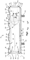
- Fig. 3 is a sectional view of an inflator and a diffuser which form a part of the air bag module of Fig. 1;
- Fig. 4 is a partial sectional view of a portion of an air bag module which is constructed in accordance with a second embodiment of the present invention;
- Fig. 5 is a view, similar to Fig. 3, of an inflator and a diffuser which form a part of an air bag module constructed in accordance with a third embodiment of the present invention;
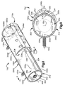
- Fig. 6 is a perspective view of an air bag module constructed in accordance with a fourth embodiment of the present invention;
- Fig. 7 is a sectional view taken generally along line 7-7 of Fig. 6;
- Fig. 8 is a perspective view of an air bag module constructed in accordance with a fifth embodiment of the present invention;
- Fig. 9 is a sectional view taken generally along line 9-9 of Fig. 8;
- Fig. 10 is a perspective view of an air bag module constructed in accordance with a sixth embodiment of the present invention; and
- Fig. 11 is a sectional view taken generally along line 11-11 of Fig. 10.
- The present invention relates to a vehicle safety apparatus, and particularly relates to an air bag module including an inflatable vehicle occupant protection device, such as an air bag, for helping to protect a vehicle occupant in the event of a side impact to the vehicle of a magnitude sufficient to require inflation of the inflatable device. The present invention is applicable to various vehicle safety apparatus constructions. As representative of the present invention, Figs. 1-3 illustrate a vehicle safety apparatus or
air bag module 10. - The air bag module 10 (Fig. 1) is connected with a
seat frame member 12 of aseat 14 for an occupant of a vehicle. Theseat 14 includes aseat bottom cushion 16 and aseatback 18 connected with the seat bottom cushion. A forward direction in the vehicle is indicated by the arrow 20 (Fig. 1) and a rearward direction in the vehicle is indicated by thearrow 22. - The
air bag module 10 includes an inflatable device, illustrated schematically at 30, which is commonly known as an air bag. Theair bag 30 is preferably made from a fabric material such as woven nylon. Theair bag 30 can alternatively be made from a non-woven material, such as plastic film. Theair bag module 10 also includes a cover indicated schematically at 32 (Fig. 2) which encloses the foldedair bag 30. Thecover 32 is opened by the inflatingair bag 30 to enable deployment of the air bag into a position to help protect an occupant of the vehicle seat. Theair bag module 10, including thecover 32, is located within thevehicle seatback 18 underneath the fabric material or leather covering of the seat. - The
air bag module 10 also includes aninflator 40. Theinflator 40 is illustrated as an "augment" type inflator which includes both inflation fluid stored in a container and an ignitable material for heating and thereby increasing the pressure of the inflation fluid. Themodule 10 alternatively could include an inflator which contains only a stored quantity of pressurized inflation fluid, or a pyrotechnic inflator which uses the combustion of gas-generating material to generate inflation fluid in the form of gas to inflate theair bag 30. - As illustrated schematically in Fig. 3, the
inflator 40 includes acontainer 42 which defines aninflation fluid chamber 44. Theinflation fluid chamber 44 contains a stored quantity of pressurizedinflation fluid 46. At one end of theinflation fluid chamber 44 is a rupturable portion of the container or a rupturable member such as aburst disk 48. Anignitable material 50 is disposed within thecontainer 42 at a location adjacent to theinflation fluid chamber 44 for, when ignited, heatinginflation fluid 46 flowing from the inflation fluid chamber. An electricallyactuatable igniter 52, for igniting theignitable material 50 and for opening theinflation fluid chamber 44, is disposed adjacent to the ignitable material. A pair oflead wires 76 extend from acylindrical end portion 74 of theigniter 52. - The
inflator 40 has a generally cylindrical configuration centered on alongitudinal axis 60. Acentral portion 62 of theinflator 40 includes acylindrical side wall 64 of the inflator. Theside wall 64 has a cylindricalouter side surface 66. Thecentral portion 62 of theinflator 40 also includes a plurality offluid outlets 68 which are spaced apart 180° around the circumference of the inflator. - A
first end portion 70 of theinflator 40 has a flat, radially extendingend surface 72. Theend portion 74 of theigniter 52 projects from theend surface 72 of theinflator 40. Asecond end portion 80 of theinflator 40 has a domed configuration including a convexouter surface 82. The convexouter surface 82 of thesecond end portion 80 of theinflator 40 merges with the cylindricalouter surface 66 of thecentral portion 62 of the inflator. Thesecond end portion 80 of the inflator 40 includes one axial end portion (to the left as viewed in Fig. 3) of theinflation fluid chamber 44. - The vehicle in which the
air bag module 10 is mounted includes known means indicated schematically at 90 (Fig. 1) for sensing a side impact to the vehicle and for actuating the inflator 40 in response to the sensing of a side impact. The means 90 may include a side impact sensor and vehicle circuitry for electrically actuating the inflator 40 in response to sensing a side impact to the vehicle above a predetermined threshold. The means 90 is electrically connected with theigniter 52 of the inflator 40, via thelead wires 76, for providing an actuation signal to the inflator. - The
air bag module 10 also includes a diffuser 100 (Figs. 2 and 3) which may also be referred to herein as a retainer assembly or retainer. Thediffuser 100 is made from a single piece of metal and has an elongate, generally cylindrical configuration. Thediffuser 100 includes acentral portion 102, a first end portion 110, and asecond end portion 120. - A
cylindrical side wall 122 of thediffuser 100 extends for the length of thecentral portion 102 of the diffuser. Theside wall 122 is centered on theaxis 60 and has opposite inner and outer side surfaces 124 and 126. Thecentral portion 102 of thediffuser 100, including theside wall 122, is spaced radially outward from the cylindricalouter surface 66 of theinflator 40. - An annular, axially extending,
diffuser chamber 128 is defined between theside wall 122 of thediffuser 100 and the cylindricalouter surface 66 of theinflator 40. A series of circularfluid outlet openings 129 are formed in theside wall 122 of thediffuser 100 and communicate between thediffuser chamber 128 and the exterior of the diffuser. As illustrated, theopenings 129 are aligned in a row centered on a line which extends parallel to thelongitudinal axis 60. A pair of mountingbolts 130 extend radially outward from theside wall 122 of thediffuser 100, opposite thefluid outlet openings 129. - The first end portion 110 of the
diffuser 100 is a clamping portion of the diffuser which is disposed at and supports thefirst end portion 70 of theinflator 40. The first end portion 110 of thediffuser 100 includes afrustoconical wall portion 132 which extends axially away from and radially inward from thecylindrical side wall 122 of the diffuser. Thefrustoconical wall portion 132 engages and supports thefirst end portion 70 of theinflator 40. - The first end portion 110 of the
diffuser 100 also includes a flat,annular wall portion 134 which extends radially inward from thefrustoconical wall portion 132. Thewall portion 134 overlies the radially extendingouter end surface 72 of theinflator 40. Thewall portion 134 has acircular opening 136 which receives the cylindricalouter end portion 74 of theigniter 52. Theopening 136 is preferably larger in diameter than theouter end portion 74 of theigniter 52. Alternatively, theopening 136 may engage and support theouter end portion 74 of theigniter 52. - The
first end portion 70 of the inflator is thus supported on the first end portion 110 of thediffuser 100. By engaging thefirst end portion 70 of the inflator 40, the first end portion 110 of thediffuser 100 blocks radial movement of the first end portion of the inflator relative to the diffuser. The first end portion 110 of thediffuser 100 also blocks axial movement of the inflator 40, relative to the diffuser, in a first axial direction as indicated by thearrow 138, that is to the right as viewed in Fig. 3. The first end portion 110 of thediffuser 100 closes and seals thediffuser chamber 128 at one end, that is, to the right as viewed in Fig. 3. - A
second end portion 120 of thediffuser 100 is a clamping portion of the diffuser which is disposed at and supports thesecond end portion 80 of theinflator 40. Thesecond end portion 120 of thediffuser 100 comprises a curled wall portion orcurl portion 140 of the diffuser. Thesecond end portion 120 is formed as an extension of thecylindrical wall portion 122 of thediffuser 100. Thesecond end portion 120 of the diffuser has a cylindrical configuration as shown in phantom in Fig. 3 prior to assembly of theair bag module 100. Thesecond end portion 120 of thediffuser 100 is movable from the cylindrical condition shown in phantom in Fig. 3 to the curled condition shown in solid lines in Fig. 3 during assembly of theair bag module 10. - The
curl portion 140 has an arcuate cross-sectional configuration centered on acircular bending axis 141, as seen in Fig. 3. Thecurl portion 140 of thediffuser 100 extends radially inward from thecylindrical side wall 122 at a plurality of locations which are disposed in a circular array which is centered on theaxis 60. In the preferred embodiment, thecurl portion 140 of thediffuser 100 extends radially inward from thecylindrical side wall 122, in a uniform manner, for 360° around theaxis 60. Thecurl portion 140 defines acircular opening 142 which receives thesecond end portion 80 of theinflator 40. Aninner side surface 146 of thecurl portion 140 extends as a continuation of theinner side surface 124 of thecylindrical side wall 122 of thediffuser 100. - An
outer side surface 150 of thecurl portion 140 extends as a continuation of theouter side surface 126 of thecylindrical side wall 122 of thediffuser 100. Theouter side surface 150 of thecurl portion 140 engages the convexouter surface 82 of the domedsecond end portion 80 of theinflator 40. This engagement occurs along a circular area or line ofengagement 154 extending around and centered on theaxis 60, in a uniform manner for 360° around the axis. That is, thecurl portion 140 of thediffuser 100 engages and supports the inflator 40 at a plurality or series of locations which are disposed in a circular array extending around theaxis 60. - The
second end portion 120 of thediffuser 100 closes and seals thediffuser chamber 128 at one end, that is, to the left as viewed in Fig. 3. Thesecond end portion 120 of thediffuser 100 blocks axial movement of the inflator 40, relative to the diffuser, in a second axial direction as indicated by thearrow 158, that is, to the left as viewed in Fig. 3. Thesecond end portion 120 of thediffuser 100 also blocks radial movement of thesecond end portion 80 of the inflator 40, relative to the diffuser. - The inflator 40 is inserted into the
diffuser 100 when the diffuser has a completely cylindrical configuration, that is, when theend portions 110 and 120 of the diffuser are not yet bent radially inward from thecylindrical side wall 122. The first end portion 110 of thediffuser 100 is then deformed inward into engagement with thefirst end portion 70 of theinflator 40. Thesecond end portion 120 of thediffuser 100 is then curled into engagement with thesecond end portion 80 of theinflator 40. The inflator 40 is clamped in thediffuser 100 with an axially directed force in the range of from about 80 pounds to about 300 pounds. The inflator 40 engages, or is connected with, thediffuser 100 only at theend portions 110 and 120 of the diffuser; there is no other connection or engagement between the inflator and the diffuser. - The assembly of the inflator 40 and the
diffuser 100 is then inserted into theair bag 30 and thecover 32. The mountingbolts 130 extend through fastener openings in theair bag 30 and thecover 32. Thelead wires 76 extend out of theair bag 30 through another opening (not shown) in the air bag. - A pair of nuts 160 secure a mounting
bracket 162 on the mountingbolts 130. The mountingbracket 162 is then secured byfasteners 164 to theseat frame member 12 in theseatback 18. Themodule 10 is preferably mounted on theseatback 18 so that when the seatback is reclined at an angle of 25° from the vertical and the inflator 40 is actuated, theair bag 30 deploys in a generally forward and upward direction as illustrated in Fig. 1. - In the event of a side impact to the vehicle of a magnitude for which inflation of the
air bag 30 is desired to help protect the vehicle occupant, theigniter 52 is actuated. Theignitable material 50 ignites and theburst disk 48 ruptures. Theinflation fluid 46 flows out of thecontainer 42, past theignitable material 50. As theinflation fluid 46 flows past theignitable material 50, the inflation fluid is heated and its pressure increases. Theinflation fluid 46 flows out of the inflator 40, through thefluid outlets 68 in the inflator, and into thediffuser chamber 128. Theinflation fluid 46 flows out of thediffuser chamber 128, through theopenings 129 in thediffuser 100, and into theair bag 30. The rapidly flowing inflation fluid causes theair bag 30 to cut through the portions of theseatback 18 which overlie themodule 10, such as foam cushion material and/or fabric material or leather covering of the seat. Theair bag 30 inflates from a folded, stored condition to an inflated condition as illustrated in Fig. 1. - Fig. 4 illustrates a portion of an
air bag module 10a which is constructed in accordance with a second embodiment of the present invention. Parts of theair bag module 10a which are the same as or similar to corresponding parts of themodule 10 are given the same reference numeral with the suffix "a" added for clarity. - The
air bag module 10a includes aninflator 40a which is the same as the inflator 40 (Figs. 1-3). Themodule 10a includes a retainer ordiffuser 100a, which may also be referred to herein as a retainer, which is generally similar to the diffuser 100 (Figs. 1-3). In thediffuser 100a, however, thecurl portion 140a does not engage the domedsecond end portion 80a of theinflator 40a. Instead, acushion 170 is disposed between thecurl portion 140a of thediffuser 100a and thesecond end portion 80a of theinflator 40a. Thecushion 170 and thediffuser 100a together form a retainer assembly of theair bag module 10a. - The
cushion 170 is made from a compressible material such as rubber or plastic and includes a generally hemisphericalmain body portion 172. Themain body portion 172 of thecushion 170 is closely fitted around thedomed end portion 80a of theinflator 40a. Themain body portion 172 of thecushion 170 has a generally hemisphericalouter side surface 174. - A plurality of
ribs 176 project radially outward from theouter side surface 174 of themain body portion 172 of thecushion 170. Theribs 176 engage theinner side surface 124a of the cylindrical wall portion 122a of thediffuser 100a. The engagement of theribs 176 with thediffuser 100a maintains thesecond end portion 80a of theinflator 40a at a position centered on theaxis 60a. - The
curl portion 140a of thediffuser 100a engages theouter side surface 174 of themain body portion 172 of thecushion 170. Anannular edge 180 of thecurl portion 140a extends into the material of themain body portion 172 of thecushion 170 and clamps the cushion against thesecond end portion 80a of theinflator 40a. Thecushion 170 blocks metal to metal contact between the second end portion 120a of thediffuser 100a and thesecond end portion 80a of theinflator 40a. - Fig. 5 illustrates a portion of an
air bag module 10b which is constructed in accordance with a third embodiment of the present invention. Parts of theair bag module 10b which are the same as or similar to corresponding parts of the modules 10 (Figs. 1-3) or 10a (Fig. 4) are given the same reference numeral with the suffix "b" added for clarity. - The
air bag module 10b includes an inflator 40b which is the same as the inflator 40 (Figs. 1-3). Themodule 10b includes a retainer ordiffuser 100b which is generally similar to the diffuser 100 (Figs. 1-3). - A
second end portion 120b of thediffuser 100b is disposed at and supports thesecond end portion 80b of the inflator 40b. Thesecond end portion 120b of thediffuser 100b comprises a radial formed wall portion orradial portion 140b of the diffuser. Thesecond end portion 120b is formed as an extension of thecylindrical wall portion 122b of thediffuser 100b. Thesecond end portion 120b of the diffuser has a cylindrical configuration, shown in phantom in Fig. 5, prior to assembly of theair bag module 100b. Thesecond end portion 120b of thediffuser 100b is movable from the cylindrical condition to the condition shown in solid lines in Fig. 5 during assembly of theair bag module 10b. - The
radial portion 140b of thediffuser 100b is similar to thecurl portion 140 of the diffuser 100 (Figs. 1-3) with the exception that the radial portion does not curl axially toward the first end portion 110b of the diffuser. Specifically, theradial portion 140b of thediffuser 100b extends radially inward from thecylindrical side wall 122b at least at a plurality of locations which are disposed in a circular array which is centered on theaxis 60b. In the preferred embodiment, theradial portion 140b of thediffuser 100b has an arcuate orhemispherical wall portion 190b which extends radially inward from thecylindrical side wall 122b, in a uniform manner, for 360° around theaxis 60b. Theradial portion 140b could, alternatively, be a series of discrete sections in a circular array. Thearcuate wall portion 190b of theradial portion 140b of thediffuser 100b terminates in an annular, radially extendinginner wall portion 192b. - A
cushion 170b is disposed between theradial portion 140b of thediffuser 100b and thesecond end portion 80b of the inflator 40b. Thecushion 170b and thediffuser 100b together form a retainer assembly of theair bag module 10b. Thecushion 170b includes a generally hemisphericalmain body portion 172b which is closely fitted around thedomed end portion 80b of the inflator 40b. Themain body portion 172b of thecushion 170b has a generally hemisphericalouter side surface 174b when in an undeformed condition (not shown). - The
radial portion 140b of thediffuser 100b engages theouter side surface 174b of themain body portion 172b of thecushion 170b. Anannular edge 194b of theradial portion 140b compresses the material of themain body portion 172b of thecushion 170b and clamps the cushion against thesecond end portion 80b of the inflator 40b. Thecushion 170b blocks metal to metal contact between thesecond end portion 120b of thediffuser 100b and thesecond end portion 80b of the inflator 40b. - Figs. 6 and 7 illustrate portions of an
air bag module 10c which is constructed in accordance with a fourth embodiment of the present invention. Theair bag module 10c may be substituted for theair bag module 10, in the vehicle seat 14 (Fig. 1). - The
air bag module 10c (Figs. 6 and 7) includes anelongate inflator 40c. The inflator 40c includes acylindrical body portion 200 having a cylindricalouter surface 202 centered on anaxis 60c of the inflator. Acylindrical neck portion 204 of the inflator 40c projects from thebody portion 200 at afirst end portion 206 of the inflator. Theneck portion 204 is smaller in diameter than thebody portion 200. Theneck portion 204 includes a plurality ofinflation fluid outlets 208. Anelectrical connector 210 is located at a second end portion 212 of the inflator 40c. - The
module 10b includes atubular retainer assembly 220 for securing the inflator 40c in position relative to theseat member 12 of thevehicle seat 14. Theretainer assembly 220 includes a tubular diffuser orretainer 100c formed from one piece of sheet metal stamped and formed to the generally cylindrical configuration shown in Fig. 6. A pair of externally threadedweld studs 130c are secured to theretainer 100c along animaginary baseline 222 of the retainer. - The
retainer 100c includes first andsecond side walls baseline 222. Thefirst side wall 230 has acylindrical portion 232 which extends about 90° around the circumference of theretainer 100b in a direction away from thebaseline 222. Thecylindrical portion 232 of thefirst side wall 230 has a cylindricalinner surface 234. - The
second side wall 240 has acylindrical portion 242 which extends about 90° around the circumference of theretainer 100b in a direction away from thebaseline 222. Thecylindrical portion 242 of thesecond side wall 240 has a cylindricalinner surface 244 which is presented toward the cylindricalinner surface 234 of thefirst side wall 230. The side wallinner surfaces outer side surface 202 of thebody portion 200 of the inflator 40c. - From the
cylindrical portions side walls inner surfaces Arcuate end portions side walls seam 248 diametrically opposite thebaseline 222. Theseam 248 may be spot welded or otherwise secured. Theend portions side walls retainer 100c have a plurality ofopenings 249 for enabling flow of inflation fluid out of the retainer. - A
planar end wall 250 of theretainer 100c is folded about ahinge portion 252 to an orientation generally perpendicular to theaxis 60c. Theend wall 250 at least partially closes thefirst end portion 110c of theretainer 100c. Theside walls end wall 250 define adiffuser chamber 252 inside theretainer 100c. Thesecond end portion 120c of theretainer 100c is open to enable electrical connection with the inflator 40c. - A
first clamping portion 260 of theretainer 100c includes a pair of first retainingtabs side walls second clamping portion 270 of theretainer 100c includes a pair ofsecond retaining tabs side walls first retaining tabs retainer 100c from thesecond retaining tabs - Each one of the retaining
tabs retainer 100c. Each one of the retainingtabs retainer 100c along three sides of a rectangular area. The retainingtabs baseline 222 of theretainer 100c. - The inflator 40c is inserted axially into the
diffuser chamber 252 in theretainer 100c. The four retainingtabs outer surface 202 of thebody portion 200 of the inflator 40c, at locations spaced axially along the length of the inflator. The retainingtabs cylindrical body portion 200 of the inflator 40c into mating engagement with the cylindrical inner side surfaces 234 and 244 of theside walls retainer 100c. - The
first retaining tabs retainer 100c engage a firstouter surface portion 280 of the inflator 40c to block radial and axial movement of the first outer surface portion of the inflator. Thesecond retaining tabs retainer 100c engage a secondouter surface portion 282 of the inflator 40c, spaced axially from the firstouter surface portion 280, to block radial and axial movement of the second outer surface portion of the inflator. The force of the retainingtabs retainer 100c, is sufficient to hold the inflator in position relative to the inflator. There are no fasteners, such as bolts or welds, extending between theretainer 100c and the inflator 40c. - Figs. 8 and 9 illustrate portions of an
air bag module 10d which is constructed in accordance with a fifth embodiment of the invention. Theair bag module 10d includes aninflator 40d which is identical to the inflator 40c (Figs. 6 and 7). Themodule 10d includes aretainer assembly 220d which includes a diffuser orretainer 100d for securing theinflator 40d in position relative to theseat member 12 of thevehicle seat 14. - The
retainer 100d, for about half of its length, has a configuration similar to the configuration of theretainer 100c (Figs. 6 and 7). The remaining length of theretainer 100d includes twoside wall portions body portion 200d of theinflator 40d is press fitted. Each one of theside wall portions retainer 100d extends 180° circumferentially in a direction away from thebaseline 222d of the retainer. - The
side wall portions inner surfaces inner surfaces outer side surface 202d of thebody portion 200d of theinflator 40d.End portions side walls seam 330 which is diametrically opposite thebaseline 222d. Theseam 330 may be spot welded or otherwise secured. - The
inflator 40d is inserted axially into theretainer 100d. Thebody portion 200d of theinflator 40d has a press fit within the interconnectedside wall portions retainer 100d. Theside wall portions retainer 100d are in clamping engagement with theouter side surface 202d of thebody portion 200d of theinflator 40d, at a plurality of locations spaced axially along the length of the inflator. Specifically, afirst clamping portion 332 of theretainer 100d, including apart 332a of thefirst side wall 300 and apart 332b of thesecond side wall 310, engages a firstouter surface portion 334 of the inflator 40d to block radial and axial movement of the first outer surface portion of the inflator. Asecond clamping portion 336 of theretainer 100d, including apart 336a of thefirst side wall 300 and apart 336b of thesecond side wall 310, engages a secondouter surface portion 338 of the inflator 40d to block radial and axial movement of the second outer surface portion of the inflator. The secondouter surface portion 338 of theinflator 40d is spaced apart axially from the firstouter surface portion 334 of the inflator. - The force of the
side wall portions inflator 40d within theretainer 100d, is sufficient to hold the inflator in position relative to the inflator. There are no fasteners, such as bolts or welds, extending between theretainer 100d and theinflator 40d. - Figs. 10 and 11 illustrate portions of an
air bag module 10e which is constructed in accordance with a sixth embodiment of the invention. Theair bag module 10e includes aninflator 40e which is identical to the inflator 40c (Figs. 6 and 7). Themodule 10e includes atubular retainer assembly 220e which includes a tubular diffuser orretainer 100e for securing theinflator 40e in position relative to theseat member 12 of thevehicle seat 14. - The
retainer 100e has a configuration similar to the configuration of theretainer 100d (Figs. 8 and 9). In theretainer 100e, however, theside wall portions body portion 200e of theinflator 40e. Rather, each one of theside wall portions body portion 200e of theinflator 40e. Outwardly flaredend portions side wall portions gap 340. - The
side wall portions inner surfaces inner surfaces side wall portions outer side surface 202e of thebody portion 200e of theinflator 40e. - The
retainer 100e is formed with theside wall portions side wall portions retainer 100b, to a position as shown in solid lines in Fig. 11. - The
inflator 40e is inserted into theretainer 100e through thegap 340 between theend portions side wall portions body portion 200e of theinflator 40e forces theside wall portions retainer 100e radially outward. Theside wall portions retainer 100e snap into place against theouter side surface 202e of thebody portion 200e of theinflator 40e when the inflator moves into the position shown in Figs. 10 and 11 coaxial with the retainer. - The
side wall portions retainer 100e are in clamping engagement with theouter side surface 202e of thebody portion 200e of theinflator 40e, at a plurality of locations spaced axially along the length of the inflator. Specifically, afirst clamping portion 342 of theretainer 100e, including apart 342a of thefirst side wall 300e and apart 342b of thesecond side wall 310e, engages a firstouter surface portion 344 of the inflator 40e to block radial and axial movement of the first outer surface portion of the inflator. Asecond clamping portion 346 of theretainer 100e, including apart 346a of thefirst side wall 300e and apart 346b of thesecond side wall 310e, engages a secondouter surface portion 348 of the inflator 40e to block radial and axial movement of the secondouter surface portion 344 of the inflator. The secondouter surface portion 348 of theinflator 40e is spaced apart axially from the firstouter surface portion 344 of the inflator. The force of theside wall portions inflator 40e within theretainer 100e, is sufficient to hold the inflator in position relative to the inflator. There are no fasteners, such as bolts or welds, extending between theretainer 100e and theinflator 40e. - From the above description of the invention, those skilled in the art will perceive improvements, changes and modifications in the invention. For example, the second end portion of the diffuser need not have the curled configuration shown in Figs. 3 and 5, but instead may have a different configuration, such as one similar to the configuration of the first end portion 110 of the
diffuser 100. Thus, the second end portion of the diffuser may comprise one or more wall portions which extend radially inward, and perhaps axially in a direction away from the first end portion of the diffuser, but not axially in a direction toward the first end portion of the diffuser. Also, the first end portion of the diffuser could have a curled configuration similar to the configuration of thesecond end portion 120 of thediffuser 100. In either case, the inflator would still be clamped axially, between the diffuser end portions, with a force of from about 80 pounds to about 300 pounds. Further, a member such as thecushion 170 could be provided between the first end portion of the inflator and the first end portion of the diffuser, particularly if the first end portion of the inflator has a domed or non-flat configuration. Such improvements, changes and modifications within the skill of the art are intended to be covered by the appended claims. - It should be noted that the objects and advantages of the invention may be attained by means of any compatible combination(s) particularly pointed out in the items of the following summary of the invention and the appended claims.
-
- 1. A vehicle safety apparatus for helping to protect an occupant of a vehicle in the event of an impact to the vehicle, said apparatus comprising:
- an inflatable occupant protection device having a deflated condition and being inflatable into a position adjacent to the vehicle occupant for helping to protect the vehicle occupant;
- an inflator which is actuatable to provide inflation fluid for inflating said inflatable device, said inflator having a longitudinal axis, a first end portion, a second end portion, and a central portion between said first and second end portions;
- a diffuser receiving said inflator, said diffuser having a central wall portion and first and second opposite end portions;
- means for supporting said diffuser and said inflator on the vehicle;
- said central wall portion of said diffuser being spaced radially outward from said central portion of said inflator to define a diffuser chamber between said central wall portion of said diffuser and said central portion of said inflator;
- said first end portion of said diffuser extending radially inward from said central wall portion of said diffuser and blocking axial movement of said inflator in a first axial direction; and
- said second end portion of said diffuser having a curl portion extending radially inward from said central wall portion of said diffuser in a direction toward said longitudinal axis and toward said first end portion of said diffuser, said curl portion of said diffuser blocking radial movement of said second end portion of said inflator and blocking axial movement of said inflator in a second axial direction opposite to said first axial direction.
- 2. An apparatus wherein said curl portion of said diffuser comprises a cylindrical wall portion of said diffuser which is curled radially inward and axially in a direction toward said first end portion of said diffuser about a circular bending axis which is centered on said longitudinal axis.
- 3. An apparatus wherein said curl portion of said diffuser has an inner side surface and an opposite outer side surface, said curl portion of said diffuser comprising a cylindrical wall portion which is deformed radially inwardly by more than 90° at a plurality of locations centered on said longitudinal axis so that said outer side surface of said curl portion is presented in a direction toward said longitudinal axis.
- 4. An apparatus wherein said inflator comprises a container having an inflation fluid chamber in which inflation fluid is stored under pressure, an ignitable material for, when ignited, heating said inflation fluid, and ignition means for igniting said ignitable material and for opening said container, said inflator including at least one fluid outlet for directing heated inflation fluid from said inflator into said diffuser chamber.
- 5. An apparatus wherein said curl portion of said diffuser engages said second end portion of said inflator to block radial and axial movement of said second end portion of said inflator.
- 6. An apparatus wherein said curl portion of said diffuser is spaced apart from said second end portion of said inflator, said apparatus further comprising a cushion disposed intermediate said curl portion of said diffuser and said second end portion of said inflator, said curl portion of said diffuser clamping said cushion against said second end portion of said inflator to block radial and axial movement of said second end portion of said inflator.
- 7. A vehicle safety apparatus for heaping to protect an occupant of a vehicle seat in the event of a side impact to the vehicle, said apparatus comprising:
- an inflatable occupant protection device having a deflated condition and being inflatable into a position between the side structure of the vehicle and the vehicle occupant for helping to protect the vehicle occupant;
- an inflator which is actuatable to provide inflation fluid for inflating said inflatable device, said inflator having a longitudinal axis, a first end portion, a second end portion, and a central portion between said first and second end portions;
- a diffuser receiving said inflator, said diffuser having a central wall portion and first and second opposite end portions;
- means for connecting said diffuser and said inflator with the vehicle seat;
- said central wall portion of said diffuser being spaced radially outward from said central portion of said inflator to define a diffuser chamber between said central wall portion of said diffuser and said central portion of said inflator;
- said first end portion of said diffuser extending radially inward from said central wall portion of said diffuser and blocking axial movement of said inflator in a first axial direction; and
- said second end portion of said diffuser having a curl portion extending radially inward from said central wall portion of said diffuser in a direction toward said longitudinal axis and toward said first end portion of said diffuser, said curl portion of said diffuser blocking radial movement of said second end portion of said inflator and blocking axial movement of said inflator in a second axial direction opposite to said first axial direction.
- 8. An apparatus wherein said central wall portion of said diffuser comprises a cylindrical wall having a cylindrical inner surface;
said central portion of said inflator having a cylindrical outer surface which is spaced radially inward from said cylindrical inner surface of said diffuser and having at least one fluid outlet for directing inflation fluid from said inflator into said diffuser chamber;
said central wall section of said diffuser having a plurality of openings for directing inflation fluid from said diffuser chamber into said inflatable device. - 9. An apparatus wherein said curl portion of said diffuser comprises a cylindrical wall portion of said diffuser which is curled radially inward and axially in a direction toward said first end portion of said diffuser about a circular bending axis which is centered on said longitudinal axis.
- 10. An apparatus wherein said curl portion of said diffuser has an inner side surface and an opposite outer side surface, said curl portion of said diffuser comprising a cylindrical wall portion which is deformed radially inwardly by more than 90° at a plurality of locations centered on said longitudinal axis so that said outer side surface of said curl portion is presented in a direction toward said longitudinal axis.
- 11. An apparatus wherein said inflator comprises a container having an inflation fluid chamber in which inflation fluid is stored under pressure, an ignitable material for, when ignited, heating said inflation fluid, and ignition means for igniting said ignitable material and for opening said container, said inflator including at least one fluid outlet for directing heated inflation fluid from said inflator into said diffuser chamber.
- 12. An apparatus wherein said curl portion of said diffuser engages said second end portion of said inflator to block radial and axial movement of said second end portion of said inflator.
- 13. An apparatus wherein said second end portion of said inflator has a domed configuration including a convex outer surface which is presented toward said curl portion of said diffuser, said curl portion of said diffuser engaging said convex outer surface at a plurality of locations in a circular array extending around said longitudinal axis.
- 14. An apparatus wherein said curl portion of said diffuser is spaced apart from said second end portion of said inflator, said apparatus further comprising a cushion disposed intermediate said curl portion of said diffuser and said second end portion of said inflator, said curl portion of said diffuser clamping said cushion against said second end portion of said inflator to block radial and axial movement of said second end portion of said inflator.
- 15. A vehicle safety apparatus for helping to protect an occupant of a vehicle seat in the event of a side impact to the vehicle, said apparatus comprising:
- an inflatable occupant protection device having a deflated condition and being inflatable into a position between the side structure of the vehicle and the vehicle occupant for helping to protect the vehicle occupant;
- an elongate, cylindrical inflator which is actuatable to provide inflation fluid for inflating said inflatable device, said inflator having an axis, a first end portion, a second end portion, and a central portion between said first and second end portions;
- an elongate, cylindrical diffuser receiving said inflator, said diffuser having a central wall portion and first and second opposite end portions; and
- means for connecting said diffuser and said inflator with the vehicle seat;
- said central wall portion of said diffuser being spaced radially outward from said central portion of said inflator to define a diffuser chamber between said central wall portion of said diffuser and said central portion of said inflator;
- said inflator comprising a container having a chamber in which inflation fluid is stored under pressure, an ignitable material for, when ignited, heating said inflation fluid, and ignition means for igniting said ignitable material and for opening said container, said inflator including at least one fluid outlet for directing heated inflation fluid from said inflator into said diffuser chamber;
- said central wall portion of said diffuser having a plurality of openings for directing inflation fluid from said diffuser chamber into said inflatable device;
- said first end portion of said diffuser extending radially inward from said central wall portion of said diffuser and blocking axial movement of said inflator in a first axial direction;
- said second end portion of said diffuser having a curl portion extending radially inward from said central wall portion of said diffuser in a direction toward said axis and toward said first end portion of said diffuser, said curl portion of said diffuser blocking radial movement of said second end portion of said inflator and blocking axial movement of said inflator in a second axial direction opposite to said first axial direction.
- 16. An apparatus wherein said second end portion of said inflator has a domed configuration including a convex outer surface which is presented toward said curl portion of said diffuser.
- 17. An apparatus wherein said curl portion of said diffuser is spaced apart from said second end portion of said inflator, said apparatus further comprising a cushion disposed intermediate said curl portion of said diffuser and said second end portion of said inflator, said curl portion of said diffuser clamping said cushion against said second end portion of said inflator to block radial and axial movement of said second end portion of said inflator.
- 18. An apparatus wherein said inflator is clamped axially between said cushion and said first end portion of said diffuser, said inflator being free of other connections with said diffuser.
- 19. An apparatus wherein said curl portion of said diffuser engages said second end portion of said inflator.
- 20. An apparatus wherein said inflator is clamped axially between said curl portion and said first end portion of said diffuser, said inflator being free of other connections with said diffuser.
- 21. An apparatus wherein said curl portion of said diffuser comprises a cylindrical wall portion of said diffuser which is curled radially inward and axially in a direction toward said first end portion of said diffuser about a circular bending axis which is centered on said longitudinal axis.
- 22. An apparatus wherein said curl portion of said diffuser has an inner side surface and an opposite outer side surface, said curl portion of said diffuser comprising a cylindrical wall portion which is deformed radially inwardly by more than 90° at a plurality of locations centered on said longitudinal axis so that said outer side surface of said curl portion is presented in a direction toward said longitudinal axis.
- 23. A vehicle safety apparatus for heaping to protect an occupant of a vehicle seat in the event of a side impact to the vehicle, said apparatus comprising:
- an inflatable occupant protection device having a deflated condition and being inflatable into a position between the side structure of the vehicle and the vehicle occupant for helping to protect the vehicle occupant;
- an inflator which is actuatable to provide inflation fluid for inflating said inflatable device, said inflator having a longitudinal axis, a first end portion, a second end portion, and a central portion between said first and second end portions;
- a diffuser receiving said inflator, said diffuser having a central wall portion and first and second opposite end portions;
- means for connecting said diffuser and said inflator with the vehicle seat;
- said central wall portion of said diffuser being spaced radially outward from said central portion of said inflator to define a diffuser chamber between said central wall portion of said diffuser and said central portion of said inflator;
- said first end portion of said diffuser extending radially inward from said central wall portion of said diffuser and blocking axial movement of said inflator in a first axial direction; and
- said second end portion of said diffuser extending radially inward from said central wall portion of said diffuser in a direction toward said longitudinal axis, said second end portion of said diffuser blocking axial movement of said inflator in a second axial direction opposite to said first axial direction;
- said first and second end portions of said diffuser exerting an axial clamping force on said inflator in the range of from about 80 pounds to about 300 pounds.
- 24. An apparatus wherein said second end portion of said diffuser comprises a wall portion of said diffuser which is curled radially inward and axially in a direction toward said first end portion of said diffuser.
- 25. A vehicle safety apparatus for helping to protect an occupant of a vehicle in the event of an impact to the vehicle, said apparatus comprising:
- an inflatable occupant protection device having a deflated condition and being inflatable into a position adjacent to the vehicle occupant for helping to protect the vehicle occupant;
- an inflator which is actuatable to provide inflation fluid for inflating said inflatable device, said inflator having a longitudinal axis, a first end portion, a second end portion, and a central portion between said first and second end portions;
- a diffuser receiving said inflator, said diffuser having a central wall portion and first and second opposite end portions;
- means for supporting said diffuser and said inflator on the vehicle;
- said central wall portion of said diffuser being spaced radially outward from said central portion of said inflator to define a diffuser chamber between said central wall portion of said diffuser and said central portion of said inflator;
- said first end portion of said diffuser extending radially inward from said central wall portion of said diffuser and blocking axial movement of said inflator in a first axial direction; and
- said second end portion of said diffuser having a radial portion extending radially inward from said central wall portion of said diffuser in a direction toward said longitudinal axis, said radial portion of said diffuser blocking radial movement of said second end portion of said inflator and blocking axial movement of said inflator in a second axial direction opposite to said first axial direction.
- 26. An apparatus wherein said radial portion of said diffuser comprises a cylindrical wall portion of said diffuser which has an arcuate portion extending radially inward from said central wall portion of said diffuser.
- 27. An apparatus wherein said arcuate portion of said radial portion of said diffuser does not extend axially in a direction toward said first end portion of said diffuser.
- 28. An apparatus wherein said radial portion of said diffuser is spaced apart from said second end portion of said inflator, said apparatus further comprising a cushion disposed intermediate said radial portion of said diffuser and said second end portion of said inflator, said radial portion of said diffuser clamping said cushion against said second end portion of said inflator to block radial and axial movement of said second end portion of said inflator.
- 29. An apparatus wherein said cushion is made from a compressible material.
- 30. An apparatus wherein said inflator is clamped axially between said cushion and said first end portion of said diffuser, said inflator being free of other connections with said diffuser.
- 31. An air bag module comprising:
- an elongate inflator having first and second axially spaced outer surface portions;
- a tubular retainer assembly at least partially enclosing said inflator; and
- means for securing said inflator and said retainer assembly together, consisting of (a) a first clamping portion of said tubular retainer assembly engaging said first outer surface portion of said inflator and blocking movement of said first outer surface portion of said inflator relative to said tubular retainer assembly, and (b) a second clamping portion of said tubular retainer assembly engaging said second outer surface portion of said inflator and blocking movement of said second outer surface portion of said inflator relative to said tubular retainer assembly.
- 32. An air bag module
wherein said retainer assembly comprises a tubular metal retainer having at least one opening for enabling flow of inflation fluid out of said retainer assembly;
said first clamping portion of said retainer assembly including a compressible cushion disposed intermediate said tubular metal retainer and said first outer surface portion of said inflator, said tubular metal retainer clamping said cushion against said first outer surface portion of said inflator. - 33. An air bag module
wherein said retainer assembly consists essentially of a tubular metal retainer having at least one opening for enabling flow of inflation fluid out of said retainer assembly. - 34. An air bag module
wherein said inflator has a body portion having a cylindrical outer surface which extends for substantially the entire length of said body portion of said inflator, said first outer surface portion of said inflator comprising an engagement surface on said inflator disposed radially inward of said cylindrical outer surface of said body portion of said inflator, said first clamping portion of said tubular retainer assembly extending radially inward of said cylindrical outer surface and engaging said engagement surface on said inflator. - 35. An air bag module
wherein said inflator has an end portion and said engagement surface on said inflator is on an end portion of said inflator. - 36. An air bag module
wherein said first clamping portion of said tubular retainer assembly has a curl portion extending radially inward in a direction toward a longitudinal axis of said inflator and toward said second clamping portion of said tubular retainer assembly, said curl portion blocking movement of said first outer surface portion of said inflator relative to said tubular retainer assembly. - 37. An air bag module
wherein said curl portion comprises a cylindrical wall portion of said tubular member which is curled radially inward and axially in a direction toward said second clamping portion of said tubular retainer assembly about a circular bending axis which is centered on said longitudinal axis. - 38. An air bag module
wherein said first clamping portion of said tubular retainer assembly comprises a radial wall portion extending radially inward from a central wall portion of said tubular retainer assembly in a direction toward a longitudinal axis of said inflator. - 39. An apparatus wherein said radial portion of said tubular retainer assembly comprises a cylindrical wall portion of said tubular retainer assembly which has an arcuate portion extending radially inward from said central wall portion of said tubular retainer assembly, and wherein said arcuate portion of said radial portion of said tubular retainer assembly does not extend axially in a direction toward said second clamping portion of said tubular retainer assembly.
- 40. An apparatus wherein said tubular retainer assembly comprises a tubular member having a generally cylindrical wall portion, said first and second clamping portions of said tubular retainer assembly being spaced apart along the length of said tubular member and extending radially inward from said generally cylindrical wall portion into engagement with said first and second outer surface portions of said inflator.
- 41. An apparatus wherein said first and second clamping portions comprise relatively small parts of said generally cylindrical wall portion which are deformed inward from said generally cylindrical wall portion into engagement with said first and second outer surface portions of said inflator.
- 42. An air bag module
wherein each one of said clamping portions includes at least two circumferentially spaced small parts of said generally cylindrical wall portion which are deformed inward from said generally cylindrical wall portion into engagement with said first and second outer surface portions of said inflator. - 43. An apparatus wherein said first and second clamping portions of said tubular retainer assembly are axially spaced parts of cylindrical wall portions of said tubular retainer assembly which encircle said inflator for more than 180 degrees along a portion of the length of the inflator.
- 44. An apparatus wherein said cylindrical wall portions of said tubular retainer assembly encircle said inflator for 360 degrees along a portion of the length of the inflator.
- 45. An apparatus wherein said inflator is press fitted in said tubular retainer assembly.
- 46. An apparatus wherein said inflator is clipped in said tubular retainer assembly by resilient wall portions of said tubular retainer assembly which include said first and second clamping portions.
Claims (30)
- A vehicle safety apparatus for helping to protect an occupant of a vehicle in the event of an impact to the vehicle, said apparatus comprising:an inflatable occupant protection device having a deflated condition and being inflatable into a position adjacent to the vehicle occupant for helping to protect the vehicle occupant;an inflator which is actuatable to provide inflation fluid for inflating said inflatable device, said inflator having a longitudinal axis, a first end portion, a second end portion, and a central portion between said first and second end portions;a diffuser receiving said inflator, said diffuser having a central wall portion and first and second opposite end portions;means for supporting said diffuser and said inflator on the vehicle;said central wall portion of said diffuser being spaced radially outward from said central portion of said inflator to define a diffuser chamber between said central wall portion of said diffuser and said central portion of said inflator;said first end portion of said diffuser extending radially inward from said central wall portion of said diffuser and blocking axial movement of said inflator in a first axial direction; andsaid second end portion of said diffuser having a curl portion extending radially inward from said central wall portion of said diffuser in a direction toward said longitudinal axis and toward said first end portion of said diffuser, said curl portion of said diffuser blocking radial movement of said second end portion of said inflator and blocking axial movement of said inflator in a second axial direction opposite to said first axial direction.
- A vehicle safety apparatus for heaping to protect an occupant of a vehicle seat in the event of a side impact to the vehicle, said apparatus comprising:an inflatable occupant protection device having a deflated condition and being inflatable into a position between the side structure of the vehicle and the vehicleoccupant for helping to protect the vehicle occupant; an inflator which is actuatable to provide inflation fluid for inflating said inflatable device, said inflator having a longitudinal axis, a first end portion, a second end portion, and a central portion between said first and second end portions;a diffuser receiving said inflator, said diffuser having a central wall portion and first and second opposite end portions;means for connecting said diffuser and said inflator with the vehicle seat;said central wall portion of said diffuser being spaced radially outward from said central portion of said inflator to define a diffuser chamber between said central wall portion of said diffuser and said central portion of said inflator;said first end portion of said diffuser extending radially inward from said central wall portion of said diffuser and blocking axial movement of said inflator in a first axial direction; andsaid second end portion of said diffuser having a curl portion extending radially inward from said central wall portion of said diffuser in a direction toward said longitudinal axis and toward said first end portion of said diffuser, said curl portion of said diffuser blocking radial movement of said second end portion of said inflator and blocking axial movement of said inflator in a second axial direction opposite to said first axial direction.
- An apparatus as set forth in claim 2 wherein said central wall portion of said diffuser comprises a cylindrical wall having a cylindrical inner surface;
said central portion of said inflator having a cylindrical outer surface which is spaced radially inward from said cylindrical inner surface of said diffuser and having at least one fluid outlet for directing inflation fluid from said inflator into said diffuser chamber;
said central wall section of said diffuser having a plurality of openings for directing inflation fluid from said diffuser chamber into said inflatable device. - An apparatus as set forth in one or more claims wherein said curl portion of said diffuser comprises a cylindrical wall portion of said diffuser which is curled radially inward and axially in a direction toward said first end portion of said diffuser about a circular bending axis which is centered on said longitudinal axis.
- An apparatus as set forth in one or more claims wherein said curl portion of said diffuser has an inner side surface and an opposite outer side surface, said curl portion of said diffuser comprising a cylindrical wall portion which is deformed radially inwardly by more than 90° at a plurality of locations centered on said longitudinal axis so that said outer aide surface of said curl portion is presented in a direction toward said longitudinal axis.
- An apparatus as set forth in one or more claims wherein said inflator comprises a container having an inflation fluid chamber in which inflation fluid is stored under pressure, an ignitable material for, when ignited, heating said inflation fluid, and ignition means for igniting said ignitable material and for opening said container, said inflator including at least one fluid outlet for directing heated inflation fluid from said inflator into said diffuser chamber.
- An apparatus as set forth in one or more claims wherein said curl portion of said diffuser engages said second end portion of said inflator to block radial and axial movement of said second end portion of said inflator.
- An apparatus as set forth in claim 7 wherein said second end portion of said inflator has a domed configuration including a convex outer surface which is presented toward said curl portion of said diffuser, said curl portion of said diffuser engaging said convex outer surface at a plurality of locations in a circular array extending around said longitudinal axis.
- A vehicle safety apparatus for helping to protect an occupant of a vehicle seat in the event of a side impact to the vehicle, said apparatus comprising:an inflatable occupant protection device having a deflated condition and being inflatable into a position between the side structure of the vehicle and the vehicle occupant for helping to protect the vehicle occupant;an elongate, cylindrical inflator which is actuatable to provide inflation fluid for inflating said inflatable device, said inflator having an axis, a first end portion, a second end portion, and a central portion between said first and second end portions;an elongate, cylindrical diffuser receiving said inflator, said diffuser having a central wall portion and first and second opposite end portions; andmeans for connecting said diffuser and said inflator with the vehicle seat;said central wall portion of said diffuser being spaced radially outward from said central portion of said inflator to define a diffuser chamber between said central wall portion of said diffuser and said central portion of said inflator;said inflator comprising a container having a chamber in which inflation fluid is stored under pressure, an ignitable material for, when ignited, heating said inflation fluid, and ignition means for igniting said ignitable material and for opening said container, said inflator including at least one fluid outlet for directing heated inflation fluid from said inflator into said diffuser chamber;said central wall portion of said diffuser having a plurality of openings for directing inflation fluid from said diffuser chamber into said inflatable device;said first end portion of said diffuser extending radially inward from said central wall portion of said diffuser and blocking axial movement of said inflator in a first axial direction;said second end portion of said diffuser having a curl portion extending radially inward from said central wall portion of said diffuser in a direction toward said axis and toward said first end portion of said diffuser, said curl portion of said diffuser blocking radial movement of said second end portion of said inflator and blocking axial movement of said inflator in a second axial direction opposite to said first axial direction.
- An apparatus as set forth in claim 9 wherein said second end portion of said inflator has a domed configuration including a convex outer surface which is presented toward said curl portion of said diffuser.
- An apparatus as set forth in any of the preceding claims wherein said curl portion of said diffuser is spaced apart from said second end portion of said inflator, said apparatus further comprising a cushion disposed intermediate said curl portion of said diffuser and said second end portion of said inflator, said curl portion of said diffuser clamping said cushion against said second end portion of said inflator to block radial and axial movement of said second end portion of said inflator.
- An apparatus as set forth in claim 11 wherein said inflator is clamped axially between said cushion and said first end portion of said diffuser, said inflator being free of other connections with said diffuser, and
wherein preferably said curl portion of said diffuser engages said second end portion of said inflator. - An apparatus as set forth in claim 12 wherein said inflator is clamped axially between said curl portion and said first end portion of said diffuser, said inflator being free of other connections with said diffuser.
- An apparatus as set forth in claim 13 wherein said curl portion of said diffuser comprises a cylindrical wall portion of said diffuser which is curled radially inward and axially in a direction toward said first end portion of said diffuser about a circular bending axis which is centered on said longitudinal axis,
and/or wherein preferably
said curl portion of said diffuser has an inner side surface and an opposite outer side surface, said curl portion of said diffuser comprising a cylindrical wall portion which is deformed radially inwardly by more than 90° at a plurality of locations centered on said longitudinal axis so that said outer side surface of said curl portion is presented in a direction toward said longitudinal axis. - A vehicle safety apparatus for heaping to protect an occupant of a vehicle seat in the event of a side impact to the vehicle, said apparatus comprising:an inflatable occupant protection device having a deflated condition and being inflatable into a position between the side structure of the vehicle and the vehicle occupant for helping to protect the vehicle occupant;an inflator which is actuatable to provide inflation fluid for inflating said inflatable device, said inflator having a longitudinal axis, a first end portion, a second end portion, and a central portion between said first and second end portions;a diffuser receiving said inflator, said diffuser having a central wall portion and first and second opposite end portions;means for connecting said diffuser and said inflator with the vehicle seat;said central wall portion of said diffuser being spaced radially outward from said central portion of said inflator to define a diffuser chamber between said central wall portion of said diffuser and said central portion of said inflator;said first end portion of said diffuser extending radially inward from said central wall portion of said diffuser and blocking axial movement of said inflator in a first axial direction; andsaid second end portion of said diffuser extending radially inward from said central wall portion of said diffuser in a direction toward said longitudinal axis, said second end portion of said diffuser blocking axial movement of said inflator in a second axial direction opposite to said first axial direction;said first and second end portions of said diffuser exerting an axial clamping force on said inflator in the range of from about 80 pounds to about 300 pounds.
- An apparatus as set forth in claim 15 wherein said second end portion of said diffuser comprises a wall portion of said diffuser which is curled radially inward and axially in a direction toward said first end portion of said diffuser.
- A vehicle safety apparatus for helping to protect an occupant of a vehicle in the event of an impact to the vehicle, said apparatus comprising:an inflatable occupant protection device having a deflated condition and being inflatable into a position adjacent to the vehicle occupant for helping to protect the vehicle occupant;an inflator which is actuatable to provide inflation fluid for inflating said inflatable device, said inflator having a longitudinal axis, a first end portion, a second end portion, and a central portion between said first and second end portions;a diffuser receiving said inflator, said diffuser having a central wall portion and first and second opposite end portions;means for supporting said diffuser and said inflator on the vehicle;said central wall portion of said diffuser being spaced radially outward from said central portion of said inflator to define a diffuser chamber between said central wall portion of said diffuser and said central portion of said inflator;said first end portion of said diffuser extending radially inward from said central wall portion of said diffuser and blocking axial movement of said inflator in a first axial direction; andsaid second end portion of said diffuser having a radial portion extending radially inward from said central wall portion of said diffuser in a direction toward said longitudinal axis, said radial portion of said diffuser blocking radial movement of said second end portion of said inflator and blocking axial movement of said inflator in a second axial direction opposite to said first axial direction.
- An apparatus as set forth in claim 17 wherein said radial portion of said diffuser comprises a cylindrical wall portion of said diffuser which has an arcuate portion extending radially inward from said central wall portion of said diffuser,
and/or wherein preferably
said arcuate portion of said radial portion of said diffuser does not extend axially in a direction toward said first end portion of said diffuser,
and/or wherein preferably
said radial portion of said diffuser is spaced apart from said second end portion of said inflator, said apparatus further comprising a cushion disposed intermediate said radial portion of said diffuser and said second end portion of said inflator, said radial portion of said diffuser clamping said cushion against said second end portion of said inflator to block radial and axial movement of said second end portion of said inflator,
and/or wherein preferably
said cushion is made from a compressible material,
and/or wherein preferably
said inflator is clamped axially between said cushion and said first end portion of said diffuser, said inflator being free of other connections with said diffuser. - An air bag module comprising:an elongate inflator having first and second axially spaced outer surface portions;a tubular retainer assembly at least partially enclosing said inflator; andmeans for securing said inflator and said retainer assembly together, consisting of (a) a first clamping portion of said tubular retainer assembly engaging said first outer surface portion of said inflator and blocking movement of said first outer surface portion of said inflator relative to said tubular retainer assembly, and (b) a second clamping portion of said tubular retainer assembly engaging said second outer surface portion of said inflator and blocking movement of said second outer surface portion of said inflator relative to said tubular retainer assembly.
- An air bag module as set forth in claim 19 wherein said retainer assembly comprises a tubular metal retainer having at least one opening for enabling flow of inflation fluid out of said retainer assembly;
said first clamping portion of said retainer assembly including a compressible cushion disposed intermediate said tubular metal retainer and said first outer surface portion of said inflator, said tubular metal retainer clamping said cushion against said first outer surface portion of said inflator. - An air bag module as set forth in claim 19 wherein said retainer assembly consists essentially of a tubular metal retainer having at least one opening for enabling flow of inflation fluid out of said retainer assembly.
- An air bag module as set forth in claim 19 wherein said inflator has a body portion having a cylindrical outer surface which extends for substantially the entire length of said body portion of said inflator, said first outer surface portion of said inflator comprising an engagement surface on said inflator disposed radially inward of said cylindrical outer surface of said body portion of said inflator, said first clamping portion of said tubular retainer assembly extending radially inward of said cylindrical outer surface and engaging said engagement surface on said inflator.
- An air bag module as set forth in claim 22 wherein said inflator has an end portion and said engagement surface on said inflator is on an end portion of said inflator.
- An air bag module as set forth in claim 19 wherein said first clamping portion of said tubular retainer assembly has a curl portion extending radially inward in a direction toward a longitudinal axis of said inflator and toward said second clamping portion of said tubular retainer assembly, said curl portion blocking movement of said first outer surface portion of said inflator relative to said tubular retainer assembly.
- An air bag module as set forth in claim 24 wherein said curl portion comprises a cylindrical wall portion of said tubular member which is curled radially inward and axially in a direction toward said second clamping portion of said tubular retainer assembly about a circular bending axis which is centered on said longitudinal axis.
- An air bag module as set forth in claim 24 wherein said first clamping portion of said tubular retainer assembly comprises a radial wall portion extending radially inward from a central wall portion of said tubular retainer assembly in a direction toward a longitudinal axis of said inflator.
- An apparatus as set forth in claim 26 wherein said radial portion of said tubular retainer assembly comprises a cylindrical wall portion of said tubular retainer assembly which has an arcuate portion extending radially inward from said central wall portion of said tubular retainer assembly, and wherein said arcuate portion of said radial portion of said tubular retainer assembly does not extend axially in a direction toward said second clamping portion of said tubular retainer assembly.
- An apparatus as set forth in claim 19 wherein said tubular retainer assembly comprises a tubular member having a generally cylindrical wall portion, said first and second clamping portions of said tubular retainer assembly being spaced apart along the length of said tubular member and extending radially inward from said generally cylindrical wall portion into engagement with said first and second outer surface portions of said inflator,
and/or wherein preferably
said first and second clamping portions comprise relatively small parts of said generally cylindrical wall portion which are deformed inward from said generally cylindrical wall portion into engagement with said first and second outer surface portions of said inflator.
and wherein preferably
wherein each one of said clamping portions includes at least two circumferentially spaced small parts of said generally cylindrical wall portion which are deformed inward from said generally cylindrical wall portion into engagement with said first and second outer surface portions of said inflator. - An apparatus as set forth in claim 28 wherein said first and second clamping portions of said tubular retainer assembly are axially spaced parts of cylindrical wall portions of said tubular retainer assembly which encircle said inflator for more than 180 degrees along a portion of the length of the inflator,
and/or wherein preferably
said cylindrical wall portions of said tubular retainer assembly encircle said inflator for 360 degrees along a portion of the length of the inflator,
and/or wherein preferably
said inflator is press fitted in said tubular retainer assembly,
and wherein preferably
said inflator is clipped in said tubular retainer assembly by resilient wall portions of said tubular retainer assembly which include said first and second clamping portions. - A vehicle safety apparatus for helping to protect an occupant of a vehicle in the event of an impact to the vehicle, said apparatus comprising:an inflatable occupant protection device having a deflated condition and being inflatable into a position adjacent to the vehicle occupant for helping to protect the vehicle occupant;an inflator which is actuatable to provide inflation fluid for inflating said inflatable device, said inflator having a longitudinal axis, a first end portion, a second end portion, and a central portion between said first and second end portions;a diffuser receiving said inflator, said diffuser having a central wall portion and first and second opposite end portions;means for supporting said diffuser and said inflator on the vehicle; andsaid central wall portion of said diffuser being spaced radially outward from said central portion of said inflator to define a diffuser chamber between said central wall portion of said diffuser and said central portion of said inflator.
Applications Claiming Priority (4)
| Application Number | Priority Date | Filing Date | Title |
|---|---|---|---|
| US08/601,721 US5704634A (en) | 1996-02-15 | 1996-02-15 | Side impact air bag module |
| US787248 | 1997-01-24 | ||
| US08/787,248 US5918898A (en) | 1996-02-15 | 1997-01-24 | Side impact air bag module |
| US601721 | 1997-01-24 |
Publications (2)
| Publication Number | Publication Date |
|---|---|
| EP0790154A1 true EP0790154A1 (en) | 1997-08-20 |
| EP0790154B1 EP0790154B1 (en) | 2005-11-09 |
Family
ID=27083934
Family Applications (1)
| Application Number | Title | Priority Date | Filing Date |
|---|---|---|---|
| EP97102530A Expired - Lifetime EP0790154B1 (en) | 1996-02-15 | 1997-02-17 | Side impact air bag module |
Country Status (5)
| Country | Link |
|---|---|
| US (1) | US5918898A (en) |
| EP (1) | EP0790154B1 (en) |
| JP (1) | JP3133267B2 (en) |
| KR (1) | KR100242917B1 (en) |
| DE (1) | DE69734538D1 (en) |
Cited By (11)
| Publication number | Priority date | Publication date | Assignee | Title |
|---|---|---|---|---|
| WO2002081267A3 (en) * | 2001-04-05 | 2003-03-20 | Delphi Tech Inc | Airbag module for a seat |
| WO2003059690A3 (en) * | 2002-01-04 | 2004-04-22 | Takata Petri Gmbh Ulm | Gas flow distributor for a lateral airbag module |
| GB2406312A (en) * | 2003-09-25 | 2005-03-30 | Autoliv Dev | Gas deflector |
| DE10349458A1 (en) * | 2003-10-23 | 2005-06-02 | Autoliv Development Ab | Airbag module for use in road vehicle has gasbag in housing with flange of top-hat-shaped diffuser fastened by screws and diffuser holds gas generator in opening in housing |
| DE102004006318A1 (en) * | 2004-02-10 | 2005-09-15 | Autoliv Development Ab | Gas generator unit for a gas bag module |
| EP1604872A1 (en) * | 2002-01-04 | 2005-12-14 | TAKATA-PETRI (Ulm) GmbH | Gas flow distributor for a lateral airbag module |
| EP1625982A1 (en) * | 2004-08-13 | 2006-02-15 | Takata-Petri AG | Passenger airbag modul |
| WO2006015779A1 (en) * | 2004-08-07 | 2006-02-16 | Autoliv Development Ab | Airbag module for protecting a passenger of a motor vehicle |
| US7419183B2 (en) | 2004-02-04 | 2008-09-02 | Daicel Chemical Industries, Ltd. | Inflator |
| WO2012150005A1 (en) * | 2011-05-02 | 2012-11-08 | Trw Automotive Gmbh | Diffuser |
| US11279317B2 (en) * | 2019-12-09 | 2022-03-22 | Autoliv Asp, Inc. | Gas generator of an inflatable airbag, the gas generator including a diffuser for diffusing inflation gases |
Families Citing this family (41)
| Publication number | Priority date | Publication date | Assignee | Title |
|---|---|---|---|---|
| JP3435288B2 (en) | 1996-06-20 | 2003-08-11 | ペンタックス株式会社 | Camera system |
| US6082761A (en) * | 1997-01-24 | 2000-07-04 | Toyoda Gosei Co., Ltd. | Side airbag device |
| JP3805875B2 (en) * | 1997-11-26 | 2006-08-09 | 日本プラスト株式会社 | Airbag device |
| JP2000289510A (en) * | 1999-04-02 | 2000-10-17 | T S Tec Kk | Airbag device installing seat |
| US20030054977A1 (en) * | 1999-10-12 | 2003-03-20 | Cell Therapeutics, Inc. | Manufacture of polyglutamate-therapeutic agent conjugates |
| US6364341B1 (en) * | 1999-11-30 | 2002-04-02 | Breed Automotive Technology, Inc. | Air bag and module |
| US6299200B1 (en) | 2000-07-18 | 2001-10-09 | Trw Vehicle Safety Systems Inc. | Side impact air bag module with shroud |
| US6568703B2 (en) * | 2001-05-30 | 2003-05-27 | Autoliv Asp, Inc. | Interference fit attachment for a rounded member |
| US7108277B2 (en) * | 2001-10-12 | 2006-09-19 | Trw Vehicle Safety Systems Inc. | Air bag module with vent cover |
| US6846013B2 (en) * | 2001-11-19 | 2005-01-25 | Autoliv Asp, Inc. | Airbag inflator diffuser system and method of manufacture |
| US6976700B2 (en) * | 2002-11-12 | 2005-12-20 | Trw Vehicle Safety Systems Inc. | Air bag inflator bracket |
| US6871872B2 (en) * | 2003-05-09 | 2005-03-29 | Key Safety Systems, Inc. | Air bag module diffuser |
| JP4281644B2 (en) * | 2003-11-21 | 2009-06-17 | 豊田合成株式会社 | Inflator |
| JP3958304B2 (en) | 2004-02-04 | 2007-08-15 | ダイセル化学工業株式会社 | Inflator |
| US7370884B2 (en) * | 2004-03-02 | 2008-05-13 | Autoliv Asp, Inc. | Expanding airbag inflator housing |
| DE102005042313B4 (en) * | 2004-09-08 | 2015-12-31 | Toyoda Gosei Co., Ltd. | Airbag device and airbag folding method |
| KR100550388B1 (en) * | 2005-08-01 | 2006-02-13 | (주)신진테크 | Anti-slip composition for road pavement and non-slip road coated with it |
| JP4654838B2 (en) * | 2005-08-25 | 2011-03-23 | タカタ株式会社 | Crew restraint system |
| JP4235197B2 (en) * | 2005-09-26 | 2009-03-11 | トヨタ自動車株式会社 | Passenger seat airbag device and method for folding passenger seat airbag |
| DE202005019013U1 (en) * | 2005-12-01 | 2006-04-20 | Takata-Petri (Ulm) Gmbh | Gas flow distributor for a gas bag module |
| DE102006045245A1 (en) * | 2006-09-26 | 2008-04-03 | Trw Automotive Gmbh | Retaining element and side airbag module |
| US7938436B2 (en) * | 2008-01-29 | 2011-05-10 | Autoliv Asp, Inc. | Slide-on inflator housing |
| JP5125596B2 (en) * | 2008-02-22 | 2013-01-23 | 豊田合成株式会社 | Side airbag device |
| DE102008026795A1 (en) * | 2008-06-02 | 2009-12-10 | Takata-Petri Ag | airbag module |
| US8408582B2 (en) * | 2010-06-23 | 2013-04-02 | Autoliv Asp, Inc. | Inflatable airbag assemblies with heat shields |
| KR101552292B1 (en) * | 2011-05-18 | 2015-09-10 | 도요타 지도샤(주) | Seat structural member and vehicle seat using same |
| JP5912458B2 (en) * | 2011-11-29 | 2016-04-27 | オートリブ ディベロップメント エービー | Gas supply device and airbag device |
| KR101582129B1 (en) * | 2012-03-23 | 2016-01-04 | 미쓰비시덴키 가부시키가이샤 | Wiring box |
| DE102012019872A1 (en) * | 2012-10-10 | 2014-04-10 | Trw Airbag Systems Gmbh | GAS GENERATOR MOUNTING |
| CA2918479A1 (en) | 2013-07-16 | 2015-01-22 | Esselte Ipr Ab | Label printer |
| WO2015016324A1 (en) * | 2013-08-02 | 2015-02-05 | オートリブ ディベロップメント エービー | Deflector and airbag device |
| USD763350S1 (en) | 2014-05-08 | 2016-08-09 | Esselte Ipr Ab | Cartridge for printer |
| USD775274S1 (en) | 2014-05-08 | 2016-12-27 | Esselte Ipr Ab | Printer |
| USD753585S1 (en) | 2014-05-08 | 2016-04-12 | Esselte Ipr Ab | Battery module for a printer |
| JP6494105B2 (en) | 2015-08-06 | 2019-04-03 | 本田技研工業株式会社 | Inflator and airbag device |
| DE102016123312A1 (en) * | 2016-12-02 | 2018-06-07 | Trw Airbag Systems Gmbh | GAS GENERATOR, GAS TANK MODULE AND VEHICLE SAFETY SYSTEM |
| DE102019122992A1 (en) * | 2019-08-27 | 2021-03-04 | Zf Airbag Germany Gmbh | Assembly of a cover cap of a tubular gas generator and a deflector element, tubular gas generator and method for manufacturing a tubular gas generator |
| US11708043B2 (en) * | 2021-04-20 | 2023-07-25 | Autoliv Asp, Inc. | Inflator bracket |
| US11572030B1 (en) * | 2021-09-08 | 2023-02-07 | Autoliv Asp, Inc. | Airbag inflator assembly |
| US11724660B1 (en) * | 2022-06-08 | 2023-08-15 | Toyoda Gosei Co., Ltd. | Airbag and airbag module |
| KR20250171044A (en) * | 2024-05-29 | 2025-12-08 | 현대모비스 주식회사 | Protector for inflater |
Citations (4)
| Publication number | Priority date | Publication date | Assignee | Title |
|---|---|---|---|---|
| US5308108A (en) * | 1992-10-26 | 1994-05-03 | Allied-Signal Inc. | Manifold or retainer for a gas generator |
| EP0680851A1 (en) * | 1994-05-02 | 1995-11-08 | TRW Occupant Restraint Systems GmbH | Air-bag module |
| US5468012A (en) * | 1994-06-13 | 1995-11-21 | Trw Vehicle Safety Systems Inc. | Air bag module |
| EP0694446A2 (en) * | 1994-07-27 | 1996-01-31 | Morton International, Inc. | Reduced air bag deployment skewness with non-symmetric gas output inflators |
Family Cites Families (10)
| Publication number | Priority date | Publication date | Assignee | Title |
|---|---|---|---|---|
| US3527472A (en) * | 1968-01-23 | 1970-09-08 | Eaton Yale & Towne | Vehicle safety apparatus |
| US3567245A (en) * | 1968-05-17 | 1971-03-02 | Eaton Yale & Towne | Vehicle safety apparatus |
| US4153273A (en) * | 1978-04-14 | 1979-05-08 | General Motors Corporation | Occupant restraint cushion system |
| US4981534B1 (en) * | 1990-03-07 | 1997-02-04 | Atlantic Res Corp | Occupant restraint system and composition useful therein |
| US5131680A (en) * | 1991-03-19 | 1992-07-21 | Trw Vehicle Safety Systems Inc. | Inflator assembly |
| US5195777A (en) * | 1992-02-18 | 1993-03-23 | Trw Inc. | Air bag inflator |
| SE470096B (en) * | 1992-04-10 | 1993-11-08 | Volvo Ab | Airbag system for side collisions |
| US5484163A (en) * | 1994-02-17 | 1996-01-16 | Trw Vehicle Safety Systems Inc. | Vehicle occupant restraint apparatus |
| US5458362A (en) * | 1994-06-08 | 1995-10-17 | Trw Vehicle Safety Systems Inc. | Vehicle safety apparatus |
| US5611563A (en) * | 1996-01-05 | 1997-03-18 | Morton International, Inc. | Airbag inflator attachment with snap-in sleeve |
-
1997
- 1997-01-24 US US08/787,248 patent/US5918898A/en not_active Expired - Lifetime
- 1997-02-14 JP JP09030103A patent/JP3133267B2/en not_active Expired - Fee Related
- 1997-02-15 KR KR1019970004835A patent/KR100242917B1/en not_active Expired - Fee Related
- 1997-02-17 EP EP97102530A patent/EP0790154B1/en not_active Expired - Lifetime
- 1997-02-17 DE DE69734538T patent/DE69734538D1/en not_active Expired - Lifetime
Patent Citations (4)
| Publication number | Priority date | Publication date | Assignee | Title |
|---|---|---|---|---|
| US5308108A (en) * | 1992-10-26 | 1994-05-03 | Allied-Signal Inc. | Manifold or retainer for a gas generator |
| EP0680851A1 (en) * | 1994-05-02 | 1995-11-08 | TRW Occupant Restraint Systems GmbH | Air-bag module |
| US5468012A (en) * | 1994-06-13 | 1995-11-21 | Trw Vehicle Safety Systems Inc. | Air bag module |
| EP0694446A2 (en) * | 1994-07-27 | 1996-01-31 | Morton International, Inc. | Reduced air bag deployment skewness with non-symmetric gas output inflators |
Cited By (19)
| Publication number | Priority date | Publication date | Assignee | Title |
|---|---|---|---|---|
| WO2002081267A3 (en) * | 2001-04-05 | 2003-03-20 | Delphi Tech Inc | Airbag module for a seat |
| WO2003059690A3 (en) * | 2002-01-04 | 2004-04-22 | Takata Petri Gmbh Ulm | Gas flow distributor for a lateral airbag module |
| EP1604872A1 (en) * | 2002-01-04 | 2005-12-14 | TAKATA-PETRI (Ulm) GmbH | Gas flow distributor for a lateral airbag module |
| EP1925509B1 (en) * | 2002-01-04 | 2012-12-19 | Takata AG | Gas flow distributor for a side airbag module |
| US7364191B2 (en) | 2002-01-04 | 2008-04-29 | Takata-Petri (Ulm) Gmbh | Gas flow distributor for a lateral airbag module |
| GB2406312A (en) * | 2003-09-25 | 2005-03-30 | Autoliv Dev | Gas deflector |
| WO2005028264A1 (en) * | 2003-09-25 | 2005-03-31 | Autoliv Development Ab | Improvements in or relating to a gas deflector |
| DE10349458B4 (en) * | 2003-10-23 | 2010-01-14 | Autoliv Development Ab | Airbag module with a gas generator supported on the diffuser |
| DE10349458A1 (en) * | 2003-10-23 | 2005-06-02 | Autoliv Development Ab | Airbag module for use in road vehicle has gasbag in housing with flange of top-hat-shaped diffuser fastened by screws and diffuser holds gas generator in opening in housing |
| US7419183B2 (en) | 2004-02-04 | 2008-09-02 | Daicel Chemical Industries, Ltd. | Inflator |
| DE102004006318A1 (en) * | 2004-02-10 | 2005-09-15 | Autoliv Development Ab | Gas generator unit for a gas bag module |
| DE102004006318B4 (en) * | 2004-02-10 | 2010-06-02 | Autoliv Development Ab | Gas generator unit for a gas bag module |
| WO2006015779A1 (en) * | 2004-08-07 | 2006-02-16 | Autoliv Development Ab | Airbag module for protecting a passenger of a motor vehicle |
| JP2008509033A (en) * | 2004-08-07 | 2008-03-27 | オートリブ ディベロップメント エービー | Airbag module for vehicle occupant protection |
| US7431327B2 (en) | 2004-08-13 | 2008-10-07 | Takata-Petri Ag | Front-passenger airbag module |
| EP1625982A1 (en) * | 2004-08-13 | 2006-02-15 | Takata-Petri AG | Passenger airbag modul |
| WO2012150005A1 (en) * | 2011-05-02 | 2012-11-08 | Trw Automotive Gmbh | Diffuser |
| US9061652B2 (en) | 2011-05-02 | 2015-06-23 | Trw Automotive Gmbh | Diffuser |
| US11279317B2 (en) * | 2019-12-09 | 2022-03-22 | Autoliv Asp, Inc. | Gas generator of an inflatable airbag, the gas generator including a diffuser for diffusing inflation gases |
Also Published As
| Publication number | Publication date |
|---|---|
| EP0790154B1 (en) | 2005-11-09 |
| DE69734538D1 (en) | 2005-12-15 |
| JP3133267B2 (en) | 2001-02-05 |
| US5918898A (en) | 1999-07-06 |
| KR100242917B1 (en) | 2000-03-02 |
| KR19980068317A (en) | 1998-10-15 |
| JPH111151A (en) | 1999-01-06 |
Similar Documents
| Publication | Publication Date | Title |
|---|---|---|
| US5918898A (en) | Side impact air bag module | |
| US5275431A (en) | Air bag inflator assembly | |
| US5186492A (en) | Air bag module | |
| US5799970A (en) | Externally mounted side airbag module with decorative outer cover | |
| US5253892A (en) | Air bag | |
| US7618060B2 (en) | Air bag module with an integral shield | |
| US6854760B2 (en) | Cylindrical passenger airbag module | |
| US5613704A (en) | Diffuser structure for clamping an inflator in an air bag module | |
| US6976700B2 (en) | Air bag inflator bracket | |
| EP0622277B1 (en) | Air bag module with a center mounted tubular inflator | |
| US5609356A (en) | Cylindrical air bag module assembly | |
| US7347448B2 (en) | Inflator device for airbag installations | |
| CA2005457A1 (en) | Aspirating/venting airbag module assembly | |
| US5490690A (en) | Vehicle safety apparatus including inflatable restraint | |
| US6250665B1 (en) | Retainer structure for an inflatable vehicle occupant protection device | |
| US5941556A (en) | Simplified passenger airbag module using the inflator as a structural member | |
| JPH09501628A (en) | Airbags and inflators | |
| US20040232680A1 (en) | Air bag module with pressure regulator | |
| US5511818A (en) | Passenger side airbag module | |
| US5762360A (en) | Air bag assembly | |
| US5560643A (en) | Airbag module with clamped attachment of airbag cushion | |
| US6843503B2 (en) | Controlled venting apparatus and method therefor | |
| US5779261A (en) | Vehicle air bag retaining arrangement | |
| US5836607A (en) | Gas generator attachment means for a vehicle safety apparatus | |
| US5826913A (en) | Air bag with retaining ring |
Legal Events
| Date | Code | Title | Description |
|---|---|---|---|
| PUAI | Public reference made under article 153(3) epc to a published international application that has entered the european phase |
Free format text: ORIGINAL CODE: 0009012 |
|
| AK | Designated contracting states |
Kind code of ref document: A1 Designated state(s): DE FR GB IT |
|
| 17P | Request for examination filed |
Effective date: 19980216 |
|
| 17Q | First examination report despatched |
Effective date: 20000609 |
|
| GRAP | Despatch of communication of intention to grant a patent |
Free format text: ORIGINAL CODE: EPIDOSNIGR1 |
|
| GRAS | Grant fee paid |
Free format text: ORIGINAL CODE: EPIDOSNIGR3 |
|
| GRAA | (expected) grant |
Free format text: ORIGINAL CODE: 0009210 |
|
| AK | Designated contracting states |
Kind code of ref document: B1 Designated state(s): DE FR GB IT |
|
| PG25 | Lapsed in a contracting state [announced via postgrant information from national office to epo] |
Ref country code: IT Free format text: LAPSE BECAUSE OF FAILURE TO SUBMIT A TRANSLATION OF THE DESCRIPTION OR TO PAY THE FEE WITHIN THE PRE;WARNING: LAPSES OF ITALIAN PATENTS WITH EFFECTIVE DATE BEFORE 2007 MAY HAVE OCCURRED AT ANY TIME BEFORE 2007. THE CORRECT EFFECTIVE DATE MAY BE DIFFERENT FROM THE ONE RECORDED.SCRIBED TIME-LIMIT Effective date: 20051109 |
|
| REG | Reference to a national code |
Ref country code: GB Ref legal event code: FG4D |
|
| REF | Corresponds to: |
Ref document number: 69734538 Country of ref document: DE Date of ref document: 20051215 Kind code of ref document: P |
|
| PG25 | Lapsed in a contracting state [announced via postgrant information from national office to epo] |
Ref country code: DE Free format text: LAPSE BECAUSE OF FAILURE TO SUBMIT A TRANSLATION OF THE DESCRIPTION OR TO PAY THE FEE WITHIN THE PRESCRIBED TIME-LIMIT Effective date: 20060210 |
|
| PG25 | Lapsed in a contracting state [announced via postgrant information from national office to epo] |
Ref country code: GB Free format text: LAPSE BECAUSE OF NON-PAYMENT OF DUE FEES Effective date: 20060217 |
|
| PLBE | No opposition filed within time limit |
Free format text: ORIGINAL CODE: 0009261 |
|
| STAA | Information on the status of an ep patent application or granted ep patent |
Free format text: STATUS: NO OPPOSITION FILED WITHIN TIME LIMIT |
|
| 26N | No opposition filed |
Effective date: 20060810 |
|
| PG25 | Lapsed in a contracting state [announced via postgrant information from national office to epo] |
Ref country code: FR Free format text: LAPSE BECAUSE OF FAILURE TO SUBMIT A TRANSLATION OF THE DESCRIPTION OR TO PAY THE FEE WITHIN THE PRESCRIBED TIME-LIMIT Effective date: 20061020 |
|
| GBPC | Gb: european patent ceased through non-payment of renewal fee |
Effective date: 20060217 |
|
| EN | Fr: translation not filed | ||
| PG25 | Lapsed in a contracting state [announced via postgrant information from national office to epo] |
Ref country code: FR Free format text: LAPSE BECAUSE OF FAILURE TO SUBMIT A TRANSLATION OF THE DESCRIPTION OR TO PAY THE FEE WITHIN THE PRESCRIBED TIME-LIMIT Effective date: 20051109 |