EP0791430A1 - Spiral-flow barrel finishing machine - Google Patents
Spiral-flow barrel finishing machine Download PDFInfo
- Publication number
- EP0791430A1 EP0791430A1 EP97301250A EP97301250A EP0791430A1 EP 0791430 A1 EP0791430 A1 EP 0791430A1 EP 97301250 A EP97301250 A EP 97301250A EP 97301250 A EP97301250 A EP 97301250A EP 0791430 A1 EP0791430 A1 EP 0791430A1
- Authority
- EP
- European Patent Office
- Prior art keywords
- barrel
- lining layer
- wall
- metallic
- stationary barrel
- Prior art date
- Legal status (The legal status is an assumption and is not a legal conclusion. Google has not performed a legal analysis and makes no representation as to the accuracy of the status listed.)
- Granted
Links
- 229920002635 polyurethane Polymers 0.000 claims description 20
- 239000004814 polyurethane Substances 0.000 claims description 20
- 229910001018 Cast iron Inorganic materials 0.000 claims description 11
- 239000011148 porous material Substances 0.000 claims description 9
- 239000000463 material Substances 0.000 claims description 6
- 229920001084 poly(chloroprene) Polymers 0.000 description 11
- 238000010438 heat treatment Methods 0.000 description 8
- 238000000034 method Methods 0.000 description 8
- 230000000694 effects Effects 0.000 description 7
- 238000005299 abrasion Methods 0.000 description 3
- 238000004519 manufacturing process Methods 0.000 description 3
- 238000000465 moulding Methods 0.000 description 2
- 230000000903 blocking effect Effects 0.000 description 1
- 238000007730 finishing process Methods 0.000 description 1
- 238000009434 installation Methods 0.000 description 1
- 238000012986 modification Methods 0.000 description 1
- 230000004048 modification Effects 0.000 description 1
- 238000004904 shortening Methods 0.000 description 1
- 238000013022 venting Methods 0.000 description 1
Images



Classifications
-
- B—PERFORMING OPERATIONS; TRANSPORTING
- B24—GRINDING; POLISHING
- B24B—MACHINES, DEVICES, OR PROCESSES FOR GRINDING OR POLISHING; DRESSING OR CONDITIONING OF ABRADING SURFACES; FEEDING OF GRINDING, POLISHING, OR LAPPING AGENTS
- B24B31/00—Machines or devices designed for polishing or abrading surfaces on work by means of tumbling apparatus or other apparatus in which the work and/or the abrasive material is loose; Accessories therefor
- B24B31/10—Machines or devices designed for polishing or abrading surfaces on work by means of tumbling apparatus or other apparatus in which the work and/or the abrasive material is loose; Accessories therefor involving other means for tumbling of work
- B24B31/108—Machines or devices designed for polishing or abrading surfaces on work by means of tumbling apparatus or other apparatus in which the work and/or the abrasive material is loose; Accessories therefor involving other means for tumbling of work involving a sectioned bowl, one part of which, e.g. its wall, is stationary and the other part of which is moved, e.g. rotated
-
- B—PERFORMING OPERATIONS; TRANSPORTING
- B24—GRINDING; POLISHING
- B24B—MACHINES, DEVICES, OR PROCESSES FOR GRINDING OR POLISHING; DRESSING OR CONDITIONING OF ABRADING SURFACES; FEEDING OF GRINDING, POLISHING, OR LAPPING AGENTS
- B24B31/00—Machines or devices designed for polishing or abrading surfaces on work by means of tumbling apparatus or other apparatus in which the work and/or the abrasive material is loose; Accessories therefor
- B24B31/12—Accessories; Protective equipment or safety devices; Installations for exhaustion of dust or for sound absorption specially adapted for machines covered by group B24B31/00
Definitions
- This invention relates to a barrel finishing machine.
- this invention relates to a spiral-flow barrel finishing machine comprising a cylindrical stationary barrel and a rotating barrel which loosely engaged with lower part and inside of said cylindrical stationary barrel so as to rotate freely, with an object to keep a constant clearance between inner wall of the stationary barrel and outer wall of the rotating barrel, not relating with the temperature change and the moisture content change.
- Japanese patent under Provisional Publication No. 5-38670 and Japanese utility model under Provisional Publication No. 3-1130358 disclosed an invention and a device where a stopper is installed inside of lining layer on periphery of a rotating barrel to control deformation of the lining due to thermal expansion.
- Japanese utility model under Provisional Publication No. 57-53858 disclosed a device where a foreign material is used for a fine clearance at either a stationary barrel part opposed to the fine clearance or a rotating barrel part opposed to the fine clearance.
- Japanese utility model under Provisional Publication No. 51-62191 disclosed a device where a clearance between a stationary barrel and a rotating barrel is adjusted vertically.
- a flexible layer having a specific vertical width which can be deformed by thermal expansion of the lining layer installed in lower part inside the stationary barrel,is circularly arranged between inner wall of the metallic stationary barrel and outer wall of the lining layer installed in lower part inside the metallic stationary barrel, so that the heretofore mentioned problem has been resolved.
- said flexible layer is called as a measure to allow for thermal expansion.
- the spiral-flow barrel finishing machine of this invention is characterized in that a measure to allow for thermal expansion is circularly arranged between inner wall of the metallic stationary barrel and outer wall of the lining layer installed in lower part inside the metallic stationary barrel, having a specific vertical width corresponding to the vertical width of the clearance formed between inner wall of the lining layer on the metallic stationary barrel and outer wall of the lining layer on the rotating barrel.
- a measure to allow for thermal expansion may be made up by installing an easily deformable elastic layer or air layer, used by alone or combined, between inner wall of the metallic stationary barrel and outer wall of the lining layer installed in lower part inside the metallic stationary barrel.
- a cylindrical metallic stationary barrel may be comprised by a cast-iron body and a polyurethane lining layer installed in lower part inside the said cast-iron body, and a measure to allow for thermal expansion may be made up by installing a continuous-porous material layer between inner wall of the said cast-iron stationary barrel and outer wall of the said polyurethane lining layer. Moreover, a measure to allow for thermal expansion may be made up by molding irregularities on outer wall of the lining layer facing to inner wall of the said cast-iron stationary body.
- the said lining layer may be feasible to expand freely on heating toward the wall side of the said metallic stationary barrel. Accordingly, the clearance between the stationary barrel and the rotating barrel of the spiral-flow barrel finishing machine can always be kept constant, not relating with the temperature change and the moisture content change.
- the vertical width of the said measure to allow for thermal expansion may be required to have a specific correlation with the vertical width of the clearance between inner wall of the lining layer installed in lower part inside the metallic stationary barrel and outer wall of the lining layer installed on rotating barrel, because at least by choosing the same size for both vertical widths, preferably larger size for the former, the said clearance can be adjusted to keep constant at every position across the vertical width of the said clearance.
- the before described measure to allow for thermal expansion of the lining layer installed in lower part inside the metallic stationary barrel is circularly arranged, and its vertical width is preferable to be about 3-fold larger than the vertical width of the clearance to be adjusted.
- the reason of why is that adjustment of the clearance can be carried out more correctly and easily comparing with the case when the width is not large enough as 3-fold size.
- the vertical width is chosen to be much larger than the 3-fold size, neither specific effects of adjustment of the clearance nor profits in manufacturing and cost are expected.
- vertical width of the measure to allow for thermal expansion is determined for preventing the size of clearance between the stationary barrel and the rotating barrel from being affected by the thermal expansion of the lining layer installed in lower part inside the metallic stationary barrel.
- thickness of the measure to allow for thermal expansion such as thicknesses of the elastic layer, air layer and continuous-porous material layer, or height or depth of irregularities in lining layer facing to inner wall of the metallic stationary barrel, are chosen to have equivalent absorptive power for thermal expansion of the lining layer installed in lower part inside the metallic stationary barrel, orientating to inner wall thereof.
- the lining layer installed in lower part inside the metallic stationary barrel takes place at 60 ⁇ 70 degree C temperature of the stationary barrel or the rotating barrel, at least 6 mm thickness of the measure to allow for thermal expansion is required.
- the 4 mm-thick layer may be enough to attain the purpose.
- the clearance between the stationary barrel and the rotating barrel remains constant (that is to say, it remains design size) in the case when no different amounts of the thermal expansion exist between these lining layers.
- the lining layer on the stationary barrel is thick and the lining layer on the rotating barrel is thin, as the temperature increases, amount of thermal expansion of the former lining layer becomes so large that some adjustment may be carried out to let a part of the former lining layer capable to expand inwardly by increasing deformation resistance of the measure to allow for thermal expansion (e.g. by using continuous-porous material layer).
- the measure to allow for thermal expansion e.g. continuous-porous material layer
- required thickness such as with 4 mm thickness, instead of usual 6 mm thickness
- outward expansion of the lining layer on the stationary barrel is proceeded smoothly at the initial stage, and then two-way expansions such as outward and inward expansions of the lining layer on the stationary barrel are caused along with the increase of the amount of thermal expansion as the temperature increases according to the deformation resistance of the measure to allow for thermal expansion having a specific thickness such as with 4 mm thickness.
- the purpose may be achieved by adjusting not only thickness but also vertical width of the measure to allow for thermal expansion (e.g. continuous-porous material layer).
- another spiral-flow barrel finishing machine of this invention comprises a cylindrical stationary barrel and a rotating barrel equipped with lining layer at upper part of the metallic rotational body wherein a specific clearance is kept between inner wall at lower part of said cylindrical stationary barrel and outer wall of the lining layer on said rotating barrel which loosely engaged with inside of said cylindrical stationary barrel so as to block lower part thereof, characterized in that the cylindrical stationary barrel is made of the same material as that of the lining layer on the rotating barrel.
- the cylindrical stationary barrel may be made by polyurethane.
- the rotating barrel expands outward on heating, the stationary barrel expands outward at the same rate, so that the clearance between these barrels remains constant not relating with the temperature change and the moisture content change.
- it is not necessary to install a special measure to allow for thermal expansion such as elastic layer, air layer or continuous-porous material layer, or irregularities of lining layer facing inner wall of the metallic stationary barrel, between inner wall of the metallic stationary barrel and outer wall of the lining layer installed in lower part inside the metallic stationary barrel as the before described cases.
- the said continuous-porous material having a specific vertical width and specific thickness is fixed on a definite part of inner wall of the metallic stationary barrel at the first, and then the lining layer may be equipped inside the metallic stationary barrel by the same molding procedure, which has been adopted in manufacturing conventional spiral-flow barrel finishing machine, without causing any further cost other than the cost required for manufacturing conventional spiral-flow barrel finishing machine.
- the rotating barrel of spiral-flow barrel finishing machine of this invention has advantageous effect so that installation of a stopper in the lining layer of rotating barrel for controlling thermal expansion of the said lining layer, as described in prior art, and thinning of a lining layer on the stationary barrel are not necessary. Hitherto, since thick lining layer of the stationary barrel yields large amount of inward expansion on heating, the upper thickness of lining layer on the stationary barrel has been limited.
- the thickness of lining layer on the stationary barrel may be increased comparing to that of conventional spiral-flow barrel finishing machine, the spiral-flow barrel finishing machine of the present invention may be used for a long time, since it takes long time till the lining layer on the stationary barrel is worn off. Therefore, the life span of spiral-flow barrel finishing machine may be increased, and it may provide a cost merit comparing to the structure of prior art in which the stopper is installed in the lining layer of rotating barrel.
- FIG.1 shows a front view, partially in cross section, of a preferred embodiment of this invention.
- FIG.2 shows an enlarged sectional view of the preferred embodiment illustrated in FIG. 1, with certain parts omitted.
- FIG.3 shows an enlarged sectional view of the second preferred embodiment, with certain parts omitted.
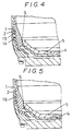
- FIG.4 shows an enlarged sectional view of the third preferred embodiment, with certain parts omitted.
- FIG.5 shows an enlarged sectional view of the fourth preferred embodiment, with certain parts omitted.
- FIG.6 shows an enlarged sectional view of the fifth embodiment, with certain parts omitted.
- FIG.7 shows an enlarged sectional view of the sixth preferred embodiment, with certain parts omitted.
- a cast-iron stationary barrel 1 whose inside and lower part is integrated with polyurethane lining layer 2 is referred to as stationary barrel 3.
- a continuous-porous neoprene rubber plate 7 with a specific thickness (e.g. 6 mm) was circularly arranged between inner wall at lower part of the cast-iron stationary barrel 1 and outer wall of the polyurethane lining layer 2 (Fig. 1).
- This continuous-porous neoprene rubber plate 7 is called as a measure to allow for thermal expansion.
- a cast-iron rotational barrel 4 equipped with polyurethane lining layer 5 at upper part thereof to block bottom part of the stationary barrel 3 is referred to as rotating barrel 6 (Fig. 2).
- Vertical width of the neoprene rubber plate 7 is, for example, 70 mm.
- the size of vertical width of neoprene rubber plate 7 is determined according to the size of vertical width of clearance S between stationary barrel 3 and rotating barrel 6. Anyhow, the sizes of vertical width and thickness of neoprene rubber plate 7 are determined under the condition that the size of clearance S between stationary barrel 3 and rotating barrel 6 is stabilized or kept almost constant at every time, not relating with the thermal expansions of the polyurethane lining layer 2 and the polyurethane lining layer 5.
- the rotating barrel 6 is loosely engaged with lower part inside the stationary barrel 3 so as to rotate freely and oppose to each other forming a fine clearance S (e.g. 0.1 ⁇ 1 mm) (Fig. 2).
- the vertical width of the clearance S between stationary barrel 3 and rotating barrel 6 is, for example, 20 mm.
- the neoprene rubber plate 7 is located at almost same height as the clearance S is positioned.
- an air vent 8 is used for venting the occluded air, which was occluded in the continuous-porous neoprene rubber plate 7, when the continuous-porous neoprene rubber plate 7 is deformed by thermal expansion of the polyurethane lining layer 2.
- numerals 9 and 10 illustrate rotation axis and supporting bottom of the stationary barrel 3, respectively.
- temperatures of the stationary barrel 3 and the rotating barrel 6 increase (e.g. around 60 degree C) as the progress of the finishing process, wherein the polyurethane lining layer 5 of the rotating barrel 6 expands on heating to the arrow direction 11 (outward) resulting in narrowing clearance S; on the other hand, the lining layer 2 of the stationary barrel 3 expands on heating to the arrow direction 12 (toward inner wall of the cast-iron stationary barrel 1), resulting in broadening clearance S.
- the clearance S can be kept constant, even if the barrel finishing machine is used for long time under severe conditions by determining the thicknesses of polyurethane lining layers 2 and 5, and the vertical width and thickness of continuous-porous neoprene rubber plate 7 in order to adjust the effects of thermal expansions of these lining layers 2 and 5 on the clearance S may be compensated by each other.
- Fig. 3 The embodiment of Fig. 3 is carried out by using an air layer 13, in place of the continuous-porous neoprene rubber plate 7 in Example 1, wherein the air layer 13 is, for example, set as 3 ⁇ 4 mm thick and 5 ⁇ 7 cm vertical width. These sizes of thickness and vertical width of air layer may be varied depending upon the condition.
- outer wall of polyurethane lining layer 2 in irregularities such as forming concave parts 15 and convex parts 14 on outer face of the polyurethane lining layer 2 as illustrated in Fig. 4, or by forming circular slits 16 (Fig. 5) or longitudinal slits 17 (Fig. 6).
- the vertical width, and the height or depth of the said irregularities 14, 15, 16, 17 may be chosen to have equivalent absorptive power for thermal expansion of polyurethane lining layer 2 toward the inner wall of stationary barrel 1.
Landscapes
- Engineering & Computer Science (AREA)
- Mechanical Engineering (AREA)
- Finish Polishing, Edge Sharpening, And Grinding By Specific Grinding Devices (AREA)
- Extrusion Moulding Of Plastics Or The Like (AREA)
- Polishing Bodies And Polishing Tools (AREA)
Abstract
Description
- This invention relates to a barrel finishing machine. Particularly, this invention relates to a spiral-flow barrel finishing machine comprising a cylindrical stationary barrel and a rotating barrel which loosely engaged with lower part and inside of said cylindrical stationary barrel so as to rotate freely, with an object to keep a constant clearance between inner wall of the stationary barrel and outer wall of the rotating barrel, not relating with the temperature change and the moisture content change.
- There were some prior arts which disclose a variety of procedures for preventing a clearance between the stationary barrel and the rotating barrel of the spiral-flow barrel finishing machine from changing of its horizontal width, which is caused by thermal expansion. For example. Japanese patent under Provisional Publication No. 5-38670 and Japanese utility model under Provisional Publication No. 3-1130358 disclosed an invention and a device where a stopper is installed inside of lining layer on periphery of a rotating barrel to control deformation of the lining due to thermal expansion. Japanese utility model under Provisional Publication No. 57-53858 disclosed a device where a foreign material is used for a fine clearance at either a stationary barrel part opposed to the fine clearance or a rotating barrel part opposed to the fine clearance. And furthermore, Japanese utility model under Provisional Publication No. 51-62191 disclosed a device where a clearance between a stationary barrel and a rotating barrel is adjusted vertically.
- These prior art procedures produce some negative effects as follows:
- a) The procedure for installing a stopper within the lining layer on periphery of the rotating barrel can not afford to prevent either the clearance from shrinking due to thermal expansion in the severe usage for long time or durable life of the lining from shortening due to exposure of the stopper caused by abrasion of the lining layer. If the stopper is exposed by abrasion of the lining layer, it is necessary to re-install the lining layer. A bimetal type stopper may be available, but an increase in the cost is problematic.
- b) The procedure for using a foreign material at either the stationary barrel part or the rotating barrel part may accelerate abrasion either the materials, resulting in its short durable life.
- c) The procedure for a vertically adjusting a clearance requires an adjusting mechanism, so that it is problematic duc to not only an increase in the cost but also poor sealability.
- While studying direction about thermal expansion of the lining layer, which is installed on the inner wall of the stationary barrel, it has been found that, although the lining layer inside the metallic stationary barrel is to be expanded on heating toward the metallic stationary barrel, it is blocked to expand by the metallic wall of stationary barrel, so that this thermal expansion is forced to divert the direction toward center (inner) of the stationary barrel (resulting in reducing a horizontal width of clearance between inner wall of the lining layer on the stationary barrel and outer wall of the lining layer on the rotating barrel).
- Thereupon, in accordance with this invention, as a measure to allow for thermal expansion of the lining layer installed in lower part inside the stationary barrel, a flexible layer having a specific vertical width, which can be deformed by thermal expansion of the lining layer installed in lower part inside the stationary barrel,is circularly arranged between inner wall of the metallic stationary barrel and outer wall of the lining layer installed in lower part inside the metallic stationary barrel, so that the heretofore mentioned problem has been resolved. In this specification, said flexible layer is called as a measure to allow for thermal expansion.
- Namely, in a spiral-flow barrel finishing machine comprising a cylindrical metallic stationary barrel equipped with lining layer at lower part inside thereof and a rotating barrel equipped with lining layer at upper part of the metallic rotating body, keeping a specific clearance between these lining layers and said rotating barrel is loosely engaged with inside of said metallic stationary barrel so as to block lower part thereof, the spiral-flow barrel finishing machine of this invention is characterized in that a measure to allow for thermal expansion is circularly arranged between inner wall of the metallic stationary barrel and outer wall of the lining layer installed in lower part inside the metallic stationary barrel, having a specific vertical width corresponding to the vertical width of the clearance formed between inner wall of the lining layer on the metallic stationary barrel and outer wall of the lining layer on the rotating barrel.
- In the above description, a measure to allow for thermal expansion may be made up by installing an easily deformable elastic layer or air layer, used by alone or combined, between inner wall of the metallic stationary barrel and outer wall of the lining layer installed in lower part inside the metallic stationary barrel.
- Furthermore, it may be altered, a cylindrical metallic stationary barrel may be comprised by a cast-iron body and a polyurethane lining layer installed in lower part inside the said cast-iron body, and a measure to allow for thermal expansion may be made up by installing a continuous-porous material layer between inner wall of the said cast-iron stationary barrel and outer wall of the said polyurethane lining layer. Moreover, a measure to allow for thermal expansion may be made up by molding irregularities on outer wall of the lining layer facing to inner wall of the said cast-iron stationary body.
- As described above, by circularly arranging a measure to allow for thermal expansion of the lining layer installed in lower part inside the metallic stationary barrel between inner wall of the metallic stationary barrel and outer wall of the lining layer installed in lower part inside the said metallic stationary barrel, the said lining layer may be feasible to expand freely on heating toward the wall side of the said metallic stationary barrel. Accordingly, the clearance between the stationary barrel and the rotating barrel of the spiral-flow barrel finishing machine can always be kept constant, not relating with the temperature change and the moisture content change.
- In the above description, the vertical width of the said measure to allow for thermal expansion may be required to have a specific correlation with the vertical width of the clearance between inner wall of the lining layer installed in lower part inside the metallic stationary barrel and outer wall of the lining layer installed on rotating barrel, because at least by choosing the same size for both vertical widths, preferably larger size for the former, the said clearance can be adjusted to keep constant at every position across the vertical width of the said clearance.
- Namely, the before described measure to allow for thermal expansion of the lining layer installed in lower part inside the metallic stationary barrel is circularly arranged, and its vertical width is preferable to be about 3-fold larger than the vertical width of the clearance to be adjusted. The reason of why is that adjustment of the clearance can be carried out more correctly and easily comparing with the case when the width is not large enough as 3-fold size. Also, even if the vertical width is chosen to be much larger than the 3-fold size, neither specific effects of adjustment of the clearance nor profits in manufacturing and cost are expected. Practically, vertical width of the measure to allow for thermal expansion is determined for preventing the size of clearance between the stationary barrel and the rotating barrel from being affected by the thermal expansion of the lining layer installed in lower part inside the metallic stationary barrel.
- Furthermore, in the above description, it is preferable to locate the measure to allow for thermal expansion of the lining layer installed in lower part inside the metallic stationary barrel at almost the same height as the clearance between these barrels is positioned. By taking such as almost same height, it is feasible to effectively adjust the clearance while keeping the clearance uniformly across the every vertical direction.
- Moreover, in the above description, thickness of the measure to allow for thermal expansion such as thicknesses of the elastic layer, air layer and continuous-porous material layer, or height or depth of irregularities in lining layer facing to inner wall of the metallic stationary barrel, are chosen to have equivalent absorptive power for thermal expansion of the lining layer installed in lower part inside the metallic stationary barrel, orientating to inner wall thereof.
- For example, assuming that 0.5∼1.5 mm of thermal expansion of the lining layer installed in lower part inside the metallic stationary barrel takes place at 60∼70 degree C temperature of the stationary barrel or the rotating barrel, at least 6 mm thickness of the measure to allow for thermal expansion is required. But, in case of the air layer, the 4 mm-thick layer may be enough to attain the purpose.
- Then, since the lining layer on the rotating barrel expands on heating outwardly (toward narrowing the clearance between inner wall of the lining layer installed in lower part inside the metallic stationary barrel and outer wall of the lining layer on the rotating barrel) and the lining layer on the stationary barrel also expands on heating outwardly (toward widening the said clearance), the clearance between the stationary barrel and the rotating barrel remains constant (that is to say, it remains design size) in the case when no different amounts of the thermal expansion exist between these lining layers. Accordingly, in order to keep a constant clearance between the stationary barrel and the rotating barrel, it is desirable that the external thermal expansion of the lining layer on the rotating barrel (toward narrowing the clearance) and the external thermal expansion of the lining layer on the stationary barrel (toward widening the clearance) are kept at relatively the same rate at each temperature range.
- In the above description, if the lining layer on the stationary barrel is thick and the lining layer on the rotating barrel is thin, as the temperature increases, amount of thermal expansion of the former lining layer becomes so large that some adjustment may be carried out to let a part of the former lining layer capable to expand inwardly by increasing deformation resistance of the measure to allow for thermal expansion (e.g. by using continuous-porous material layer). Thereupon, by choosing the measure to allow for thermal expansion (e.g. continuous-porous material layer) with required thickness, such as with 4 mm thickness, instead of usual 6 mm thickness, a method to preferably adjust the thermal expansion may be achieved; i.e. outward expansion of the lining layer on the stationary barrel is proceeded smoothly at the initial stage, and then two-way expansions such as outward and inward expansions of the lining layer on the stationary barrel are caused along with the increase of the amount of thermal expansion as the temperature increases according to the deformation resistance of the measure to allow for thermal expansion having a specific thickness such as with 4 mm thickness. In this method, the purpose may be achieved by adjusting not only thickness but also vertical width of the measure to allow for thermal expansion (e.g. continuous-porous material layer).
- Further, another spiral-flow barrel finishing machine of this invention comprises a cylindrical stationary barrel and a rotating barrel equipped with lining layer at upper part of the metallic rotational body wherein a specific clearance is kept between inner wall at lower part of said cylindrical stationary barrel and outer wall of the lining layer on said rotating barrel which loosely engaged with inside of said cylindrical stationary barrel so as to block lower part thereof, characterized in that the cylindrical stationary barrel is made of the same material as that of the lining layer on the rotating barrel.
- In this case, for example, provided that lining layer of the rotating barrel is made of polyurethane, the cylindrical stationary barrel may be made by polyurethane. By doing so, when the rotating barrel expands outward on heating, the stationary barrel expands outward at the same rate, so that the clearance between these barrels remains constant not relating with the temperature change and the moisture content change. Also, in this case, it is not necessary to install a special measure to allow for thermal expansion, such as elastic layer, air layer or continuous-porous material layer, or irregularities of lining layer facing inner wall of the metallic stationary barrel, between inner wall of the metallic stationary barrel and outer wall of the lining layer installed in lower part inside the metallic stationary barrel as the before described cases.
- In accordance with this invention, since the clearance between stationary barrel and rotating barrel is always kept constant, as explained above, even if the clearance is determined as fine as allowable at the beginning of the design, any worrisome problem such as closing and meltdown of the clearance may be prevented. It gives another profitable outcome of being able to polish or finish materials in the barrel using fine workpieces, thin plate workpieces, fine abrasive chips without taking account of their blocking or fastening on the clearance between the stationary barrel and the rotating barrel.
- In the case when continuous-porous material is used as a measure to allow for thermal expansion of the polyurethane lining, the said continuous-porous material having a specific vertical width and specific thickness is fixed on a definite part of inner wall of the metallic stationary barrel at the first, and then the lining layer may be equipped inside the metallic stationary barrel by the same molding procedure, which has been adopted in manufacturing conventional spiral-flow barrel finishing machine, without causing any further cost other than the cost required for manufacturing conventional spiral-flow barrel finishing machine.
- The rotating barrel of spiral-flow barrel finishing machine of this invention has advantageous effect so that installation of a stopper in the lining layer of rotating barrel for controlling thermal expansion of the said lining layer, as described in prior art, and thinning of a lining layer on the stationary barrel are not necessary. Hitherto, since thick lining layer of the stationary barrel yields large amount of inward expansion on heating, the upper thickness of lining layer on the stationary barrel has been limited.
- According to the present invention, the thickness of lining layer on the stationary barrel may be increased comparing to that of conventional spiral-flow barrel finishing machine, the spiral-flow barrel finishing machine of the present invention may be used for a long time, since it takes long time till the lining layer on the stationary barrel is worn off. Therefore, the life span of spiral-flow barrel finishing machine may be increased, and it may provide a cost merit comparing to the structure of prior art in which the stopper is installed in the lining layer of rotating barrel.
- FIG.1 shows a front view, partially in cross section, of a preferred embodiment of this invention.
- FIG.2 shows an enlarged sectional view of the preferred embodiment illustrated in FIG. 1, with certain parts omitted.
- FIG.3 shows an enlarged sectional view of the second preferred embodiment, with certain parts omitted.
- FIG.4 shows an enlarged sectional view of the third preferred embodiment, with certain parts omitted.
- FIG.5 shows an enlarged sectional view of the fourth preferred embodiment, with certain parts omitted.
- FIG.6 shows an enlarged sectional view of the fifth embodiment, with certain parts omitted.
- FIG.7 shows an enlarged sectional view of the sixth preferred embodiment, with certain parts omitted.
- A preferable embodiment of this invention will be described hereinafter by using accompanying drawings.
- As shown in Fig. 1 and Fig. 2, a cast-iron
stationary barrel 1 whose inside and lower part is integrated withpolyurethane lining layer 2 is referred to asstationary barrel 3. In thisstationary barrel 3, a continuous-porous neoprene rubber plate 7 with a specific thickness (e.g. 6 mm) was circularly arranged between inner wall at lower part of the cast-ironstationary barrel 1 and outer wall of the polyurethane lining layer 2 (Fig. 1). This continuous-porous neoprene rubber plate 7 is called as a measure to allow for thermal expansion. Meanwhile, a cast-ironrotational barrel 4 equipped withpolyurethane lining layer 5 at upper part thereof to block bottom part of thestationary barrel 3 is referred to as rotating barrel 6 (Fig. 2). - Vertical width of the neoprene rubber plate 7 is, for example, 70 mm. The size of vertical width of neoprene rubber plate 7 is determined according to the size of vertical width of clearance S between
stationary barrel 3 androtating barrel 6. Anyhow, the sizes of vertical width and thickness of neoprene rubber plate 7 are determined under the condition that the size of clearance S betweenstationary barrel 3 androtating barrel 6 is stabilized or kept almost constant at every time, not relating with the thermal expansions of thepolyurethane lining layer 2 and thepolyurethane lining layer 5. - The
rotating barrel 6 is loosely engaged with lower part inside thestationary barrel 3 so as to rotate freely and oppose to each other forming a fine clearance S (e.g. 0.1∼1 mm) (Fig. 2). In this embodiment, the vertical width of the clearance S betweenstationary barrel 3 androtating barrel 6 is, for example, 20 mm. As shown in Fig. 1 and Fig. 2, the neoprene rubber plate 7 is located at almost same height as the clearance S is positioned. - In Figure 2, an
air vent 8 is used for venting the occluded air, which was occluded in the continuous-porous neoprene rubber plate 7, when the continuous-porous neoprene rubber plate 7 is deformed by thermal expansion of thepolyurethane lining layer 2. Also, in Fig. 2,numerals stationary barrel 3, respectively. - In this embodiment, while the
barrel 6 filled with workpieces and abrasive chips is rotating, temperatures of thestationary barrel 3 and therotating barrel 6 increase (e.g. around 60 degree C) as the progress of the finishing process, wherein thepolyurethane lining layer 5 of therotating barrel 6 expands on heating to the arrow direction 11 (outward) resulting in narrowing clearance S; on the other hand, thelining layer 2 of thestationary barrel 3 expands on heating to the arrow direction 12 (toward inner wall of the cast-iron stationary barrel 1), resulting in broadening clearance S. - In this case, if the effects of thermal expansion of these
lining layers polyurethane lining layer 5 is smaller than that of thepolyurethane lining layer 2, the clearance S becomes wider. - Therefore, the clearance S can be kept constant, even if the barrel finishing machine is used for long time under severe conditions by determining the thicknesses of
polyurethane lining layers lining layers - The embodiment of Fig. 3 is carried out by using an
air layer 13, in place of the continuous-porous neoprene rubber plate 7 in Example 1, wherein theair layer 13 is, for example, set as 3∼4 mm thick and 5∼7 cm vertical width. These sizes of thickness and vertical width of air layer may be varied depending upon the condition. - Also, the same effect is expected by forming outer wall of
polyurethane lining layer 2 in irregularities such as formingconcave parts 15 and convex parts 14 on outer face of thepolyurethane lining layer 2 as illustrated in Fig. 4, or by forming circular slits 16 (Fig. 5) or longitudinal slits 17 (Fig. 6). - The vertical width, and the height or depth of the said
irregularities polyurethane lining layer 2 toward the inner wall ofstationary barrel 1. - Furthermore, provided that a continuous-porous neoprene rubber plate 18 and an
air layer 19 are arranged in combination as shown in Fig. 7, the same effect is expected. - Although the present invention has been described with reference to the particular preferred embodiments, it should be understood that various changes and modifications may be made within the spirit and scope of the invention as defined in the appended claims.
Claims (5)
- A spiral-flow barrel finishing machine comprising a metallic cylindrical stationary barrel equipped with lining layer at lower part inside thereof and a rotating barrel which is equipped with lining layer at upper part of a metallic rotational body, keeping a specific clearance between inner wall of the lining layer on said metallic stationary barrel and outer wall of the lining layer on said rotating barrel wherein said rotating barrel is loosely engaged with inside of said metallic stationary barrel so as to block lower part thereof, characterized in that a measure to allow for thermal expansion having a definite vertical width, corresponding to the vertical width of the clearance between inner wall of the lining layer on the metallic stationary barrel and outer wall of the lining layer on the rotating barrel, is circularly arranged between inner wall of the metallic stationary barrel and outer wall of the lining layer on the said metallic stationary barrel.
- The spiral-flow barrel finishing machine described in claim 1, characterized in that, a measure to allow for thermal expansion comprises elastic layer or air layer, used by alone or in combination, which is easily deformed due to thermal expansion of lining layer on the metallic stationary barrel and installed between inner wall of the metallic stationary barrel and outer wall of the lining layer on the metallic stationary barrel.
- The spiral-flow barrel finishing machine described in claim 1, characterized in that a metallic cylindrical stationary barrel comprises a cast-iron stationary barrel and a polyurethane lining layer installed in lower part inside the said cast-iron stationary barrel, and a measure to allow for thermal expansion comprises continuous-porous material layer, which is arranged between inner wall of said cast-iron stationary barrel and outer wall of said polyurethane lining layer.
- The spiral-flow barrel finishing machine described in claim 1, characterized in that a measure to allow for thermal expansion comprises irregularities, which are formed on outer wall of the lining layer on the metallic stationary barrel and facing inner wall of the said metallic stationary barrel.
- A spiral-flow barrel finishing machine comprising a cylindrical stationary barrel and a rotating barrel which is equipped with lining layer at upper part of a metallic rotational body, keeping a specific clearance between inner wall at lower side of said cylindrical stationary barrel and outer wall of the lining layer on said rotating barrel wherein said rotating barrel is loosely engaged with inside of said cylindrical stationary barrel so as to block lower part thereof, characterized in that the cylindrical stationary barrel is made of the same material as that of the lining layer of the said rotating barrel.
Applications Claiming Priority (3)
| Application Number | Priority Date | Filing Date | Title |
|---|---|---|---|
| JP3842896 | 1996-02-26 | ||
| JP8038428A JP3062800B2 (en) | 1996-02-26 | 1996-02-26 | Eddy barrel processing machine |
| JP38428/96 | 1996-02-26 |
Publications (2)
| Publication Number | Publication Date |
|---|---|
| EP0791430A1 true EP0791430A1 (en) | 1997-08-27 |
| EP0791430B1 EP0791430B1 (en) | 2000-10-11 |
Family
ID=12525049
Family Applications (1)
| Application Number | Title | Priority Date | Filing Date |
|---|---|---|---|
| EP97301250A Expired - Lifetime EP0791430B1 (en) | 1996-02-26 | 1997-02-26 | Spiral-flow barrel finishing machine |
Country Status (4)
| Country | Link |
|---|---|
| US (1) | US5823861A (en) |
| EP (1) | EP0791430B1 (en) |
| JP (1) | JP3062800B2 (en) |
| DE (1) | DE69703257T2 (en) |
Cited By (7)
| Publication number | Priority date | Publication date | Assignee | Title |
|---|---|---|---|---|
| FR2783450A1 (en) * | 1998-09-22 | 2000-03-24 | Helmut Gegenheimer | POLISHING MACHINE WITH CENTRIFUGAL FORCE AND INTERVAL ADJUSTMENT |
| WO2000056501A1 (en) * | 1999-03-19 | 2000-09-28 | Gegenheimer, Helmut | Grinding machine |
| US6733374B2 (en) | 2000-02-29 | 2004-05-11 | Otec Prazisionsfinish Gmbh | Grinding machine |
| DE202009004268U1 (en) | 2009-03-31 | 2010-05-27 | Otec Präzisionsfinish GmbH | Centrifugal vibratory finishing machine with a device for adjusting the gap width |
| EP2239096A1 (en) | 2009-03-25 | 2010-10-13 | Otec Präzisionsfinish GmbH | Centrifugal force grinding machine with a device for setting the gap width |
| DE202013002000U1 (en) | 2013-03-04 | 2014-03-13 | Otec Präzisionsfinish GmbH | Centrifugal sliding grinder |
| WO2016169101A1 (en) * | 2015-04-23 | 2016-10-27 | 浙江湖磨抛光磨具制造有限公司 | Seamless flowing-type finishing machine |
Families Citing this family (11)
| Publication number | Priority date | Publication date | Assignee | Title |
|---|---|---|---|---|
| JP2913473B2 (en) * | 1997-01-31 | 1999-06-28 | 株式会社チップトン | Eddy current barrel processing machine having gap adjusting function, method for forming escape layer, and gap adjusting method |
| DE29702859U1 (en) * | 1997-02-19 | 1998-03-19 | Gegenheimer, Helmut, 75210 Keltern | Centrifugal vibratory grinding machine |
| IT238331Y1 (en) * | 1997-05-30 | 2000-10-16 | Hyppocampus Srl | MACHINE FOR DRYING, POLISHING AND REGENERATION TREATMENTS DISPOSED AND METAL OBJECTS FROM THE TABLE |
| DE20018805U1 (en) * | 2000-11-03 | 2001-01-04 | OTEC Präzisionsfinish GmbH, 75334 Straubenhardt | Grinding machine |
| JP4453624B2 (en) * | 2005-07-21 | 2010-04-21 | 株式会社ジェイテクト | Cam follower |
| JP5266890B2 (en) * | 2008-06-04 | 2013-08-21 | 新東工業株式会社 | Fluid barrel polishing equipment |
| JP5838044B2 (en) * | 2011-05-31 | 2015-12-24 | 日立オートモティブシステムズ株式会社 | Deburring apparatus and cylinder manufacturing method using the same |
| DE102013204816A1 (en) | 2013-03-19 | 2014-09-25 | Rösler Holding GmbH & Co. KG | SLIDING MACHINE AND PROCESSING FOR COLUMN ADJUSTMENT |
| US12337437B2 (en) | 2019-03-29 | 2025-06-24 | Sintokogio, Ltd. | Barrel polishing device |
| CN111716233A (en) * | 2020-07-24 | 2020-09-29 | 方国权 | A low-noise high-speed centrifugal grinding and polishing machine |
| CN113787447B (en) * | 2021-09-26 | 2022-07-08 | 徐州万泽机械科技有限公司 | Double-sided polishing device for differential shell |
Citations (5)
| Publication number | Priority date | Publication date | Assignee | Title |
|---|---|---|---|---|
| DE2705445A1 (en) * | 1976-02-09 | 1977-08-11 | Osro Ltd | MACHINE FOR SURFACE TREATMENT, SUCH AS GRINDING OR POLISHING, OF WORKPIECES |
| DE3332787A1 (en) * | 1983-09-10 | 1985-03-28 | Carl Kurt Walther Gmbh & Co Kg, 5600 Wuppertal | Container for barrel finishing |
| JPH0538670A (en) * | 1991-07-29 | 1993-02-19 | Tipton Mfg Corp | Vortex flow barrel processing machine |
| JPH06278010A (en) * | 1993-01-29 | 1994-10-04 | Riuge Seiki Kk | Dry type vertical barrel polishing machine |
| DE4324132A1 (en) * | 1993-07-19 | 1995-01-26 | Roesler Roland Oberflaechen | Method for measuring the gap width in centrifugal-force tumbling machines and associated apparatus |
Family Cites Families (5)
| Publication number | Priority date | Publication date | Assignee | Title |
|---|---|---|---|---|
| DE3604619A1 (en) * | 1986-02-14 | 1987-08-20 | Spaleck Gmbh Max | CENTRIFUGAL MACHINE |
| US4884372A (en) * | 1987-10-06 | 1989-12-05 | Roto-Finish Company, Inc. | Centrifugal finishing apparatus embodying improved seal and method |
| US5012620A (en) * | 1987-10-06 | 1991-05-07 | Roto-Finish Company, Inc. | Centrifugal finishing apparatus embodying improved seal and method |
| DE3812908A1 (en) * | 1988-04-18 | 1989-10-26 | Walther Carl Kurt Gmbh | CENTRIFUGAL GRINDING MACHINE |
| JPH075974Y2 (en) * | 1990-04-06 | 1995-02-15 | 株式会社チップトン | Swirl barrel machine |
-
1996
- 1996-02-26 JP JP8038428A patent/JP3062800B2/en not_active Expired - Lifetime
-
1997
- 1997-02-26 US US08/806,623 patent/US5823861A/en not_active Expired - Lifetime
- 1997-02-26 DE DE69703257T patent/DE69703257T2/en not_active Expired - Lifetime
- 1997-02-26 EP EP97301250A patent/EP0791430B1/en not_active Expired - Lifetime
Patent Citations (5)
| Publication number | Priority date | Publication date | Assignee | Title |
|---|---|---|---|---|
| DE2705445A1 (en) * | 1976-02-09 | 1977-08-11 | Osro Ltd | MACHINE FOR SURFACE TREATMENT, SUCH AS GRINDING OR POLISHING, OF WORKPIECES |
| DE3332787A1 (en) * | 1983-09-10 | 1985-03-28 | Carl Kurt Walther Gmbh & Co Kg, 5600 Wuppertal | Container for barrel finishing |
| JPH0538670A (en) * | 1991-07-29 | 1993-02-19 | Tipton Mfg Corp | Vortex flow barrel processing machine |
| JPH06278010A (en) * | 1993-01-29 | 1994-10-04 | Riuge Seiki Kk | Dry type vertical barrel polishing machine |
| DE4324132A1 (en) * | 1993-07-19 | 1995-01-26 | Roesler Roland Oberflaechen | Method for measuring the gap width in centrifugal-force tumbling machines and associated apparatus |
Non-Patent Citations (2)
| Title |
|---|
| PATENT ABSTRACTS OF JAPAN vol. 17, no. 324 (M - 1433) 21 June 1993 (1993-06-21) * |
| PATENT ABSTRACTS OF JAPAN vol. 95, no. 1 28 February 1995 (1995-02-28) * |
Cited By (9)
| Publication number | Priority date | Publication date | Assignee | Title |
|---|---|---|---|---|
| FR2783450A1 (en) * | 1998-09-22 | 2000-03-24 | Helmut Gegenheimer | POLISHING MACHINE WITH CENTRIFUGAL FORCE AND INTERVAL ADJUSTMENT |
| US6213854B1 (en) | 1998-09-22 | 2001-04-10 | Helmut Gegenheimer | Centrifugal force sliding grinding machine with gap adjustment |
| DE19843366B4 (en) * | 1998-09-22 | 2005-07-21 | Helmut Gegenheimer | Centrifugal vibratory finishing machine with gap adjustment |
| WO2000056501A1 (en) * | 1999-03-19 | 2000-09-28 | Gegenheimer, Helmut | Grinding machine |
| US6733374B2 (en) | 2000-02-29 | 2004-05-11 | Otec Prazisionsfinish Gmbh | Grinding machine |
| EP2239096A1 (en) | 2009-03-25 | 2010-10-13 | Otec Präzisionsfinish GmbH | Centrifugal force grinding machine with a device for setting the gap width |
| DE202009004268U1 (en) | 2009-03-31 | 2010-05-27 | Otec Präzisionsfinish GmbH | Centrifugal vibratory finishing machine with a device for adjusting the gap width |
| DE202013002000U1 (en) | 2013-03-04 | 2014-03-13 | Otec Präzisionsfinish GmbH | Centrifugal sliding grinder |
| WO2016169101A1 (en) * | 2015-04-23 | 2016-10-27 | 浙江湖磨抛光磨具制造有限公司 | Seamless flowing-type finishing machine |
Also Published As
| Publication number | Publication date |
|---|---|
| JP3062800B2 (en) | 2000-07-12 |
| US5823861A (en) | 1998-10-20 |
| DE69703257D1 (en) | 2000-11-16 |
| EP0791430B1 (en) | 2000-10-11 |
| JPH09225808A (en) | 1997-09-02 |
| DE69703257T2 (en) | 2001-03-15 |
Similar Documents
| Publication | Publication Date | Title |
|---|---|---|
| US5823861A (en) | Spiral-flow barrel finishing machine | |
| US6110025A (en) | Containment ring for substrate carrier apparatus | |
| US5437757A (en) | Clamp ring for domed pedestal in wafer processing chamber | |
| CA1179396A (en) | Device for mounting a support and articulation arm of a sun-glare shield of a vehicle | |
| US7311871B2 (en) | Process for foaming around the peripheral edge area of cover for a motor vehicle roof and a motor vehicle roof cover | |
| WO2005049274A2 (en) | Retaining ring with shaped surface | |
| US6394658B1 (en) | Bearing systems having reduced noise and axial preload | |
| JP2001127025A (en) | Chemical mechanical polishing equipment | |
| US7101272B2 (en) | Carrier head for thermal drift compensation | |
| US6517150B2 (en) | Plastic cover for motor vehicles | |
| GB2337712A (en) | Processing a peripheral portion of a thin plate | |
| HU181603B (en) | Lock plate unit for gate valve | |
| US5591264A (en) | Spin coating device | |
| JP3164045B2 (en) | Semiconductor wafer mounting base | |
| US5591245A (en) | Method and apparatus for developing and edge stress in a windshield in a windshield bending furnace | |
| US6641461B2 (en) | Chemical mechanical polishing apparatus having edge, center and annular zone control of material removal | |
| US6706140B2 (en) | Control system for in-situ feeding back a polish profile | |
| KR100347026B1 (en) | Height adjusting apparatus for refrigerator and door the same | |
| US5318097A (en) | Cassette for forming an end closing side of a device for continuously coating liquid metal | |
| JPH0752034A (en) | Wafer polishing machine | |
| JPH06333810A (en) | Heat treatment equipment | |
| WO2002016080A2 (en) | Substrate supporting carrier pad | |
| KR100321551B1 (en) | Improved semiconductor wafer polishing device for removing a surface unevenness of a semiconductor substrate | |
| KR200272218Y1 (en) | Valve structure for sealing at the top of blast furnace | |
| KR200172767Y1 (en) | Device for regulating the press-pad position of a side trimmer |
Legal Events
| Date | Code | Title | Description |
|---|---|---|---|
| PUAI | Public reference made under article 153(3) epc to a published international application that has entered the european phase |
Free format text: ORIGINAL CODE: 0009012 |
|
| AK | Designated contracting states |
Kind code of ref document: A1 Designated state(s): DE |
|
| 17P | Request for examination filed |
Effective date: 19971104 |
|
| 17Q | First examination report despatched |
Effective date: 19990325 |
|
| GRAG | Despatch of communication of intention to grant |
Free format text: ORIGINAL CODE: EPIDOS AGRA |
|
| 17Q | First examination report despatched |
Effective date: 19990325 |
|
| GRAG | Despatch of communication of intention to grant |
Free format text: ORIGINAL CODE: EPIDOS AGRA |
|
| GRAH | Despatch of communication of intention to grant a patent |
Free format text: ORIGINAL CODE: EPIDOS IGRA |
|
| GRAH | Despatch of communication of intention to grant a patent |
Free format text: ORIGINAL CODE: EPIDOS IGRA |
|
| GRAA | (expected) grant |
Free format text: ORIGINAL CODE: 0009210 |
|
| AK | Designated contracting states |
Kind code of ref document: B1 Designated state(s): DE |
|
| REF | Corresponds to: |
Ref document number: 69703257 Country of ref document: DE Date of ref document: 20001116 |
|
| EN | Fr: translation not filed | ||
| PLBE | No opposition filed within time limit |
Free format text: ORIGINAL CODE: 0009261 |
|
| STAA | Information on the status of an ep patent application or granted ep patent |
Free format text: STATUS: NO OPPOSITION FILED WITHIN TIME LIMIT |
|
| 26N | No opposition filed | ||
| PGFP | Annual fee paid to national office [announced via postgrant information from national office to epo] |
Ref country code: DE Payment date: 20160302 Year of fee payment: 20 |
|
| REG | Reference to a national code |
Ref country code: DE Ref legal event code: R071 Ref document number: 69703257 Country of ref document: DE |