EP0794381B1 - Wasserschadenschutzvorrichtung - Google Patents
Wasserschadenschutzvorrichtung Download PDFInfo
- Publication number
- EP0794381B1 EP0794381B1 EP96111015A EP96111015A EP0794381B1 EP 0794381 B1 EP0794381 B1 EP 0794381B1 EP 96111015 A EP96111015 A EP 96111015A EP 96111015 A EP96111015 A EP 96111015A EP 0794381 B1 EP0794381 B1 EP 0794381B1
- Authority
- EP
- European Patent Office
- Prior art keywords
- sensor
- closing means
- water
- volume flow
- electronic control
- Prior art date
- Legal status (The legal status is an assumption and is not a legal conclusion. Google has not performed a legal analysis and makes no representation as to the accuracy of the status listed.)
- Expired - Lifetime
Links
- XLYOFNOQVPJJNP-UHFFFAOYSA-N water Substances O XLYOFNOQVPJJNP-UHFFFAOYSA-N 0.000 title claims description 67
- 238000000034 method Methods 0.000 claims description 8
- 238000012544 monitoring process Methods 0.000 claims description 7
- 239000007788 liquid Substances 0.000 claims description 5
- 230000000694 effects Effects 0.000 claims description 3
- 238000010079 rubber tapping Methods 0.000 claims description 3
- 238000012360 testing method Methods 0.000 claims description 3
- 230000036962 time dependent Effects 0.000 claims description 3
- 238000004891 communication Methods 0.000 claims description 2
- 208000033748 Device issues Diseases 0.000 claims 1
- 238000009434 installation Methods 0.000 abstract description 7
- 238000011161 development Methods 0.000 description 5
- 230000018109 developmental process Effects 0.000 description 5
- 238000005259 measurement Methods 0.000 description 3
- 238000004140 cleaning Methods 0.000 description 2
- 230000005611 electricity Effects 0.000 description 2
- 239000003792 electrolyte Substances 0.000 description 2
- 230000003247 decreasing effect Effects 0.000 description 1
- 238000001514 detection method Methods 0.000 description 1
- 238000010586 diagram Methods 0.000 description 1
- 239000003651 drinking water Substances 0.000 description 1
- 235000020188 drinking water Nutrition 0.000 description 1
- 239000012530 fluid Substances 0.000 description 1
- 230000003287 optical effect Effects 0.000 description 1
- 210000000056 organ Anatomy 0.000 description 1
- 230000001681 protective effect Effects 0.000 description 1
- 230000008054 signal transmission Effects 0.000 description 1
- 238000005406 washing Methods 0.000 description 1
- 238000009736 wetting Methods 0.000 description 1
Images


Classifications
-
- F—MECHANICAL ENGINEERING; LIGHTING; HEATING; WEAPONS; BLASTING
- F17—STORING OR DISTRIBUTING GASES OR LIQUIDS
- F17D—PIPE-LINE SYSTEMS; PIPE-LINES
- F17D5/00—Protection or supervision of installations
- F17D5/02—Preventing, monitoring, or locating loss
Definitions
- the invention relates to a device with a closure member for automatic closing of a hose or Pipeline for the transport of liquid media, in particular Water, when a signal occurs, e.g. B. when exceeded a predeterminable, monitored by a sensor Limit value from this sensor or one downstream of the sensor Electronics is generated, with at least two Moisture sensors in the floor area of a protected area Space or a building with several taps arranged are, and that the closure member is in the central Supply line to the tap is located.
- a signal e.g. B. when exceeded a predeterminable, monitored by a sensor Limit value from this sensor or one downstream of the sensor Electronics is generated, with at least two Moisture sensors in the floor area of a protected area Space or a building with several taps arranged are, and that the closure member is in the central Supply line to the tap is located.
- Such a device is known from GB-A 2202358.
- Appropriate water damage protection devices for. separate devices connected to a water supply network are e.g. B. known from US-PS 5 086 806 and EP 0.222 174.
- EP 0 257 575 Another similar device is known from EP 0 257 575, but for the protection of entire piping systems is determined and thus complex monitoring lines along the entire main and branch lines.
- the object of the present invention is a Device and a method of the type described in the introduction to imagine that in the event of damage, the water supply reliably shuts off, the emerging water volume and the restriction of comfort should be minimized.
- This object is achieved in that in the central supply line additionally in front of or behind the closure member a volume flow meter in the hose or pipeline is arranged, the electrical measurement signals in Dependence on the volume flow through the hose or pipe as well as the flow time, and that a Electronic control device is provided, the measurement signals are supplied, and which are based on a specifiable, stored programs depending on the received Measurement signals, for example when a Limit value, control signals either directly to the closure member or delivers to an actuator that cause a closing or opening of the closure member.
- the electrical contact between the moisture sensor is preferred and plug-in housing, which is the assembly simplified.
- a particularly comfortable embodiment of the invention can use one or more of the sensors used Radio connected to the electronic control device his. This eliminates the need for a low voltage network for signal transmission in the building.
- one or several of the sensors used on the electrical Electricity network of the building in question with the electronic Control device to be connected. This also makes one Radio system saved as in the previous embodiment.
- the sensors have a standardized electrical Socket connection on, with which they simply in one in the socket in the room in question can.
- the moisture sensor and / or the wall housing with a reset switch to reopen of the closure member is equipped. This can the closure member after closing the central feed line from the installation location of the sensor (or the housing) can be opened again by manually operating the switch.
- a central one Sensor for monitoring the time-dependent volume flow provided in the supply line in addition to the humidity sensors, a central one Sensor for monitoring the time-dependent volume flow provided in the supply line. So the number the required humidity sensors for monitoring for example, kept an entire house relatively small become.
- volume flow sensor interacts with the electronic control device closing the Closure member causes when a specified as a limit Volume flow is exceeded if the duration of an uninterrupted Water withdrawal a predetermined limit exceeds or if the water volume tapped without interruption exceeds a predefinable limit.
- Adjustment devices are provided with which the limit values are preset so that the system according to the respective Operator needs can be set.
- Moisture sensors used when wetted with water change their electrical conductivity. In this way can be directly affected by the effects of moisture electrical control signals are generated.
- the Moisture sensors each have two electrodes, between which electrical current can only flow, if there is water as an electrolyte between them. In order to prevents the corresponding moisture sensor responds to a liquid other than water.
- Moisture sensors contain a body that its volume changes when it comes into contact with water, an electrical switch via this change in volume is operated.
- the humidity sensors used have a float switch included at a developing fluid level floats up and actuates an electrical switch.
- a method of operation also falls within the scope of the invention a device of the type described above, in which the central locking device is closed automatically, if any of the installed moisture sensors are damp finds. This will cause a leak in the water network, for example a broken pipe further flow of water prevented, so that the scope the resulting water damage can be limited considerably can.
- central locking member controlled on the one hand by the moisture sensors, but also closed when a central volume flow meter detects a limit violation. This can also cause water to escape, for example to the outside in the event of a water pipe break in an outer wall of the building be stopped without moisture sensors outside must be present.
- this method variant is particularly preferred, where that by exceeding the limit closed shutter after a certain shutter time is automatically reopened and kept open if the volume flow is smaller after opening than before closing or decreased to 0 l / h, however is closed again immediately if this is not the case Is the case, this test at least at intervals is repeated once, preferably several times.
- This has the user the option of using his water damage protection device to communicate. For example, he should tapped water for too long or a maximum permissible volume flow have exceeded, the water damage protection device closes first the supply line, however, can after a short time, once she registered that no If there is a real damage, release the water network again.
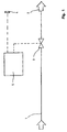
- a preferred variant has in the central water inlet (1) e.g. B. behind the water meter of the public water supplier and a central one in front of the water distributor (2) Closure member (3) (Fig. 1) z. B. a diaphragm valve, which is controlled with a solenoid valve.
- Closure member (3) Fig. 1
- z. B. a diaphragm valve, which is controlled with a solenoid valve.
- a broken water pipe or other leaks of the water network to be protected (Fig. 2) are in the most critical areas (tapping points, Washing machine, dishwasher etc.) humidity sensors (4) attached, the moisture occurring in the floor area (11) can recognize and in collaboration with a electronic control device (5) when occurrence of Moisture cause the central occlusion organ (3) the water supply stops.
- the sensors (4) (Fig. 3) are with the electronic control device (5) via electrical Low voltage lines (6, 6a) connected.
- the sensors (4) are particularly preferred (FIG. 3) a firm z. B. in the wall (12) installable housing (7) connected to the extra-low voltage network (6). Most notably the electrical contact between the (sensor) line is preferred (6a) and the housing (7) with the help of a light separable connector.
- the sensors (4) and the connection housing (7) are whole particularly preferably equipped with a reset switch (8), to after closing the closure member (3) to be able to open it again from where the sensor is installed.
- a preferred moisture sensor (4) works on the basis an electrical conductivity change due to wetting the sensor with water.
- the moisture sensor (4) particularly preferably contains one Arrangement of two electrodes, between which only electrical Electricity can flow if (in the event of damage) between them is water as an electrolyte.
- Another preferred type of moisture sensor includes one Body that changes volume when mixed with water comes into contact and an electrical one via this volume change Switch operated.
- Another preferred type of moisture sensor includes one Float switch, which is at a developing liquid level floats up and so an electrical switch actuated.
- a water damage protection device according to Examples 1- 3 is operated particularly advantageously as follows:
- the moisture sensor (4) from the housing (7), for. B. means a connector to be disconnected to a disability to avoid floor cleaning work by the sensor and also a signal trigger by cleaning water to prevent.
- a system is particularly advantageous tolerated some time (e.g. a few minutes) during the the sensor is unplugged, but in the event that the sensor was forgotten, the operator by closing it of the closure member (3) forces or at least by means of an optical or acoustic signal, reinsert the sensor and thus the monitoring ensure again.
- a water damage protection device is operated particularly advantageously as follows:
- the in places installed with a particularly high probability of damage Sensors (bath, shower, toilet, kitchen etc.) monitor the unwanted Leakage of water from the installation network as in Example 9 described.
- Those areas that don't or only with great effort using moisture sensors can be monitored such.
Landscapes
- Engineering & Computer Science (AREA)
- Mechanical Engineering (AREA)
- General Engineering & Computer Science (AREA)
- Examining Or Testing Airtightness (AREA)
- Building Environments (AREA)
- Buildings Adapted To Withstand Abnormal External Influences (AREA)
- Investigating Or Analyzing Materials By The Use Of Electric Means (AREA)
- Domestic Plumbing Installations (AREA)
Description
- Fig. 1
- ein Schema einer einfachen Ausführungsform der erfindungsgemäßen Wasserschadenschutzvorrichtung;
- Fig. 2
- eine schematische Darstellung der Anwendung der erfindungsgemäßen Vorrichtung in einem Gebäude, welches im Vertikalschnitt dargestellt ist;
- Fig. 3
- einen Feuchtigkeitssensor mit Wandanschlußgehäuse;
- Fig. 4
- eine Ausführungsform der erfindungsgemäßen Vorrichtung mit Volumenstromsensor und Grenzwerteinstellung; und
- Fig. 5
- ein Flußdiagramm für den Funktionsablauf der erfindungsgemäßen Wasserschadenschutzvorrichtung.
Claims (9)
- Vorrichtung mit einem Verschlußorgan zum automatischen Verschließen einer Schlauch- oder Rohrleitung für den Transport flüssiger Medien, insbesondere Wasser, beim Auftreten eines Signals, das z. B. bei Überschreiten eines vorgebbaren, von einem Sensor überwachten Grenzwertes von diesem Sensor bzw. einer dem Sensor nachgeschalteten Elektronik erzeugt wird, wobei mindestens zwei Feuchtigkeitssensoren (4) im Bodenbereich (11) einer zu schützenden Räumlichkeit bzw. einem Gebäude mit mehreren Zapfstellen angeordnet sind, und daß das Verschlußorgan (3) sich in der zentralen Zuleitung (1) zu den Zapfstellen befindet,
dadurch gekennzeichnet, daß in der zentralen Zuleitung (1) zusätzlich vor oder hinter dem Verschlußorgan (3) in der Schlauch- oder Rohrleitung ein Volumenstrommeßgerät angeordnet ist, das elektrische Meßsignale in Abhängigkeit vom Volumenstrom durch die Schlauch- oder Rohrleitung sowie von der Durchflußdauer abgibt, und daß eine elektronische Steuervorrichtung (5) vorgesehen ist, der die Meßsignale zugeführt werden, und die aufgrund eines vorgebbaren, gespeicherten Programmes in Abhängigkeit von den empfangenen Meßsignalen Steuersignale entweder direkt an das Verschlußorgan (3) oder an eine Betätigungsvorrichtung abgibt, die ein Schließen bzw. Öffnen des Verschlußorgans (3) bewirken. - Vorrichtung nach Anspruch 1, dadurch gekennzeichnet, daß die verwendeten Sensoren über fest, z. B. in der Wand, installierbare Gehäuse (7) an ein Kleinspannungsnetz angeschlossen sind, welches eine Verbindung zu der elektronischen Steuervorrichtung (5) und dem Verschlußorgan (3) herstellt.
- Vorrichtung nach Anspruch 2, dadurch gekennzeichnet, daß der elektrische Kontakt zwischen Feuchtigkeitssensor (4) und Gehäuse (7) steckbar ausgeführt ist.
- Vorrichtung nach Anspruch 1, dadurch gekennzeichnet, daß einer oder mehrere der verwendeten Sensoren über Funk mit der elektronischen Steuervorrichtung (5) verbunden ist.
- Vorrichtung nach Anspruch 1, dadurch gekennzeichnet, daß einer oder mehrere der verwendeten Sensoren über das elektrische Stromnetz des betreffenden Gebäudes mit der elektronischen Steuervorrichtung (5) verbunden ist, und daß die Kommunikation zwischen Sensor und elektronischer Steuervorrichtung (5) durch Frequenzmodulation bewirkt wird.
- Vorrichtung nach einem der Ansprüche 2 bis 5, dadurch gekennzeichnet, daß der Feuchtigkeitssensor (4) und/oder das Gehäuse (7) mit einem Rücksetzschalter (8) zum wiederöffnen des Verschlußorgans (3) ausgestattet ist.
- Vorrichtung nach einem der vorhergehenden Ansprüche, dadurch gekennzeichnet, daß zusätzlich zu den Feuchtigkeitssensoren (4) noch ein zentraler Sensor (9) für die Überwachung des zeitabhängigen Volumenstroms in der Zuleitung (1) vorgesehen ist, und daß der Volumenstromsensor (9) in Zusammenwirken mit der elektronischen Steuervorrichtung (5) ein Schließen des Verschlußorgans (3) bewirkt, wenn ein als Grenzwert vorgegebener Volumenstrom überschritten wird, wenn die Dauer einer ununterbrochenen Wasserentnahme einen vorgebbaren Grenzwert überschreitet oder wenn das ohne Unterbrechung gezapfte Wasservolumen einen vorgebbaren Grenzwert überschreitet.
- Verfahren zum Betrieb einer Vorrichtung nach einem der vorhergehenden Ansprüche, dadurch gekennzeichnet, daß das zentrale Verschlußorgan (3) automatisch geschlossen wird, wenn einer der installierten Feuchtigkeitssensoren (4) Feuchtigkeit feststellt, und daß das zentrale Verschlußorgan (3), aber auch dann geschlossen wird, wenn das zentrale Volumenstrommeßgerät eine Grenzwertüberschreitung feststellt.
- , Verfahren nach Anspruch 8, dadurch gekennzeichnet, daß das durch eine Grenzwertüberschreitung geschlossene Verschlußorgan (3) nach einer gewissen Verschlußzeit automatisch wieder geöffnet wird und offengehalten wird, sofern der Volumenstrom nach dem Öffnen kleiner ist als vor dem Verschließen bzw. auf 0 l/h abgesunken ist, jedoch sofort wieder geschlossen wird, wenn dies nicht der Fall ist, wobei dieser Test in zeitlichem Abstand mindestens einmal, vorzugsweise mehrfach wiederholt wird.
Applications Claiming Priority (2)
| Application Number | Priority Date | Filing Date | Title |
|---|---|---|---|
| DE29604110U DE29604110U1 (de) | 1995-03-08 | 1996-03-06 | Wasserschadenschutzvorrichtung |
| DE29604110U | 1996-03-06 |
Publications (3)
| Publication Number | Publication Date |
|---|---|
| EP0794381A2 EP0794381A2 (de) | 1997-09-10 |
| EP0794381A3 EP0794381A3 (de) | 1998-06-03 |
| EP0794381B1 true EP0794381B1 (de) | 2003-11-12 |
Family
ID=8020592
Family Applications (1)
| Application Number | Title | Priority Date | Filing Date |
|---|---|---|---|
| EP96111015A Expired - Lifetime EP0794381B1 (de) | 1996-03-06 | 1996-07-09 | Wasserschadenschutzvorrichtung |
Country Status (2)
| Country | Link |
|---|---|
| EP (1) | EP0794381B1 (de) |
| AT (1) | ATE254261T1 (de) |
Cited By (2)
| Publication number | Priority date | Publication date | Assignee | Title |
|---|---|---|---|---|
| EP3786603A1 (de) | 2019-08-30 | 2021-03-03 | Judo Wasseraufbereitung GmbH | Überwachung einer hauswasserinstallation |
| EP3848690A1 (de) | 2020-01-09 | 2021-07-14 | Judo Wasseraufbereitung GmbH | Wasserschadenschutzvorrichtung, insbesondere zur erkennung von kleinleckagen |
Families Citing this family (1)
| Publication number | Priority date | Publication date | Assignee | Title |
|---|---|---|---|---|
| IT1405080B1 (it) * | 2010-11-26 | 2013-12-16 | Elbi Int Spa | Sistema di alimentazione di acqua, del tipo cosiddetto acquastop, per una macchina lavatrice |
Family Cites Families (8)
| Publication number | Priority date | Publication date | Assignee | Title |
|---|---|---|---|---|
| GB2202358A (en) * | 1987-03-17 | 1988-09-21 | Robert William Dawe | Water leak detector, alarm and controller |
| FR2623876B1 (fr) * | 1987-11-27 | 1992-08-14 | Peltier Rene | Dispositif adaptable pour coupure automatique de l'eau ou autre fluide |
| GB2246226B (en) * | 1990-07-21 | 1995-02-01 | Stoves Ltd | Improvements in or relating to safety systems |
| US5086806A (en) * | 1991-04-05 | 1992-02-11 | Boyd Coffee Company | Automatic flow control system and flood protector |
| US5267587A (en) * | 1992-04-07 | 1993-12-07 | Brown Geoffrey P | Utilities shutoff system |
| GB9212685D0 (en) * | 1992-06-15 | 1992-07-29 | Flight Refueling Ltd | Data transfer |
| FR2694087B1 (fr) * | 1992-07-23 | 1994-09-23 | Herve Pelvillain | Dispositif de surveillance continue pour un réseau de distribution de liquide. |
| DE19514027A1 (de) * | 1995-04-13 | 1996-01-04 | Eckhoff Hans Jun | Vorrichtung und Verfahren zum Regeln der Raumtemperatur von Wohnungen, Betriebsstätten und Gebäuden |
-
1996
- 1996-07-09 AT AT96111015T patent/ATE254261T1/de not_active IP Right Cessation
- 1996-07-09 EP EP96111015A patent/EP0794381B1/de not_active Expired - Lifetime
Cited By (3)
| Publication number | Priority date | Publication date | Assignee | Title |
|---|---|---|---|---|
| EP3786603A1 (de) | 2019-08-30 | 2021-03-03 | Judo Wasseraufbereitung GmbH | Überwachung einer hauswasserinstallation |
| DE102019123268A1 (de) * | 2019-08-30 | 2021-03-04 | Judo Wasseraufbereitung Gmbh | Überwachung einer Hauswasserinstallation |
| EP3848690A1 (de) | 2020-01-09 | 2021-07-14 | Judo Wasseraufbereitung GmbH | Wasserschadenschutzvorrichtung, insbesondere zur erkennung von kleinleckagen |
Also Published As
| Publication number | Publication date |
|---|---|
| ATE254261T1 (de) | 2003-11-15 |
| EP0794381A2 (de) | 1997-09-10 |
| EP0794381A3 (de) | 1998-06-03 |
Similar Documents
| Publication | Publication Date | Title |
|---|---|---|
| DE29604110U1 (de) | Wasserschadenschutzvorrichtung | |
| DE202008002822U1 (de) | Trink- und Brauchwasserversorgungseinrichtung eines Gebäudes und Steuervorrichtung für eine solche | |
| WO2014029699A1 (de) | Leckageschutz-anordnung | |
| EP3337931A1 (de) | Vorrichtung, system und verfahren zum selbsttätigen spülen mit mehrfachventil | |
| DE19608527C2 (de) | Wasserschadenschutzvorrichtung | |
| DE102018009511A1 (de) | Spülvorrichtung, System und Verfahren zur Durchführung von Hygienespülungen | |
| DE4420332A1 (de) | Wasserarmatur | |
| EP1967659B1 (de) | Wasserübergabesystem | |
| EP2993271B1 (de) | Steuervorrichtung und trink- und/oder brauchwassersystem mit einer solchen steuervorrichtung | |
| DE9313983U1 (de) | Konfiguration zur komplexen Steuerung sanitärer Anlagen | |
| EP0794381B1 (de) | Wasserschadenschutzvorrichtung | |
| DE102020000841A1 (de) | Spülvorrichtung, System und Verfahren zur Durchführung von Hygienespülungen | |
| DE4440714C2 (de) | Verfahren zum vorbeugenden Absperren von medienbeaufschlagten Versorgungsleitungen | |
| EP2982805A1 (de) | Multifunktionales anschlusszwischenstück und verwendungen des anschlusszwischenstücks | |
| DE69825671T2 (de) | Apparatur zur Anzeige einer Strömung, insbesondere verursacht durch ein Leck in einem Flüssigkeitskreislauf | |
| DE102019103272A1 (de) | Wasserarmatur zur Durchführung einer Hygienespülung | |
| EP2885467B2 (de) | Trinkwasserinstallation mit einer Leckageschutzanordnung | |
| EP3561186B1 (de) | Wasserarmatur zur durchführung einer hygienespülung | |
| DE2919745A1 (de) | Haushaltsgeraet mit wasseranschluss | |
| EP4015717B1 (de) | Installationsbox | |
| DE10049680A1 (de) | Ventilbaugruppe zur Anordnung in der Wasserzuführungsleitung einer Wasserablaufarmatur | |
| DE102012102226B3 (de) | Leitungssystem sowie Verfahren zur Überwachung eines Fluidleitungsnetzes | |
| DE4114212C1 (en) | Water mains cleaner, using sudden pressure drop - has common magnetic control valve in front of branch supply pipe | |
| EP4056767B1 (de) | Spülstation | |
| AT356596B (de) | Zusatzeinrichtung fuer fluessigkeitsleitungen |
Legal Events
| Date | Code | Title | Description |
|---|---|---|---|
| PUAI | Public reference made under article 153(3) epc to a published international application that has entered the european phase |
Free format text: ORIGINAL CODE: 0009012 |
|
| AK | Designated contracting states |
Kind code of ref document: A2 Designated state(s): AT CH DE FR LI |
|
| PUAL | Search report despatched |
Free format text: ORIGINAL CODE: 0009013 |
|
| AK | Designated contracting states |
Kind code of ref document: A3 Designated state(s): AT CH DE FR LI |
|
| 17P | Request for examination filed |
Effective date: 19981119 |
|
| 17Q | First examination report despatched |
Effective date: 20030214 |
|
| RBV | Designated contracting states (corrected) |
Designated state(s): AT CH FR LI |
|
| GRAH | Despatch of communication of intention to grant a patent |
Free format text: ORIGINAL CODE: EPIDOS IGRA |
|
| REG | Reference to a national code |
Ref country code: DE Ref legal event code: 8566 |
|
| GRAS | Grant fee paid |
Free format text: ORIGINAL CODE: EPIDOSNIGR3 |
|
| GRAA | (expected) grant |
Free format text: ORIGINAL CODE: 0009210 |
|
| AK | Designated contracting states |
Kind code of ref document: B1 Designated state(s): AT CH FR LI |
|
| REG | Reference to a national code |
Ref country code: CH Ref legal event code: EP |
|
| REG | Reference to a national code |
Ref country code: CH Ref legal event code: NV Representative=s name: R. A. EGLI & CO. PATENTANWAELTE |
|
| PGFP | Annual fee paid to national office [announced via postgrant information from national office to epo] |
Ref country code: CH Payment date: 20040723 Year of fee payment: 9 |
|
| PGFP | Annual fee paid to national office [announced via postgrant information from national office to epo] |
Ref country code: AT Payment date: 20040729 Year of fee payment: 9 |
|
| ET | Fr: translation filed | ||
| PLBE | No opposition filed within time limit |
Free format text: ORIGINAL CODE: 0009261 |
|
| STAA | Information on the status of an ep patent application or granted ep patent |
Free format text: STATUS: NO OPPOSITION FILED WITHIN TIME LIMIT |
|
| 26N | No opposition filed |
Effective date: 20040813 |
|
| PG25 | Lapsed in a contracting state [announced via postgrant information from national office to epo] |
Ref country code: AT Free format text: LAPSE BECAUSE OF NON-PAYMENT OF DUE FEES Effective date: 20050709 |
|
| PGFP | Annual fee paid to national office [announced via postgrant information from national office to epo] |
Ref country code: FR Payment date: 20050722 Year of fee payment: 10 |
|
| PG25 | Lapsed in a contracting state [announced via postgrant information from national office to epo] |
Ref country code: LI Free format text: LAPSE BECAUSE OF NON-PAYMENT OF DUE FEES Effective date: 20050731 Ref country code: CH Free format text: LAPSE BECAUSE OF NON-PAYMENT OF DUE FEES Effective date: 20050731 |
|
| REG | Reference to a national code |
Ref country code: CH Ref legal event code: PL |
|
| REG | Reference to a national code |
Ref country code: FR Ref legal event code: ST Effective date: 20070330 |
|
| PG25 | Lapsed in a contracting state [announced via postgrant information from national office to epo] |
Ref country code: FR Free format text: LAPSE BECAUSE OF NON-PAYMENT OF DUE FEES Effective date: 20060731 |