EP0798463A2 - Oil-free scroll vacuum pump - Google Patents
Oil-free scroll vacuum pump Download PDFInfo
- Publication number
- EP0798463A2 EP0798463A2 EP97105399A EP97105399A EP0798463A2 EP 0798463 A2 EP0798463 A2 EP 0798463A2 EP 97105399 A EP97105399 A EP 97105399A EP 97105399 A EP97105399 A EP 97105399A EP 0798463 A2 EP0798463 A2 EP 0798463A2
- Authority
- EP
- European Patent Office
- Prior art keywords
- scroll
- revolving
- stationary
- vacuum pump
- lap
- Prior art date
- Legal status (The legal status is an assumption and is not a legal conclusion. Google has not performed a legal analysis and makes no representation as to the accuracy of the status listed.)
- Withdrawn
Links
Images


Classifications
-
- F—MECHANICAL ENGINEERING; LIGHTING; HEATING; WEAPONS; BLASTING
- F04—POSITIVE - DISPLACEMENT MACHINES FOR LIQUIDS; PUMPS FOR LIQUIDS OR ELASTIC FLUIDS
- F04C—ROTARY-PISTON, OR OSCILLATING-PISTON, POSITIVE-DISPLACEMENT MACHINES FOR LIQUIDS; ROTARY-PISTON, OR OSCILLATING-PISTON, POSITIVE-DISPLACEMENT PUMPS
- F04C29/00—Component parts, details or accessories of pumps or pumping installations, not provided for in groups F04C18/00 - F04C28/00
- F04C29/12—Arrangements for admission or discharge of the working fluid, e.g. constructional features of the inlet or outlet
-
- F—MECHANICAL ENGINEERING; LIGHTING; HEATING; WEAPONS; BLASTING
- F04—POSITIVE - DISPLACEMENT MACHINES FOR LIQUIDS; PUMPS FOR LIQUIDS OR ELASTIC FLUIDS
- F04C—ROTARY-PISTON, OR OSCILLATING-PISTON, POSITIVE-DISPLACEMENT MACHINES FOR LIQUIDS; ROTARY-PISTON, OR OSCILLATING-PISTON, POSITIVE-DISPLACEMENT PUMPS
- F04C18/00—Rotary-piston pumps specially adapted for elastic fluids
- F04C18/02—Rotary-piston pumps specially adapted for elastic fluids of arcuate-engagement type, i.e. with circular translatory movement of co-operating members, each member having the same number of teeth or tooth-equivalents
- F04C18/0207—Rotary-piston pumps specially adapted for elastic fluids of arcuate-engagement type, i.e. with circular translatory movement of co-operating members, each member having the same number of teeth or tooth-equivalents both members having co-operating elements in spiral form
- F04C18/0215—Rotary-piston pumps specially adapted for elastic fluids of arcuate-engagement type, i.e. with circular translatory movement of co-operating members, each member having the same number of teeth or tooth-equivalents both members having co-operating elements in spiral form where only one member is moving
- F04C18/0223—Rotary-piston pumps specially adapted for elastic fluids of arcuate-engagement type, i.e. with circular translatory movement of co-operating members, each member having the same number of teeth or tooth-equivalents both members having co-operating elements in spiral form where only one member is moving with symmetrical double wraps
-
- F—MECHANICAL ENGINEERING; LIGHTING; HEATING; WEAPONS; BLASTING
- F04—POSITIVE - DISPLACEMENT MACHINES FOR LIQUIDS; PUMPS FOR LIQUIDS OR ELASTIC FLUIDS
- F04C—ROTARY-PISTON, OR OSCILLATING-PISTON, POSITIVE-DISPLACEMENT MACHINES FOR LIQUIDS; ROTARY-PISTON, OR OSCILLATING-PISTON, POSITIVE-DISPLACEMENT PUMPS
- F04C23/00—Combinations of two or more pumps, each being of rotary-piston or oscillating-piston type, specially adapted for elastic fluids; Pumping installations specially adapted for elastic fluids; Multi-stage pumps specially adapted for elastic fluids
- F04C23/001—Combinations of two or more pumps, each being of rotary-piston or oscillating-piston type, specially adapted for elastic fluids; Pumping installations specially adapted for elastic fluids; Multi-stage pumps specially adapted for elastic fluids of similar working principle
-
- F—MECHANICAL ENGINEERING; LIGHTING; HEATING; WEAPONS; BLASTING
- F04—POSITIVE - DISPLACEMENT MACHINES FOR LIQUIDS; PUMPS FOR LIQUIDS OR ELASTIC FLUIDS
- F04C—ROTARY-PISTON, OR OSCILLATING-PISTON, POSITIVE-DISPLACEMENT MACHINES FOR LIQUIDS; ROTARY-PISTON, OR OSCILLATING-PISTON, POSITIVE-DISPLACEMENT PUMPS
- F04C25/00—Adaptations of pumps for special use of pumps for elastic fluids
- F04C25/02—Adaptations of pumps for special use of pumps for elastic fluids for producing high vacuum
-
- F—MECHANICAL ENGINEERING; LIGHTING; HEATING; WEAPONS; BLASTING
- F04—POSITIVE - DISPLACEMENT MACHINES FOR LIQUIDS; PUMPS FOR LIQUIDS OR ELASTIC FLUIDS
- F04C—ROTARY-PISTON, OR OSCILLATING-PISTON, POSITIVE-DISPLACEMENT MACHINES FOR LIQUIDS; ROTARY-PISTON, OR OSCILLATING-PISTON, POSITIVE-DISPLACEMENT PUMPS
- F04C28/00—Control of, monitoring of, or safety arrangements for, pumps or pumping installations specially adapted for elastic fluids
- F04C28/02—Control of, monitoring of, or safety arrangements for, pumps or pumping installations specially adapted for elastic fluids specially adapted for several pumps connected in series or in parallel
-
- F—MECHANICAL ENGINEERING; LIGHTING; HEATING; WEAPONS; BLASTING
- F04—POSITIVE - DISPLACEMENT MACHINES FOR LIQUIDS; PUMPS FOR LIQUIDS OR ELASTIC FLUIDS
- F04C—ROTARY-PISTON, OR OSCILLATING-PISTON, POSITIVE-DISPLACEMENT MACHINES FOR LIQUIDS; ROTARY-PISTON, OR OSCILLATING-PISTON, POSITIVE-DISPLACEMENT PUMPS
- F04C29/00—Component parts, details or accessories of pumps or pumping installations, not provided for in groups F04C18/00 - F04C28/00
- F04C29/04—Heating; Cooling; Heat insulation
Definitions
- This invention relates to scroll vacuum pumps permitting the compression efficiency improvement and, more particularly, to oil-free scroll vacuum pumps for improving the fluid discharging efficiency.
- Evacuation of a vessel is usually done by connecting a vacuum pump to an exhausting port of the vessel and exhausting air and other gases from the vessel with the vacuum pump.
- a vacuum pump unit is formed by accommodating one oil rotary pump in one vessel.
- a wet vacuum pump unit is formed by combining an oil diffusion pump and a oil rotary pump.
- the scroll vacuum pump has stationary and revolving scroll laps, and the volume of sealed space defined between the two laps can be varied by causing revolution of the revolving scroll relative to the stationary scroll without causing rotation of the revolving scroll.
- the gas taken in the sealed space is compressed, and is discharged to the outside when the sealed space is brought into communication with a discharge port.
- the scroll vacuum pump is either of a single lap type, in which the revolving scroll has a revolving scroll lap on one surface of its disc of revolving scroll, or a double lap type, in which the revolving scroll has two revolving scroll laps each provided on each of the both surfaces of its disc.
- This double lap type vacuum pump is disclosed in Japanese Laid-Open Patent Publication No. 57-203801 (prior art 1).
- the prior art 1 discloses a scroll mechanism, which has a suction port 206 for supplying fluid to sealed spaces on both sides of a revolving scroll 201 and a discharge port 207 for discharging compressed fluid.
- the laps 201b and 201c on the both sides of the disc 201a of the revolving scroll 201 may have only one half the lap height in the case of the single lap type to process the same volume of compressed fluid. This means that when forming the laps by machining, the depth of grinding from the lap tip to the mirror finish surface can be reduced, thus a revolving scroll having satisfactory processibility can be provided.
- the discharge port 207 is open to one sealed space 200, and compressed fluid therein 200 can be discharged through above discharge port 207.
- compressed fluid in the other sealed space 210 is led through a small diameter lead hole 203 formed in a central part of the revolving scroll 201 before being discharged through the discharge port which is provided on the other side of the stationary scroll. Therefore, the exhausting efficiency is reduced due to mechanical loss when the compressed fluid is discharged.
- the mechanical loss may be reduced by sufficiently increasing the diameter of the lead hole 203 in the revolving scroll 201. In this case, however, the efficiency of compression is reduced.
- Japanese Laid-Open Patent Publication No. 59-15690 discloses a scroll fluid apparatus, in which a suction port is provided on each side of a revolving scroll and compressed fluid is discharged through a single discharge port.
- the prior art 2 discloses a sealed vessel 101, in which a lower and an upper stationary scroll 107 and 108 are disposed.
- a suction duct 113 is connected to a hole 116 of the upper scroll 108, and a suction duct 114 is connected to an opening 117 of the lower stationary scroll 107.
- a revolving scroll 112 is interposed between the upper and lower stationary scrolls 108 and 107, and laps formed on opposite sides of its disc engage with the stationary scroll laps and form two fluid displacement compressors on its opposite sides.
- a shaft 103 of a motor 102 is disposed in the sealed vessel 101, and has a drive gear 104 secured to it.
- Two crankshafts 106 are provided, which have driven gears 105 to which torque of the drive gear 104 is transferred.
- crankshafts 106 are supported in bearings provided in the two stationary scrolls 108 and 107, and their central eccentric shaft portions 106a are inserted in respective bearings provided in the disc of the double side revolving scroll 112.
- the upper and lower stationary scrolls 108 and 107 have an upper and a lower discharge port 111 and 110, respectively.
- the double side revolving scroll 112 is revolved, and compressed fluid discharged from the discharge ports 110 and 111 is led through a discharge duct 115 provided on the sealed vessel 101.
- drive power is transmitted from the eccentric shaft portions 106a of the two crankshafts 106 and 106 to the revolving scroll 112, such a high level technique as prevention of interference between the eccentric shaft portions 106a is necessary.
- the compression ratio can be increased by increasing the turns number of spiral scrolls. Increasing the turns number, however, increases the scroll size, thus giving rise to the problems of the generation of vibrations of revolution due to flexion of the shaft in high speed rotation and of noise or heat due to non-uniform contact between stationary and revolving scrolls, by which the durability is reduced.
- compressed fluid exhausted from the upper and lower discharge port 111, 110 fills a lower space in the frame 118, in which the motor 102 is disposed, and is discharged to the outside when the pressure in the space becomes higher than the external pressure.
- lubricant or the like on the shaft 13 may contaminate the motor 102, supports thereof and other parts.
- Japanese Laid-Open Patent Publication No. 6-66271 shows a scroll compressor using a diffuser.
- this scroll compressor has a diffuser 312, which extends from a compressed fluid discharge port 373 formed in a portion of a stationary scroll 348 corresponding to a final compression chamber 300 defined by a stationary scroll lap 346 and a revolving scroll lap 342. Compressed fluid is led through the diffuser 312 before being exhausted from an opening 375, by which efficiency of compressor is improved.
- gases which are harmful to the body of the man may be generated in dependence on the using purpose of the vessel to be evacuated; for example, in application to a process of semiconductor manufacture harmful gases to the man's body are generated. Such gases cannot be made harmless.
- an object of the invention to provide an oil-free scroll vacuum pump, which has a dry scroll mechanism having a double lap revolving scroll, and in which the compressed gas exhausting efficiency is not reduced.
- Another object of the invention is to provide an oil-free scroll vacuum pump, which is free from partial load due to slant framework on the revolving scroll interposed between both stationary scroll laps and interference among components accompanying the revolving scroll.
- a further object of the invention is to provide an oil-free scroll vacuum pump, which has high cooling efficiency and compact construction.
- a double-lap oil-free vacuum pump which comprises a revolving scroll with revolving laps provided on both sides of a disc, and stationary scrolls each with a stationary lap formed on the surface facing each surface of the disc of the stationary scroll, the stationary lap being in engagement with each of the revolving laps, the stationary scrolls supporting the revolving scrolls in frictional contact therewith, the stationary scrolls each having a disc with a discharge passage for discharging compressed fluid on each side of the revolving scroll.
- a double-lap oil-free scroll vacuum pump is constructed, which comprises a revolving scroll 3 with revolving laps 26 and 27 provided on both sides of a disc, and stationary scrolls (housings) 4 and 5 each with a stationary lap 6, 7 formed on the surface 4b, 5b facing each surface 3d, 3e of the disc of the stationary scroll 3, the stationary lap 6, 7 being in engagement with each of the revolving laps 26 and 27, the stationary scrolls supporting the revolving scrolls in frictional contact therewith.
- the stationary scrolls each have a disc with a discharge passage 4d, 5d for discharging compressed fluid on each side of the revolving scroll.
- Compressed air is thus exhausted from discharge passages 4d and 5d each provided exclusively on each side of the revolving scroll 3, and the efficiency of exhausting compressed gas is improved.
- an oil-free scroll vacuum pump for compressing gas in a pump body and discharging the compressed gas through a diffuser to the outside of the pump body, which comprises ejector means for forcing to lead ejector compressed gas into the diffuser to discharge compressed gas from the pump body.
- a diffuser 3b in communication with a discharge port 4c is communicated with a lead passage 3 connected with an ejector vessel to lead compressed gas of ejection vessel therefrom through the lead passage.
- Final compression chambers defined by the stationary and revolving scrolls are communicated with the diffuser 3b via openings 3g and 3h.
- a diffuser 34 in communication with a discharge port 34b is communicated with a lead passage 35 in communication with the ejector vessel to lead compressed gas of ejector vessel through the lead passage.
- Final compression chamber defined by the stationary and revolving scrolls are communicated with the diffuser 34 via discharged hole 45.
- Compressed gas from the vacuum pump is thus sucked by a negative pressure produced by the pressure reduction noted above and discharged into the diffuser, and exhausted together with the ejector compressed gas from the ejector means through the diffuser outlet to the outside of the vacuum pump body.
- any harmful gas which may be contained in the vessel can be diluted by the nitrogen gas even though it is concentrated in the compression process for evacuation.
- a double-lap oil-free scroll vacuum pump which comprises a revolving scroll with revolving laps provided on both sides of a disc, and stationary scrolls each with a stationary lap formed on the surface facing each surface of the disc of the stationary scroll, the stationary lap being in engagement with each of the revolving laps, on which the stationary scrolls supporting the revolving scrolls in frictional contact therewith, an eccentric shaft portion being fitted in the revolving scroll disc in an eccentric relation thereto, and both side portions of the eccentric shaft portion being rotationally supported in stationary scroll side bearings.
- an eccentric shaft portion 11a is in the disc of the revolving scroll 3 in an eccentric relation thereto, with its both sides rotationally supported in bearings 52 and 53 on the side of the stationary scrolls 4 and 5.
- Cooling fans 12 and 13 are mounted outside the bearings 52 and 53 and rotated by the same drive source as for the eccentric shaft portion 11a for cooling the stationary scrolls 4 and 5.
- Discharge passages 4d and 5d for discharging compressed gas are each provided between each fan 12, 13 and the outer surface of each stationary scroll.
- the eccentric shaft portion is stable with respect to the stationary scrolls, and the pump is free from the problems of the generation of vibrations of revolution due to flexion of the shaft in high speed rotation or of noise and heat, or reduction of the durability due to non-uniform contact between the stationary and revolving scrolls resulting from the flexion of the shaft or other causes.
- the eccentric shaft portion which is fitted in the disc of the revolving scroll has its end portions rotatably supported in the stationary scroll side bearings, the cooling fans are mounted outside the bearings and are rotated by the same drive source as for the eccentric shaft portion, and the discharge passages for discharging compressed gas are each provided between each fan and the outer surface of each stationary scroll.
- the bearings and the discharge passages can be provided in the spaces between the fans and the outer surfaces of the stationary scrolls, and it is thus possible to provide a scroll mechanism, which is free from exhausting efficiency reduction and compact in construction.
- the spaces between the fans and the outer surfaces of the stationary scrolls extend from the outer periphery of each of the bearings and are open toward the outside over 360 degrees except for such mounting members as frames and housings. A high freedom of design is thus provided for the disposition of the discharge port.
- a double-lap oil-free scroll mechanism which comprises a double-lap oil-free scroll mechanism including a revolving scroll with revolving laps provided on both sides of a disc of revolving scroll, and an eccentric shaft being fitted in the revolving scroll disc in an eccentric relation thereto for driving revolving scroll, both side portions of the eccentric shaft being rotationally supported in stationary scroll side bearings, and in which fans are mounted outside the bearing and rotated by the same drive source as for the eccentric shaft for cooling the stationary scrolls, and thus it is an oil-free scroll vacuum pump which a lead passage of above ejection is provided between the above fans and the outer surface of above stationary scroll.
- an oil-free scroll vacuum pump which comprises a plurality of vacuum pump bodies connected in series by valve means, and in which the vacuum pump bodies each comprise a revolving scroll with revolving laps provided on both sides of a disc, stationary scrolls each with stationary lap formed on the surface facing each surface of the disc of the revolving scroll, the stationary lap being in engagement with each of the revolving laps, the stationary scrolls supporting the revolving scrolls being in frictional contact therewith, rotational drive means penetrating the stationary and revolving scrolls and eccentrically fitted in the revolving scroll disc, a housing mounted on the outside surface of the stationary scrolls and accommodating the rotational drive means, and a discharge passage for discharging compressed gas from each side of the revolving scroll to the disc of each of the stationary scroll, and the valve means is selectively controlled for an action of communicating to the outside with a space between the discharge passage of a preceding stage vacuum pump and suction port of a succeeding stage
- valve means 21 and 22 are provided for selectively controlling an action of communicating a space between the discharge passage of a first stage vacuum pump body 1A and a suction port 8 of a second stage vacuum pump body 1D, and an action for connecting in series the first and second stage vacuum pump bodies 1A and 1D to each other.
- the compressed gas under high pressure is not supplied to the succeeding stage pump body 1D is discharged through the valve means 21 and 22 to the outside.
- valve means 21 and 22 are closed, and the compressed gas from the pump body 1A is supplied to the preceding stage pump body 1D for further compression.
- independent drive sources rotate a plurality of vacuum pumps, for instance the first and second vacuum pumps, they can be given optimum rotations corresponding to compressed gas loads based on compression ratios of the first and second pumps.
- the second stage pump When the pressure of the compressed gas in the first stage pump exceeds atmospheric pressure in an initial stage of evacuation of a vessel, only the first stage pump is driven to exhaust the compressed gas through the valve means to the outside in a low viscous flow range corresponding to a low range of vacuum in the vessel, and when the compressed gas pressure in the first stage pump becomes lower than the atmospheric pressure, the second stage pump may be driven for economical driving.
- the discharge passages for exhausting the dry system compressed gas are each provided in each of the stationary scroll discs, they can extend to the outside of the housings mounted on the outer surfaces of the stationary scrolls. Thus, no lubricant or the like is introduced into compressed gas from the revolving scroll drive source, and it is possible to realize a high compression ratio by connecting the first and second stage pumps in series.
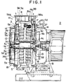
- Fig. 1 is a side view showing a basic construction of the oil-free scroll vacuum pump according to the invention.
- a vacuum pump body 1A has a shaft 11, which has its right end coupled to a drive shaft of a motor 2 and can be rotated by the torque thereof.
- the shaft 11 has a central eccentric portion 11a having a slightly swelled diameter.
- the eccentric shaft portion 11a has opposite end portions rotatably supported via bearings 52 and 53 and packings 15 and 16 in housings 4 and 5.
- the housings 4 and 5 constitute stationary scrolls and cup-shaped, and their peripheral walls function as casings and sealed together via a seal member, forming a sealed space in them.
- the housing 4 has a lap sliding surface 4b perpendicular to its axis and an opening hole is provided on the central portion of a sliding surface 4b, consequently a portion of the shaft 11 which is out of eccentric shaft portion 11a and is not eccentric, is fitted rotatably to the opening hole.
- the housing 4 has a spiral lap 7 with the inner end thereof located near opening hole.
- the lap 7 has a tip groove, in which a self-lubricating tip seal 14 of a fluorine resin or the like is fitted in the tip groove to provide a completely sealed state in contact with an opposed lap sliding surface.
- a discharge port 4c is open in the lap sliding surface 4b near the tip of the lap 7. Compressed gas discharged from the discharge port 4c is exhausted through a discharge passage 4d and discharged to the outside through a discharge opening 9B provided in the outer surface 4a of the housing 4a.
- Three revolving mechanism sets 17 are provided on the peripheral wall of the housing 4 at a circumferential interval of 120 degrees.
- the revolving mechanisms 17 is coupled to a revolving scroll to be described later.
- the peripheral wall 4a of the housing 4 has a suction port 8, which is in turn coupled to a vessel (not shown) to be evacuated, and gas therein is sucked through an opening 8a.
- the housing 5 has a lap sliding surface 5b perpendicular to its axis and a opening hole is provided on the central portion of a sliding surface 5b, consequently a portion of the shaft 11 which is out of eccentric shaft portion 11 and is not eccentric, is fitted rotatably to the opening hole.
- the housing 5 has a spiral lap 6 with the inner end thereof located near opening hole.
- the lap 6 has a tip groove, in which a tip seal 14 is fitted to provide a completely sealed state in contact with an opposed sliding surface.
- a discharge port 5c is open in the lap sliding surface 5b near the inner end of the lap 6. Compressed gas discharged from the discharge port 5c is exhausted through a discharge passage 5d and discharged to the outside through a discharge opening 9A formed in the peripheral wall 5a of the housing 5.
- a revolving scroll 3 is rotatably disposed in a space defined by the housings 4 and 5.
- the revolving scroll 3 has a disc, which has laps 26 and 27 formed on its opposite side surfaces 3d and 3e and engaged with the stationary scroll laps.
- the revolving scroll 3 has a central hole 3a, which is rotatably penetrated by the eccentric portion 11a of the shaft 11.
- the central hole 3a is surrounded by laps 26a and 27a over the entire length of the eccentric shaft portion 11.
- Fans 12 and 13 for cooling the pump are provided on portions of the shaft 11 on the outer sides of the housings 5 and 4.
- Covers 18 and 19 having pluralities of air vent holes, are mounted on the housings 4 and 5 and cover the fans.
- rotation of the shaft 11 causes revolving of the revolving scroll 3 to suck gas from the vessel (not shown).
- the sucked gas is taken in from the outer ends of the stationary scroll laps 6 and 7 by the revolving scroll laps 26 and 27 into sealed spaces, which are defined by the stationary and revolving scroll laps, for compression in these sealed spaces, the compressed gas being discharged through the discharge ports 4c and 5c.
- compressed gas can be exhausted through the discharge passages 5d and 4d each provided for each side (i. e., each of the revolving laps 6 and 7) of the revolving scroll 3. It is thus possible to reduce mechanical loss and improve the efficiency of discharging compressed gas.
- discharge passages 5d and 4d are provided in outer portions 5e and 4e of the stationary scrolls and extend outward from the housings 18 and 19, it is possible to obtain a dry state of operation in the case of connecting a plurality of vacuum pumps as well.
- the eccentric shaft portion 11a penetrating the disc of the revolving scroll 3 in an eccentric relation thereto has its opposite end portions rotatably supported in the stationary scroll side bearings 52 and 53, the eccentric shaft portion is stable with respect to the stationary scrolls.
- the vacuum pump further is free form the above problems of the generation of noise and heat or the durability reduction due to warping and vibrations of the shaft at high rotation speed and non-uniform contact between the stationary and revolving scrolls due to warping of the shaft.
- the fans 12 and 13 for cooling the scroll which are mounted outside of bearing 52, 53, are driven by the same drive source as for the eccentric shaft portion 11a.
- the outer portions 4e and 5e of the both stationary scrolls thus can be cooled from the same drive source 2 as for driving the revolving scrolls 3.
- the bearings and the discharge passages 4d and 5d can be provided in the space between the above fans 12, 13 and the stationary scroll outer portion 5e, 4e, thus it is possible to provide a compact scroll mechanism without reduction of discharging efficiency.
- the spaces between the fans 12 and 13 and the outer portions 4e and 5e of the stationary scrolls extend from the outer peripheries of the bearings 15 and 16 and are open to the outside over 360 degrees except for mounting parts such as frames and housings.
- the discharge passages 5d and 4d thus can be disposed in a range of substantially 360 degrees in the side view of Fig. 1, and a high degree of freedom can be ensured for the disposition of the discharge ports 9Aa and 9Ba.
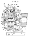
- Fig. 2 is a sectional view showing a second embodiment of the Oil-free scroll vacuum pump according to the invention.
- This embodiment is the same as the preceding embodiment shown in Fig. 1 except for that a diffuser 3b is communicated with the final sealed spaces, which are defined by the revolving and stationary scrolls in communication with the discharge port 4d, and that in lieu of the other discharge port 5d a passage 5g in communication with ejector means is connected to the diffuser 3b.
- the revolving scroll 3 has a central hole 3a, which is rotatably penetrated by the eccentric portion 11a of the shaft 11 noted above, is surrounded by laps 26a and 27a over the entire length of the eccentric portion 11a of the shaft 11.
- the diffuser 3b is provided adjacent to the hole 3a.
- the diffuser 3b is provided with flare-shaped large diameter toward the outer end of lap 26 and with trumpet-shaped small diameter toward the center portion, and it has a small diameter nozzle 3f at its center.
- the diffuser 3b further has a trumpet-shaped portion flaring toward the outer end of the lap 27.
- Holes 3g and 3h communicating with the final sealed paces defined by the stationary and revolving laps are open to the diffuser 3b.
- the peripheral wall 5a of the housing 5 has a suction port 28, which is coupled to an ejector vessel (not shown on drawing) accommodating compressed nitrogen gas, from where the ejector compressed gas in the vessel is led through the suction port 28a.
- a hole 5f is open in a portion of the lap sliding surface 5b near the end of the lap 26, and a passage 5d is led from the hole 5f to the suction port 28 in the peripheral wall 5a of the housing 5.
- the hole 5f and the discharge port 4c may be always communicated with the diffuser 3b. Alternately, they may be communicated with the diffuser 3b in synchronism to the instant when the final sealed chamber are brought to a maximum volume with the revolution of the revolving scroll 3.
- rotation of the shaft 11 causes revolving of the revolving scroll 3 to suck gas from the vessel (not shown).
- the sucked gas is taken from the outer ends of the stationary scrolls lap 6 and 7 in the sealed spaces defined by the revolving scroll laps 26 and 27 to be compressed by the sealed spaces.
- Ejector vessel compressed gas is led by ejector means through the hole 5f into the diffuser 3b.
- the gas taken in the sealed spaces defined by the stationary and revolving scroll laps is compressed, and when the final sealed spaces are communicated with the openings 3g and 3h, the compressed gas is exhausted into the diffuser 3b.
- the compressed gas is discharged together with the ejector vessel compressed gas from the ejector means through the discharge port 4c.
- a double-lap scroll mechanism is constituted by the revolving laps 26 and 27 on the both side surfaces of the disc of the revolving scroll 3, and the eccentric shaft portion 22a penetrating the disc in an eccentric relation thereto has its end portions rotatably supported by the stationary scroll side bearings 52 and 53.
- the stationary scroll outer portions can be cooled by the single drive source 2 for driving the revolving scroll 3, and no extra drive source is need to drive the fans. It is thus possible to simplify the construction and provide a contact scroll mechanism.
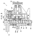
- Fig. 3 is a sectional view showing a third embodiment of the oil-free scroll vacuum pump according to the invention.
- the illustrated oil-free scroll vacuum pump 1C is of a single-lap type and comprises a stationary scroll 30, a revolving scroll 46 and a frame 40 supporting the scrolls at a predetermined position and for revolving.
- the revolving scroll 30 is secured to an end surface of the frame 40.
- the stationary scroll 30 has a peripheral wall 37 defining a recess and a spiral lap 39 extending in the recess, and it further has a discharge port 45 open in a substantially central portion of the recess for discharging compressed gas.
- the peripheral wall 37 has a suction port 44, and a duct 29 is connected to the suction port 44. Gas is led from a vessel (not shown) to the duct 29 in the direction of arrow 50.
- the revolving scroll 46 is accommodated in the recess of the frame 40, and has a lap 51 of substantially the same spiral shape as the lap 39 of the stationary scroll 30.
- the lap 51 extends at right angles from a disc surface in contact with an end surface of the peripheral wall 37.
- the laps 39 and 51 are in engagement with each other.
- Cooling fins 33 and 49 are formed on the back sides of the scrolls 30 and 46 to cool the inner sides of the scrolls by air cooling.
- the scroll laps 39, 51 each have a tip groove formed in the tip facing the opposed scroll, and a self-lubricating tip seal 31 is fitted in the tip groove.
- the mechanism is thus driven by oil-free frictional driving.
- the stationary scroll 30 has a mirror-finish surface, which faces a corresponding mirror-finish surface of the disc of the revolving scroll 46 and has a circular groove formed adjacent to it.
- a ring-like self-lubricating dust seal 32 is fitted in the circular groove, thus maintaining the gas tightness of the sealed inner space defined by the laps 39 and 51 of the revolving and stationary scrolls 46 and 30 from the outside and preventing air and dust particles from being sucked from the outside.
- the frame 40 coaxially supports a main drive crankshaft 41 with a pulley 42 mounted thereon and also supports three driven crankshafts 43 supported at positions at a radial interval of 120 degrees with respect to the axis of the main drive crankshaft 41.
- crankshafts 41 and 43 are rotatably supported in a housing 48 which is integral with the revolving scroll 46. With rotation of the main crankshaft 41, the revolving scroll 46 is revolved about the center of the lap of the stationary scroll 30 with a predetermined radius of revolving without being rotated.
- the stationary scroll 30 has a suction port 36, which is coupled to an ejector vessel (not shown) accommodating nitrogen gas to be sucked through it.
- the suction port 36 is communicated via a passage 35 with a diffuser 34.
- the diffuser 34 has a rear portion coupled to the passage 35 and the discharge port 45, and it has a trumpet-shaped portion flaring from a small diameter nozzle portion 34a toward a large diameter discharge opening 34b.
- rotation of the pulley 42 causes revolving of the revolving scroll 46, whereby gas is sucked form the vessel (not shown) and taken by the outer end of the stationary scroll lap 39 into a sealed space defined by the revolving and stationary scroll laps 51 and 39 for compression in the sealed space.
- the gas taken in the sealed space is compressed, and when the final sealed chamber is communicated with the discharge port 45, the compressed gas is discharged into the diffuser 34.
- the discharged compressed gas is exhausted together with ejector vessel compressed gas through the diffuser discharge opening 34b.
- compressed gas is led to the diffuser for discharging the compressed gas in the vessel to be evacuated from the ejector means, and the compressed gas is exhausted together with the ejector vessel compressed gas.
- Fig. 4 is a sectional view showing a two-stage oil-free scroll vacuum pump according to the invention, which comprises vacuum pumps 1A and 1D connected in series.
- the vacuum pump 1A is a first stage with a discharge port 9A thereof connected via a duct 23 to a suction port 8 of the second stage vacuum pump 1D.
- the first stage vacuum pump 1A has its discharge port 9B coupled via an electromagnetic valve 21 and a duct 24 to the duct 23 and also communicated via an electromagnetic valve 22 to the outside.
- the electromagnetic valves 21 and 22 While the pressure of the first stage compressed gas is above 1,000 to 100 Pa, the electromagnetic valves 21 and 22 are "open", and compressed gas under a high pressure in the first stage pump 1A in an initial stage from the start, is exhausted through the electromagnetic valve 22 to the outside lest it should be taken in the second stage pump 1D.
- the compressed gas pressure may be determined by measuring the pressure in the vessel (not shown) to be evacuated.
- the electromagnetic valves 21 and 22 may be controlled according to a map an exhausting characteristic based on the volume of the vessel and the operating performance of the first stage pump 1A, the map being stored in a controller 10.
- the controller 10 has an output terminal which is connected to control terminals of the control valves 21 and 22 for on-off control thereof, thus controlling drive sources connected to driving source of the first and second stage pumps 1A and 1D.
- the controller 10 holds the electromagnetic valves 21 ad 22 "open", and drives the first stage pump 1A. Gas is thus sucked from the vessel (not shown) to be evacuated through the suction Port 8 into the first stage pump 1A and compressed in this pump, and the high compressed gas being compressed by the first stage pump 1A is discharged through the discharge ports 9A and 9B.
- the compressed gas discharged from the discharge port 9A is led through the electromagnetic valve 21 and also is discharged together with compressed gas from the discharge port 9B through the electromagnetic valve 22 to the outside.
- the second stage pump is driven to start compression of the compressed gas led from the first stage pump.
- the gas compressed in the first stage pump is not in a low vacuum degree viscous range, thus giving rise to no problem of heat generation in the second stage pump due to high temperature.
- the sealed vessel to be evacuated is connected to the suction port of the first stage pump, whereof the gas pressure in the seal vessel is close to the atmospheric pressure in an initial stage operation, and the sucked gas is already compressed to a high pressure in the compression process in the first stage pump.
- the compressed gas under the high pressure is thus discharged to the outside from the first stage pump via the valve means without being supplied to the second stage pump.
- valve means When the pressure of the compressed gas from the first stage pump becomes lower than a predetermined pressure, the valve means is closed, so that the compressed gas from the first stage pump is further compressed by the second stage pump.
- the first and second stage pumps can be rotated by different drive sources, it is possible to give the drive sources optimum rotations based on the compressed gas loads which in turn correspond to the compression ratios of the first and second stage pumps.
- the sole first stage pump can be driven to exhaust the compressed gas via the valve means to the outside, and the second stage pump can be driven after the first stage pump compressed gas pressure has become lower than the atmospheric pressure. It is thus possible to obtain economical operation.
- the compressed gas from the vacuum pump is exhausted by supplying compressed gas from the ejector means to the diffuser, it is possible to from a vacuum pump permitting the compression efficiency improvement and to provide an oil-free vacuum pump, which harmful gas from the vessel, having been concentrated, if any, in the compression process for evacuation, can be diluted.
Landscapes
- Engineering & Computer Science (AREA)
- Mechanical Engineering (AREA)
- General Engineering & Computer Science (AREA)
- Rotary Pumps (AREA)
- Applications Or Details Of Rotary Compressors (AREA)
Abstract
A double-lap oil-free scroll vacuum pump is disclosed, which comprises a revolving scroll 3 with revolving laps 26 and 27 provided on both sides of a disc, stationary scrolls provided on their surfaces 4b, 5b facing each surface 3d, 3e of said disc with stationary laps 6, 7 in engagement with the revolving laps 26, 27, said revolving laps 26, 27 being arranged in frictional contact with said surfaces 4b, 5b of the stationary scrolls, and a rotationary drive shaft 11 penetrating the stationary and revolving scrolls and eccentrically fitted in the disc of the revolving scroll 3, wherein the rotational drive shaft 11 drives the revolving scroll 3 to cause discharge of compressed gas from a last compression chamber. A housing 19 is mounted on the outer sides of the stationary scrolls, and accommodates a drive source of the rotational drive shaft 11. Discharge passages 4d and 5d are provided for discharging compressed gas from the sides of the surfaces 3d and 3e of the revolving scroll 3. The discharge passages 4d and 5d extend outwardly from the housing 19.
Description
- This invention relates to scroll vacuum pumps permitting the compression efficiency improvement and, more particularly, to oil-free scroll vacuum pumps for improving the fluid discharging efficiency.
- Evacuation of a vessel is usually done by connecting a vacuum pump to an exhausting port of the vessel and exhausting air and other gases from the vessel with the vacuum pump.
- In a low vacuum pressure exhausting system, a vacuum pump unit is formed by accommodating one oil rotary pump in one vessel. In a high vacuum pump system, a wet vacuum pump unit is formed by combining an oil diffusion pump and a oil rotary pump.
- In these units, oil is evaporated by a heater in the boiler, and the steam thus generated is blown out to compress diffused gas. The compressed gas is further compressed by the rotary pump up to the atmospheric pressure and discharged to the outside.
- These units constitute a wet exhausting system and have a problem that oil produced again as the vapor which is attached to the inner walls of the unit, is evaporated again and flows back into the vessel, that is, the reverse flow, a cold cap, a buffle, a trap or the like is used for cooling, thus complicating the construction. In addition, chlorine, fluorine or like gas reacts with and denature the oil, thus increasing the rotational resistance, reducing the capacity and making the inspection and maintenance more cumbersome.
- Accordingly, dry exhausting systems are desired, and recently oil-free scroll pumps have attracting attention as vacuum pump.
- The scroll vacuum pump has stationary and revolving scroll laps, and the volume of sealed space defined between the two laps can be varied by causing revolution of the revolving scroll relative to the stationary scroll without causing rotation of the revolving scroll.
- In this operation, the point of contact between the two laps defining the sealed space, which functions as the compression chamber, is gradually shifted toward the pump center.
- With the revolution of the revolving scroll about the center the stationary scroll lap with a constant radius of revolution, gas entering the pump through a suction port thereof is led around the peripheral end of the revolving scroll lap and taken in a sealed space defined between the two laps.
- As the sealed space is gradually reduced in volume and shifted toward the center with the revolution of the revolving scroll, the gas taken in the sealed space is compressed, and is discharged to the outside when the sealed space is brought into communication with a discharge port.
- The scroll vacuum pump is either of a single lap type, in which the revolving scroll has a revolving scroll lap on one surface of its disc of revolving scroll, or a double lap type, in which the revolving scroll has two revolving scroll laps each provided on each of the both surfaces of its disc. This double lap type vacuum pump is disclosed in Japanese Laid-Open Patent Publication No. 57-203801 (prior art 1).
- As shown in Fig. 6, the prior art 1 discloses a scroll mechanism, which has a
suction port 206 for supplying fluid to sealed spaces on both sides of arevolving scroll 201 and adischarge port 207 for discharging compressed fluid. - In this type of vacuum scroll pump, the
laps scroll 201 may have only one half the lap height in the case of the single lap type to process the same volume of compressed fluid. This means that when forming the laps by machining, the depth of grinding from the lap tip to the mirror finish surface can be reduced, thus a revolving scroll having satisfactory processibility can be provided. - In addition, it is possible to reduce the
discharge port 207 for discharging compressed fluid to the outside of the scroll mechanism so as to increase the efficiency of compressing fluid. - The
discharge port 207 is open to one sealedspace 200, and compressed fluid therein 200 can be discharged through abovedischarge port 207. However, compressed fluid in the other sealedspace 210 is led through a smalldiameter lead hole 203 formed in a central part of therevolving scroll 201 before being discharged through the discharge port which is provided on the other side of the stationary scroll. Therefore, the exhausting efficiency is reduced due to mechanical loss when the compressed fluid is discharged. - The mechanical loss may be reduced by sufficiently increasing the diameter of the
lead hole 203 in the revolvingscroll 201. In this case, however, the efficiency of compression is reduced. - It is thus desirable to provide a discharge port on each side of the revolving scroll.
- Japanese Laid-Open Patent Publication No. 59-15690 (prior art 2) discloses a scroll fluid apparatus, in which a suction port is provided on each side of a revolving scroll and compressed fluid is discharged through a single discharge port.
- As shown in Fig. 5, the
prior art 2 discloses a sealedvessel 101, in which a lower and an upperstationary scroll - A
suction duct 113 is connected to ahole 116 of theupper scroll 108, and asuction duct 114 is connected to anopening 117 of the lowerstationary scroll 107. - A
revolving scroll 112 is interposed between the upper and lowerstationary scrolls - A
shaft 103 of amotor 102 is disposed in the sealedvessel 101, and has adrive gear 104 secured to it. - Two
crankshafts 106 are provided, which have drivengears 105 to which torque of thedrive gear 104 is transferred. - The
crankshafts 106 are supported in bearings provided in the twostationary scrolls side revolving scroll 112. - The upper and lower
stationary scrolls lower discharge port 111 and 110, respectively. With the rotation of thedrive shaft 103 the doubleside revolving scroll 112 is revolved, and compressed fluid discharged from thedischarge ports 110 and 111 is led through adischarge duct 115 provided on the sealedvessel 101. - In the above construction according to the
prior art 2, drive power is transferred from thedrive shaft 103 of thedrive motor 102 via thedrive gear 104 and drivengears 105 to the twocrankshafts - In addition, drive power is transmitted from the eccentric shaft portions 106a of the two
crankshafts scroll 112, such a high level technique as prevention of interference between the eccentric shaft portions 106a is necessary. - In the meantime, to meet a recent demand for higher vacuum it is desired to reduce operation time for obtaining a desired vacuum.
- In a low compression ratio vacuum pump, a long time is taken for evacuation, and a high compression ratio vacuum pump is desired.
- The compression ratio can be increased by increasing the turns number of spiral scrolls. Increasing the turns number, however, increases the scroll size, thus giving rise to the problems of the generation of vibrations of revolution due to flexion of the shaft in high speed rotation and of noise or heat due to non-uniform contact between stationary and revolving scrolls, by which the durability is reduced.
- To solve these problems, it has been proposed to a method to use two vacuum pumps, in which the scroll size is not large and the turns number is small, drive together these pumps by connecting the suction end of the second stage one to the discharge duct of the first stage one.
- However, in such a series pump drive system, in which fluid having been compressed in the first stage is further compressed in the second stage, oil that may be present during the flow of fluid from the first to the second stage would lead to durability deterioration of the vacuum pumps.
- From this standpoint, in the
prior art 2, as shown in Fig. 5, compressed fluid exhausted from the upper andlower discharge port 111, 110 fills a lower space in theframe 118, in which themotor 102 is disposed, and is discharged to the outside when the pressure in the space becomes higher than the external pressure. - Therefore, lubricant or the like on the
shaft 13 may contaminate themotor 102, supports thereof and other parts. - Japanese Laid-Open Patent Publication No. 6-66271 shows a scroll compressor using a diffuser.
- As shown in Fig. 7, this scroll compressor has a
diffuser 312, which extends from a compressedfluid discharge port 373 formed in a portion of astationary scroll 348 corresponding to afinal compression chamber 300 defined by astationary scroll lap 346 and a revolvingscroll lap 342. Compressed fluid is led through thediffuser 312 before being exhausted from anopening 375, by which efficiency of compressor is improved. - The above related art enables compressing gas and exhausting the compressed gas. However, in application to a vacuum pump, gases which are harmful to the body of the man may be generated in dependence on the using purpose of the vessel to be evacuated; for example, in application to a process of semiconductor manufacture harmful gases to the man's body are generated. Such gases cannot be made harmless.
- In view of the foregoing, it is an object of the invention to provide an oil-free scroll vacuum pump, which has a dry scroll mechanism having a double lap revolving scroll, and in which the compressed gas exhausting efficiency is not reduced.
- Another object of the invention is to provide an oil-free scroll vacuum pump, which is free from partial load due to slant framework on the revolving scroll interposed between both stationary scroll laps and interference among components accompanying the revolving scroll.
- A further object of the invention is to provide an oil-free scroll vacuum pump, which has high cooling efficiency and compact construction.
- According to a first aspect of the invention, a double-lap oil-free vacuum pump is provided, which comprises a revolving scroll with revolving laps provided on both sides of a disc, and stationary scrolls each with a stationary lap formed on the surface facing each surface of the disc of the stationary scroll, the stationary lap being in engagement with each of the revolving laps, the stationary scrolls supporting the revolving scrolls in frictional contact therewith, the stationary scrolls each having a disc with a discharge passage for discharging compressed fluid on each side of the revolving scroll.
- As shown in Figs. 1 and 2, a double-lap oil-free scroll vacuum pump is constructed, which comprises a
revolving scroll 3 with revolvinglaps stationary lap surface surface stationary scroll 3, thestationary lap laps - The stationary scrolls each have a disc with a
discharge passage - Compressed air is thus exhausted from
discharge passages scroll 3, and the efficiency of exhausting compressed gas is improved. - According to a second aspect of the invention, an oil-free scroll vacuum pump for compressing gas in a pump body and discharging the compressed gas through a diffuser to the outside of the pump body is provided, which comprises ejector means for forcing to lead ejector compressed gas into the diffuser to discharge compressed gas from the pump body.
- It is effective means according to the second aspect of the invention to provide the diffuser between a final compression chamber defined by a stationary scroll and a revolving scroll and the discharge passage.
- As shown in Fig. 2, to discharge the compressed gas having been compressed from the pump body to the outside thereof, a
diffuser 3b in communication with adischarge port 4c is communicated with alead passage 3 connected with an ejector vessel to lead compressed gas of ejection vessel therefrom through the lead passage. - Final compression chambers defined by the stationary and revolving scrolls are communicated with the
diffuser 3b viaopenings - As shown in Fig. 3, to discharge compressed gas from the pump body to the outside, a
diffuser 34 in communication with adischarge port 34b is communicated with alead passage 35 in communication with the ejector vessel to lead compressed gas of ejector vessel through the lead passage. - Final compression chamber defined by the stationary and revolving scrolls are communicated with the
diffuser 34 via dischargedhole 45. - With this construction, when the ejector compressed gas from the ejector means which flows into the diffuser expand at the outlet of the diffuser, it causes a pressure reduction in the diffuser.
- Compressed gas from the vacuum pump is thus sucked by a negative pressure produced by the pressure reduction noted above and discharged into the diffuser, and exhausted together with the ejector compressed gas from the ejector means through the diffuser outlet to the outside of the vacuum pump body.
- With the ejector vessel compressed gas from ejector means introduced by nitrogen gas (N2) into the diffuser, any harmful gas which may be contained in the vessel can be diluted by the nitrogen gas even though it is concentrated in the compression process for evacuation.
- According to a third aspect of the invention, a double-lap oil-free scroll vacuum pump is provided, which comprises a revolving scroll with revolving laps provided on both sides of a disc, and stationary scrolls each with a stationary lap formed on the surface facing each surface of the disc of the stationary scroll, the stationary lap being in engagement with each of the revolving laps, on which the stationary scrolls supporting the revolving scrolls in frictional contact therewith, an eccentric shaft portion being fitted in the revolving scroll disc in an eccentric relation thereto, and both side portions of the eccentric shaft portion being rotationally supported in stationary scroll side bearings.
- It is effective means according to the third aspect of the invention to provide fans, which are mounted outside the bearings and rotated by the same drive source as for the eccentric shaft portion and cool the stationary scrolls.
- It is effective means according to the third aspect of the invention to provide a discharge passage for discharging compressed gas between each fan and the outer surface of each stationary scroll.
- As shown in Fig. 1, an eccentric shaft portion 11a is in the disc of the revolving
scroll 3 in an eccentric relation thereto, with its both sides rotationally supported inbearings stationary scrolls - Cooling
fans bearings stationary scrolls Discharge passages fan - With this construction, the eccentric shaft portion is stable with respect to the stationary scrolls, and the pump is free from the problems of the generation of vibrations of revolution due to flexion of the shaft in high speed rotation or of noise and heat, or reduction of the durability due to non-uniform contact between the stationary and revolving scrolls resulting from the flexion of the shaft or other causes.
- With the
fans - As shown, the eccentric shaft portion which is fitted in the disc of the revolving scroll has its end portions rotatably supported in the stationary scroll side bearings, the cooling fans are mounted outside the bearings and are rotated by the same drive source as for the eccentric shaft portion, and the discharge passages for discharging compressed gas are each provided between each fan and the outer surface of each stationary scroll.
- With this construction, the bearings and the discharge passages can be provided in the spaces between the fans and the outer surfaces of the stationary scrolls, and it is thus possible to provide a scroll mechanism, which is free from exhausting efficiency reduction and compact in construction.
- Besides, the spaces between the fans and the outer surfaces of the stationary scrolls extend from the outer periphery of each of the bearings and are open toward the outside over 360 degrees except for such mounting members as frames and housings. A high freedom of design is thus provided for the disposition of the discharge port.
- According to a fourth aspect of the invention, a double-lap oil-free scroll mechanism is provided, which comprises a double-lap oil-free scroll mechanism including a revolving scroll with revolving laps provided on both sides of a disc of revolving scroll, and an eccentric shaft being fitted in the revolving scroll disc in an eccentric relation thereto for driving revolving scroll, both side portions of the eccentric shaft being rotationally supported in stationary scroll side bearings, and in which fans are mounted outside the bearing and rotated by the same drive source as for the eccentric shaft for cooling the stationary scrolls, and thus it is an oil-free scroll vacuum pump which a lead passage of above ejection is provided between the above fans and the outer surface of above stationary scroll.
- With this scroll mechanism of the double-lap type, in which the both side of the eccentric shaft portion fitted in the revolving scroll disc in an eccentric relation thereto are rotatably supported in the stationary scroll side bearings, the eccentric shaft portion is made stable with respect to the stationary scrolls, and the pump is thus free form the problems of the generation of vibration of revolution due to flexion of the shaft in high speed rotation and noise and heat or durability reduction due to non-uniform contact between the stationary and revolving scrolls resulting from flexion of shaft or other causes.
- With the fans mounted outside the bearings and rotated by the same drive source as for the eccentric shaft portion for cooling the stationary scrolls, the outer surfaces of the both stationary scrolls are cooled from the single drive source for driving the revolving scroll. No extra drive source for driving the fans is thus unnecessary, and it is possible to simplify the construction and provide a compact scroll mechanism.
- With the ejector passages provided between the fans and the outer surfaces of the stationary scrolls, a compact scroll mechanism can be provided.
- According to a fifth aspect of the invention, an oil-free scroll vacuum pump is provided, which comprises a plurality of vacuum pump bodies connected in series by valve means, and in which the vacuum pump bodies each comprise a revolving scroll with revolving laps provided on both sides of a disc, stationary scrolls each with stationary lap formed on the surface facing each surface of the disc of the revolving scroll, the stationary lap being in engagement with each of the revolving laps, the stationary scrolls supporting the revolving scrolls being in frictional contact therewith, rotational drive means penetrating the stationary and revolving scrolls and eccentrically fitted in the revolving scroll disc, a housing mounted on the outside surface of the stationary scrolls and accommodating the rotational drive means, and a discharge passage for discharging compressed gas from each side of the revolving scroll to the disc of each of the stationary scroll, and the valve means is selectively controlled for an action of communicating to the outside with a space between the discharge passage of a preceding stage vacuum pump and suction port of a succeeding stage vacuum pump, and an action for connecting in series a preceding vacuum pump and a succeeding stage vacuum pump.
- According to the fifth aspect of the invention, as shown in Fig. 4, a plurality of oil-free scroll vacuum pumps are connected in series, and valve means 21 and 22 are provided for selectively controlling an action of communicating a space between the discharge passage of a first stage vacuum pump body 1A and a
suction port 8 of a second stage vacuum pump body 1D, and an action for connecting in series the first and second stage vacuum pump bodies 1A and 1D to each other. - When a vessel to be evacuated is connected to the
suction port 8 of the preceding stage pump body 1A, in an initial stage of the operation the pressure in the vessel is close to the atmospheric pressure, the sucked gas is brought to a high pressure in a compression process in the preceding stage pump body 1A. - However, the compressed gas under high pressure is not supplied to the succeeding stage pump body 1D is discharged through the valve means 21 and 22 to the outside.
- When the pressure of the compressed gas from the preceding stage pump body 1A becomes lower than a predetermined pressure, the valve means 21 and 22 are closed, and the compressed gas from the pump body 1A is supplied to the preceding stage pump body 1D for further compression.
- Thus, no compression gas under a pressure higher than the atmospheric pressure is sucked into the second stage pump body 1D. No excessive compression and heating thus take place in the second stage pump body 1D, and neither durability reduction of the second stage pump body 1D nor burn thereof to cause damage thereto results from heat generation that might otherwise result from a high pressure.
- In addition, since independent drive sources rotate a plurality of vacuum pumps, for instance the first and second vacuum pumps, they can be given optimum rotations corresponding to compressed gas loads based on compression ratios of the first and second pumps.
- When the pressure of the compressed gas in the first stage pump exceeds atmospheric pressure in an initial stage of evacuation of a vessel, only the first stage pump is driven to exhaust the compressed gas through the valve means to the outside in a low viscous flow range corresponding to a low range of vacuum in the vessel, and when the compressed gas pressure in the first stage pump becomes lower than the atmospheric pressure, the second stage pump may be driven for economical driving.
- Since the discharge passages for exhausting the dry system compressed gas are each provided in each of the stationary scroll discs, they can extend to the outside of the housings mounted on the outer surfaces of the stationary scrolls. Thus, no lubricant or the like is introduced into compressed gas from the revolving scroll drive source, and it is possible to realize a high compression ratio by connecting the first and second stage pumps in series.
-
- Fig. 1 is a sectional view showing a basic embodiment of the oil-free scroll vacuum pump according to the invention;
- Fig. 2 is a schematic view showing a second embodiment of the oil-free scroll vacuum pump according to the invention;
- Fig. 3 is a schematic view showing a third embodiment of the oil-free scroll vacuum pump according to the invention;
- Fig. 4 is a schematic view showing a fourth embodiment of the oil-free scroll vacuum pump composed of 2 steps according to the invention;
- Fig. 5 is a view showing prior art 1 related to the double-lap scroll mechanism;
- Fig. 6 is a view showing
prior art 2 related to the double-lap scroll mechanism; and - Fig. 7 is a view showing prior art related to the scroll mechanism using a diffuser.
- Embodiments of the invention will now be described in detail. It is to be construed that unless particularly described, the sizes, shapes, relative dispositions, etc. of the constituent parts mentioned in the description of the embodiments have no sense of limiting the scope of the invention but are merely exemplary.
- Fig. 1 is a side view showing a basic construction of the oil-free scroll vacuum pump according to the invention.
- Referring to Fig. 1, a vacuum pump body 1A has a shaft 11, which has its right end coupled to a drive shaft of a
motor 2 and can be rotated by the torque thereof. - The shaft 11 has a central eccentric portion 11a having a slightly swelled diameter. The eccentric shaft portion 11a has opposite end portions rotatably supported via
bearings packings housings - The
housings - The
housing 4 has alap sliding surface 4b perpendicular to its axis and an opening hole is provided on the central portion of a slidingsurface 4b, consequently a portion of the shaft 11 which is out of eccentric shaft portion 11a and is not eccentric, is fitted rotatably to the opening hole. - The
housing 4 has aspiral lap 7 with the inner end thereof located near opening hole. Thelap 7 has a tip groove, in which a self-lubricatingtip seal 14 of a fluorine resin or the like is fitted in the tip groove to provide a completely sealed state in contact with an opposed lap sliding surface. - A
discharge port 4c is open in thelap sliding surface 4b near the tip of thelap 7. Compressed gas discharged from thedischarge port 4c is exhausted through adischarge passage 4d and discharged to the outside through adischarge opening 9B provided in theouter surface 4a of thehousing 4a. - Three revolving mechanism sets 17 are provided on the peripheral wall of the
housing 4 at a circumferential interval of 120 degrees. - The revolving
mechanisms 17 is coupled to a revolving scroll to be described later. - The
peripheral wall 4a of thehousing 4 has asuction port 8, which is in turn coupled to a vessel (not shown) to be evacuated, and gas therein is sucked through anopening 8a. - The
housing 5 has alap sliding surface 5b perpendicular to its axis and a opening hole is provided on the central portion of a slidingsurface 5b, consequently a portion of the shaft 11 which is out of eccentric shaft portion 11 and is not eccentric, is fitted rotatably to the opening hole. - The
housing 5 has aspiral lap 6 with the inner end thereof located near opening hole. Thelap 6 has a tip groove, in which atip seal 14 is fitted to provide a completely sealed state in contact with an opposed sliding surface. - A
discharge port 5c is open in thelap sliding surface 5b near the inner end of thelap 6. Compressed gas discharged from thedischarge port 5c is exhausted through adischarge passage 5d and discharged to the outside through adischarge opening 9A formed in theperipheral wall 5a of thehousing 5. - A revolving
scroll 3 is rotatably disposed in a space defined by thehousings - The revolving
scroll 3 has a disc, which haslaps - The revolving
scroll 3 has acentral hole 3a, which is rotatably penetrated by the eccentric portion 11a of the shaft 11. Thecentral hole 3a is surrounded bylaps -
Fans housings Covers housings - The revolving
mechanisms 17 described above, which are supported at one end on thehousing 4, are supported at the other end on the outer periphery of the revolvingscroll 3 to cause revolving of the revolving scroll about an axis of revolving, which is eccentric with respect to the stationary scrolls. - The operation of the embodiment having the above construction will be described.
- Referring to Fig. 1, rotation of the shaft 11 causes revolving of the revolving
scroll 3 to suck gas from the vessel (not shown). - The sucked gas is taken in from the outer ends of the
stationary scroll laps scroll laps discharge ports - In this embodiment, compressed gas can be exhausted through the
discharge passages laps 6 and 7) of the revolvingscroll 3. It is thus possible to reduce mechanical loss and improve the efficiency of discharging compressed gas. - Since the
discharge passages outer portions housings - Since the eccentric shaft portion 11a penetrating the disc of the revolving
scroll 3 in an eccentric relation thereto, has its opposite end portions rotatably supported in the stationaryscroll side bearings - The vacuum pump further is free form the above problems of the generation of noise and heat or the durability reduction due to warping and vibrations of the shaft at high rotation speed and non-uniform contact between the stationary and revolving scrolls due to warping of the shaft.
- The
fans outer portions same drive source 2 as for driving the revolving scrolls 3. - Thus, no extra drive source is needed to drive the fans, the construction can be simplified, and it is possible to provide a compact scroll mechanism.
- Since the
discharge passages fans discharge passages above fans outer portion - In this embodiment, the spaces between the
fans outer portions bearings discharge passages - Fig. 2 is a sectional view showing a second embodiment of the Oil-free scroll vacuum pump according to the invention.
- This embodiment is the same as the preceding embodiment shown in Fig. 1 except for that a
diffuser 3b is communicated with the final sealed spaces, which are defined by the revolving and stationary scrolls in communication with thedischarge port 4d, and that in lieu of theother discharge port 5d a passage 5g in communication with ejector means is connected to thediffuser 3b. - For the remainder of the construction, the embodiment is the same as the preceding embodiment shown in Fig. 1, and like parts are designated by like reference numerals and symbols.
- The revolving
scroll 3 has acentral hole 3a, which is rotatably penetrated by the eccentric portion 11a of the shaft 11 noted above, is surrounded bylaps - The
diffuser 3b is provided adjacent to thehole 3a. - The
diffuser 3b is provided with flare-shaped large diameter toward the outer end oflap 26 and with trumpet-shaped small diameter toward the center portion, and it has asmall diameter nozzle 3f at its center. - The
diffuser 3b further has a trumpet-shaped portion flaring toward the outer end of thelap 27. -
Holes diffuser 3b. - The
peripheral wall 5a of thehousing 5 has asuction port 28, which is coupled to an ejector vessel (not shown on drawing) accommodating compressed nitrogen gas, from where the ejector compressed gas in the vessel is led through thesuction port 28a. - A hole 5f is open in a portion of the
lap sliding surface 5b near the end of thelap 26, and apassage 5d is led from the hole 5f to thesuction port 28 in theperipheral wall 5a of thehousing 5. - The hole 5f and the
discharge port 4c may be always communicated with thediffuser 3b. Alternately, they may be communicated with thediffuser 3b in synchronism to the instant when the final sealed chamber are brought to a maximum volume with the revolution of the revolvingscroll 3. - Instead of forming the central
small diameter nozzle 3f of thediffuser 3b, it is possible to set such that the lap end facing the hole 5f is a large diameter, a portion extending from this large diameter portion to the discharge opening 4c is progressively reduced in diameter, and thedischarge passage 4d extending from the discharge opening 4c has a large diameter. - The operation of the second embodiment having the above construction will now be described.
- Referring to Fig. 2, rotation of the shaft 11 causes revolving of the revolving
scroll 3 to suck gas from the vessel (not shown). - The sucked gas is taken from the outer ends of the
stationary scrolls lap scroll laps - Ejector vessel compressed gas is led by ejector means through the hole 5f into the
diffuser 3b. - The gas taken in the sealed spaces defined by the stationary and revolving scroll laps is compressed, and when the final sealed spaces are communicated with the
openings diffuser 3b. - At this time, the compressed gas is discharged together with the ejector vessel compressed gas from the ejector means through the
discharge port 4c. - As shown, in the second embodiment with nitrogen gas (N2) ejected as the ejector vessel compressed gas from the ejector means into the diffuser, harmful gas from the vessel to be evacuated and concentrated, if any, in the compression process for evacuation, can be diluted by the nitrogen gas.
- In the second embodiment, again a double-lap scroll mechanism is constituted by the revolving
laps scroll 3, and the eccentric shaft portion 22a penetrating the disc in an eccentric relation thereto has its end portions rotatably supported by the stationaryscroll side bearings - Again the
fans bearings - With this double-lap scroll mechanism, in which the opposite end portions of the eccentric shaft portion 11a penetrating the disc of the revolving
scroll 3 in an eccentric relation thereto are rotatably supported in the stationaryscroll side bearings - With the
fans bearings single drive source 2 for driving the revolvingscroll 3, and no extra drive source is need to drive the fans. It is thus possible to simplify the construction and provide a contact scroll mechanism. - With the ejector passage 5g provided between the
fan 12 and theouter portion 5e of thestationary scroll 5, thebearing 53 and the elector passage 5f may be provided in the space between the above fan and stationary scroll outer portion, and it is possible to provide a compact scroll mechanism.
Fig. 3 is a sectional view showing a third embodiment of the oil-free scroll vacuum pump according to the invention. - The illustrated oil-free scroll vacuum pump 1C is of a single-lap type and comprises a
stationary scroll 30, a revolvingscroll 46 and aframe 40 supporting the scrolls at a predetermined position and for revolving. - The revolving
scroll 30 is secured to an end surface of theframe 40. - The
stationary scroll 30 has a peripheral wall 37 defining a recess and aspiral lap 39 extending in the recess, and it further has adischarge port 45 open in a substantially central portion of the recess for discharging compressed gas. - The peripheral wall 37 has a
suction port 44, and aduct 29 is connected to thesuction port 44. Gas is led from a vessel (not shown) to theduct 29 in the direction ofarrow 50. - The revolving
scroll 46 is accommodated in the recess of theframe 40, and has a lap 51 of substantially the same spiral shape as thelap 39 of thestationary scroll 30. - The lap 51 extends at right angles from a disc surface in contact with an end surface of the peripheral wall 37.
- The
laps 39 and 51 are in engagement with each other. - Cooling
fins scrolls - The
scroll laps 39, 51 each have a tip groove formed in the tip facing the opposed scroll, and a self-lubricatingtip seal 31 is fitted in the tip groove. The mechanism is thus driven by oil-free frictional driving. - The
stationary scroll 30 has a mirror-finish surface, which faces a corresponding mirror-finish surface of the disc of the revolvingscroll 46 and has a circular groove formed adjacent to it. A ring-like self-lubricatingdust seal 32 is fitted in the circular groove, thus maintaining the gas tightness of the sealed inner space defined by thelaps 39 and 51 of the revolving andstationary scrolls - The
frame 40 coaxially supports amain drive crankshaft 41 with apulley 42 mounted thereon and also supports three drivencrankshafts 43 supported at positions at a radial interval of 120 degrees with respect to the axis of themain drive crankshaft 41. - The
crankshafts housing 48 which is integral with the revolvingscroll 46. With rotation of themain crankshaft 41, the revolvingscroll 46 is revolved about the center of the lap of thestationary scroll 30 with a predetermined radius of revolving without being rotated. - The
stationary scroll 30 has asuction port 36, which is coupled to an ejector vessel (not shown) accommodating nitrogen gas to be sucked through it. Thesuction port 36 is communicated via apassage 35 with adiffuser 34. - The
diffuser 34 has a rear portion coupled to thepassage 35 and thedischarge port 45, and it has a trumpet-shaped portion flaring from a smalldiameter nozzle portion 34a toward a largediameter discharge opening 34b. - The operation of the third embodiment having the above construction will now be described.
- Referring to Fig. 3, rotation of the
pulley 42 causes revolving of the revolvingscroll 46, whereby gas is sucked form the vessel (not shown) and taken by the outer end of thestationary scroll lap 39 into a sealed space defined by the revolving andstationary scroll laps 51 and 39 for compression in the sealed space. - In the meantime, ejector vessel compressed gas is led from ejector means through the
passage 35 into thediffuser 34. - The gas taken in the sealed space is compressed, and when the final sealed chamber is communicated with the
discharge port 45, the compressed gas is discharged into thediffuser 34. - The discharged compressed gas is exhausted together with ejector vessel compressed gas through the
diffuser discharge opening 34b. - As shown in the third embodiment, compressed gas is led to the diffuser for discharging the compressed gas in the vessel to be evacuated from the ejector means, and the compressed gas is exhausted together with the ejector vessel compressed gas.
- When compressed gas led from the ejector means being led to a first stage of the diffuser is expanded in a second stage thereof, the compressed gas by the vacuum pump is sucked by the pressure reduction generated in the diffuser first state and discharged to this first stage, and is discharged from the diffuser second stage together with the compressed gas from the ejector means.
- Thus, like the second embodiment with nitrogen gas (N2) supplied as compressed gas from the ejector means to the diffuser, harmful gas from the vessel, even though having been compressed in the compression process for evacuation, can be diluted by the nitrogen gas.
- Fig. 4 is a sectional view showing a two-stage oil-free scroll vacuum pump according to the invention, which comprises vacuum pumps 1A and 1D connected in series.
- Referring to Fig. 4, the vacuum pump 1A is a first stage with a
discharge port 9A thereof connected via aduct 23 to asuction port 8 of the second stage vacuum pump 1D. The first stage vacuum pump 1A has itsdischarge port 9B coupled via anelectromagnetic valve 21 and aduct 24 to theduct 23 and also communicated via anelectromagnetic valve 22 to the outside. - While the pressure of the first stage compressed gas is above 1,000 to 100 Pa, the
electromagnetic valves electromagnetic valve 22 to the outside lest it should be taken in the second stage pump 1D. - When the compressed gas pressure noted above becomes lower than 1,000 to 100 Pa, the
electromagnetic valves - The compressed gas pressure may be determined by measuring the pressure in the vessel (not shown) to be evacuated. Alternatively, the
electromagnetic valves controller 10. - The
controller 10 has an output terminal which is connected to control terminals of thecontrol valves - In the embodiment having the construction shown in Fig. 4 as described above, for an initial stage of driving, the
controller 10 holds theelectromagnetic valves 21ad 22 "open", and drives the first stage pump 1A. Gas is thus sucked from the vessel (not shown) to be evacuated through thesuction Port 8 into the first stage pump 1A and compressed in this pump, and the high compressed gas being compressed by the first stage pump 1A is discharged through thedischarge ports - The compressed gas discharged from the
discharge port 9A is led through theelectromagnetic valve 21 and also is discharged together with compressed gas from thedischarge port 9B through theelectromagnetic valve 22 to the outside. - When the compressed gas pressure below lower than 1,000 to 100 Pa, the
electromagnetic valves - Since the
electromagnetic valve 21 is closed, gas discharged from thedischarge port 9B, having been compressed in the stationary and revolvingscrolls 7 and 27 (Fig. 1), is led together with gas discharged from thedischarge port 5c, having been compressed by the stationary and revolvingscrolls discharge port 9A and theduct 23 to the second stage pump 1D. - While in the above description of operation the
electromagnetic valves electromagnetic valve 22. In this case, compressed gas discharged from thedischarge port 9B is led through theelectromagnetic valve 21 to thepassage 23 and thence together with compressed gas discharged from thedischarge port 9A to the second stage pump 1D. - In synchronism to this moment, the second stage pump is driven to start compression of the compressed gas led from the first stage pump.
- At this time, the gas compressed in the first stage pump is not in a low vacuum degree viscous range, thus giving rise to no problem of heat generation in the second stage pump due to high temperature.
- Since the compressed gas is further compressed in the second stage pump 1D, it is possible to realize a high compression ratio.
- Since the discharge passage for exhausting the dry system compressed gas extends outwardly of the housing, no lubricant or the like is introduced by the revolving scroll drive source, and it is thus possible to connect the first and second pumps in series and realize a high compression ratio.
- Since a plurality of oil-free scroll vacuum pumps are connected in series and valve means in communication with the outside is provided in the discharge passage, the sealed vessel to be evacuated is connected to the suction port of the first stage pump, whereof the gas pressure in the seal vessel is close to the atmospheric pressure in an initial stage operation, and the sucked gas is already compressed to a high pressure in the compression process in the first stage pump. The compressed gas under the high pressure is thus discharged to the outside from the first stage pump via the valve means without being supplied to the second stage pump.
- When the pressure of the compressed gas from the first stage pump becomes lower than a predetermined pressure, the valve means is closed, so that the compressed gas from the first stage pump is further compressed by the second stage pump.
- Thus, no compressed gas under a pressure higher than the atmospheric pressure is sucked into the second stage pump, giving rise to no possibility of heat generation by excessive compression in the second stage pump. Without heat generation due to high pressure, neither the durability of the vacuum pump is deteriorated, nor the burn of the pump and damage thereto takes place.
- Since a plurality of vacuum pumps are connected, the first and second stage pumps can be rotated by different drive sources, it is possible to give the drive sources optimum rotations based on the compressed gas loads which in turn correspond to the compression ratios of the first and second stage pumps.
- In the initial stage of evacuating the vessel, in which time the first stage pump compressed gas pressure is higher than the atmospheric pressure, that is, in a viscosity region in which the degree of vacuum of the vessel is low, the sole first stage pump can be driven to exhaust the compressed gas via the valve means to the outside, and the second stage pump can be driven after the first stage pump compressed gas pressure has become lower than the atmospheric pressure. It is thus possible to obtain economical operation.
- As has been described in the foregoing, according to the invention it is possible to provide an oil-free scroll vacuum pump, in which the efficiency of exhausting compressed gas is not deteriorated.
- In addition, since the compressed gas from the vacuum pump is exhausted by supplying compressed gas from the ejector means to the diffuser, it is possible to from a vacuum pump permitting the compression efficiency improvement and to provide an oil-free vacuum pump, which harmful gas from the vessel, having been concentrated, if any, in the compression process for evacuation, can be diluted.
Claims (8)
- A double-lap oil-free scroll vacuum pump comprising:a revolving scroll (3) with revolving laps (26, 27) provided on both sides of a disc; andstationary scrolls each with a stationary lap (6, 7) formed on its surface (4b, 5b) facing a respective surface (3d, 3e) of said disc, said stationary lap being in engagement with a respective revolving lap;said stationary scrolls supporting said revolving scroll in frictional contact therewith;said stationary scrolls each having a disc with a discharge passage (4d, 5d) for discharging compressed fluid on each side of said revolving scroll.
- An oil-free scroll vacuum pump for compressing gas in a pump body and discharging the compressed gas through a diffuser (3b, 34) to the outside of said pump body, comprising:ejector means (5g, 35) for forcing to lead ejector compressed gas into said diffuser to discharge compressed gas from said pump body.
- An oil-free scroll vacuum pump according to claim 2, wherein said diffuser (3b, 34) is provided between a final compression chamber defined by a stationary scroll and a revolving scroll (3) and a discharge passage (4d).
- A double-lap oil-free scroll vacuum pump comprising:a revolving scroll (3) with revolving laps (26, 27) provided on both sides of a disc; andstationary scrolls each with a stationary lap (6, 7) formed on its surface (4b, 5b) facing a respective surface (3d, 3e) of said disc, said stationary lap being in engagement with a respective revolving lap;said stationary scrolls supporting said revolving scroll in frictional contact therewith;an eccentric shaft portion (11a) being fitted in said revolving scroll disc in an eccentric relation thereto, both side portions of said eccentric shaft portion being rotationally supported in stationary scroll side bearings (52, 53).
- An oil-free scroll vacuum pump according to claim 4, wherein fans (12, 13) are mounted outside said bearings (52, 53), said fans being rotated by the same drive source (2) as for said eccentric shaft portion, and cooling said stationary scrolls.
- An oil-free scroll vacuum pump according to claim 5, wherein a discharge passage (4d, 5d) for discharging compressed gas is provided between each said fan (12, 13) and the outer surface of each said stationary scroll.
- An oil-free scroll vacuum pump comprising a double-lap oil-free scroll mechanism including a revolving scroll (3) with revolving laps (26, 27) provided on both sides of a disc of the revolving scroll, and an eccentric shaft portion (11a) being fitted in said revolving scroll disc in an eccentric relation thereto for driving the revolving scroll, both side portions of said eccentric shaft portion being rotationally supported in stationary scroll side bearings (52, 53), wherein:fans (12, 13) are mounted outside said bearings, said fans being rotated by the same drive source (2) as for said eccentric shaft portion, and cooling said stationary scrolls; andejector passages (4d, 5d, 5g) are provided between said fans and the outer surfaces of said stationary scroll.
- An oil-free scroll vacuum pump comprising a plurality of vacuum pump bodies (1A, 1D) connected in series by valve means (21, 22), wherein:said vacuum pump bodies each comprise:a revolving scroll (3) with revolving laps (26, 27) provided on both sides of a disc;stationary scrolls each with a stationary lap (6, 7) formed on the surface (4b, 5b) facing a respective surface (3d, 3e) of said disc of said revolving scroll, said stationary lap being in engagement with a respective revolving lap, said stationary scrolls supporting said revolving scroll in frictional contact therewith;rotational drive means (11) penetrating said stationary and revolving scrolls and eccentrically fitted in said revolving scroll disc;a housing (4, 5) mounted on the outer surfaces of said stationary scrolls and accommodating said rotational drive means; anda discharge passage (4d, 5d, 9A, 9B) for discharging compressed gas from each side of said revolving scroll to a disc of each of said stationary scrolls; andsaid valve means (21, 22) is provided for selectively controlling:an action of communicating the outside with a space (23, 24, 25) between the discharge passage (9A, 9B) of a preceding stage vacuum pump (1A) and a suction port (8) of a succeeding stage vacuum pump (1B); andan action for connecting in series a preceding vacuum pump (1A) and a succeeding stage vacuum pump (1B).
Applications Claiming Priority (4)
| Application Number | Priority Date | Filing Date | Title |
|---|---|---|---|
| JP104192/96 | 1996-03-29 | ||
| JP10419296A JP3884101B2 (en) | 1996-03-29 | 1996-03-29 | Oil-free scroll vacuum pump |
| JP103431/96 | 1996-03-29 | ||
| JP10343196A JP3815747B2 (en) | 1996-03-29 | 1996-03-29 | Oil-free vacuum pump |
Publications (2)
| Publication Number | Publication Date |
|---|---|
| EP0798463A2 true EP0798463A2 (en) | 1997-10-01 |
| EP0798463A3 EP0798463A3 (en) | 1998-02-25 |
Family
ID=26444067
Family Applications (1)
| Application Number | Title | Priority Date | Filing Date |
|---|---|---|---|
| EP97105399A Withdrawn EP0798463A3 (en) | 1996-03-29 | 1997-04-01 | Oil-free scroll vacuum pump |
Country Status (1)
| Country | Link |
|---|---|
| EP (1) | EP0798463A3 (en) |
Cited By (12)
| Publication number | Priority date | Publication date | Assignee | Title |
|---|---|---|---|---|
| CN103573627A (en) * | 2012-08-07 | 2014-02-12 | 思科涡旋科技(杭州)有限公司 | Multilevel floating vortex vacuum pumps and usage method thereof |
| DE102014117400A1 (en) | 2014-11-27 | 2016-06-02 | Pfeiffer Vacuum Gmbh | Scroll vacuum pump |
| EP3153708A1 (en) | 2015-10-06 | 2017-04-12 | Pfeiffer Vacuum Gmbh | Scroll pump and method for operating a scroll pump |
| CN109185127A (en) * | 2018-07-28 | 2019-01-11 | 西安交通大学 | A kind of cooling structure of oil-free turbo-compressor |
| EP3647599A3 (en) * | 2019-10-07 | 2020-07-22 | Pfeiffer Vacuum Gmbh | Vacuum pump, scroll pump and method of manufacturing same |
| CN111486093A (en) * | 2020-05-09 | 2020-08-04 | 江阴华西节能技术有限公司 | A dry vacuum host for the pharmaceutical industry |
| CN112196789A (en) * | 2020-08-24 | 2021-01-08 | 河北昊方新能源科技有限公司 | An oil-free scroll air pump |
| EP3739166A3 (en) * | 2019-10-07 | 2021-03-17 | Pfeiffer Vacuum Gmbh | Vacuum pump, scroll pump and method of manufacturing same and check valve |
| DE102020134469A1 (en) | 2020-12-21 | 2022-06-23 | OET GmbH | Scroll compressor for generating oil-free compressed air |
| CN116412125A (en) * | 2021-12-31 | 2023-07-11 | 广东美的白色家电技术创新中心有限公司 | Compressor, temperature control equipment, control method for temperature control equipment, and related equipment |
| CN116677601A (en) * | 2023-05-31 | 2023-09-01 | 西安交通大学 | A compression vacuum integrated oil-free scroll machine |
| WO2025044627A1 (en) * | 2023-08-30 | 2025-03-06 | 沈阳海龟医疗科技有限公司 | Floating oil-free vacuum scroll compressor |
Family Cites Families (9)
| Publication number | Priority date | Publication date | Assignee | Title |
|---|---|---|---|---|
| FR1121079A (en) * | 1955-02-03 | 1956-07-20 | Volumetric turbine | |
| DE3721611A1 (en) * | 1987-06-30 | 1989-01-19 | Alcatel Hochvakuumtechnik Gmbh | MECHANICAL VACUUM PUMP WITH A SPRING-LOADED CHECK VALVE |
| FR2647853A1 (en) * | 1989-06-05 | 1990-12-07 | Cit Alcatel | DRY PRIMARY PUMP WITH TWO FLOORS |
| DE4129897A1 (en) * | 1991-09-09 | 1993-03-11 | Koterewa Katharina | Control for interlinking of multistage vacuum pumps - has connection channel between pump stages with stroke valve, coupled to discharge valve |
| US5342183A (en) * | 1992-07-13 | 1994-08-30 | Copeland Corporation | Scroll compressor with discharge diffuser |
| DE59206958D1 (en) * | 1992-07-20 | 1996-09-26 | Aginfor Ag | Rotating spiral pump |
| DE4341716C1 (en) * | 1993-12-03 | 1995-03-09 | Mannesmann Ag | Air-cooled vane compressor |
| EP0687815B1 (en) * | 1994-06-17 | 1998-11-18 | Asuka Japan Co., Ltd. | Scroll type fluid machine |
| JP3423514B2 (en) * | 1995-11-30 | 2003-07-07 | アネスト岩田株式会社 | Scroll fluid machine |
-
1997
- 1997-04-01 EP EP97105399A patent/EP0798463A3/en not_active Withdrawn
Cited By (20)
| Publication number | Priority date | Publication date | Assignee | Title |
|---|---|---|---|---|
| CN103573627A (en) * | 2012-08-07 | 2014-02-12 | 思科涡旋科技(杭州)有限公司 | Multilevel floating vortex vacuum pumps and usage method thereof |
| DE102014117400A1 (en) | 2014-11-27 | 2016-06-02 | Pfeiffer Vacuum Gmbh | Scroll vacuum pump |
| EP3045728A1 (en) | 2014-11-27 | 2016-07-20 | Pfeiffer Vacuum GmbH | Spiral vacuum pump |
| EP3153708A1 (en) | 2015-10-06 | 2017-04-12 | Pfeiffer Vacuum Gmbh | Scroll pump and method for operating a scroll pump |
| EP3508727A1 (en) | 2015-10-06 | 2019-07-10 | Pfeiffer Vacuum Gmbh | Scroll pump and method for operating a scroll pump |
| CN109185127A (en) * | 2018-07-28 | 2019-01-11 | 西安交通大学 | A kind of cooling structure of oil-free turbo-compressor |
| CN109185127B (en) * | 2018-07-28 | 2020-04-28 | 西安交通大学 | Cooling structure of oil-free scroll compressor |
| EP3739166A3 (en) * | 2019-10-07 | 2021-03-17 | Pfeiffer Vacuum Gmbh | Vacuum pump, scroll pump and method of manufacturing same and check valve |
| EP3647599A3 (en) * | 2019-10-07 | 2020-07-22 | Pfeiffer Vacuum Gmbh | Vacuum pump, scroll pump and method of manufacturing same |
| EP3647599B1 (en) | 2019-10-07 | 2021-12-22 | Pfeiffer Vacuum Gmbh | Vacuum pump, scroll pump and method of manufacturing same |
| EP3974655A3 (en) * | 2019-10-07 | 2022-06-29 | Pfeiffer Vacuum GmbH | Vacuum pump, scroll pump and method of manufacturing same and check valve |
| US11773849B2 (en) | 2019-10-07 | 2023-10-03 | Pfeiffer Vacuum Gmbh | Vacuum pump, scroll pump, and manufacturing method for such |
| CN111486093A (en) * | 2020-05-09 | 2020-08-04 | 江阴华西节能技术有限公司 | A dry vacuum host for the pharmaceutical industry |
| CN112196789A (en) * | 2020-08-24 | 2021-01-08 | 河北昊方新能源科技有限公司 | An oil-free scroll air pump |
| DE102020134469A1 (en) | 2020-12-21 | 2022-06-23 | OET GmbH | Scroll compressor for generating oil-free compressed air |
| WO2022136157A1 (en) | 2020-12-21 | 2022-06-30 | OET GmbH | Scroll compressor for generating oil-free compressed air |
| US12215690B2 (en) | 2020-12-21 | 2025-02-04 | OET GmbH | Scroll compressor for generating oil-free compressed air |
| CN116412125A (en) * | 2021-12-31 | 2023-07-11 | 广东美的白色家电技术创新中心有限公司 | Compressor, temperature control equipment, control method for temperature control equipment, and related equipment |
| CN116677601A (en) * | 2023-05-31 | 2023-09-01 | 西安交通大学 | A compression vacuum integrated oil-free scroll machine |
| WO2025044627A1 (en) * | 2023-08-30 | 2025-03-06 | 沈阳海龟医疗科技有限公司 | Floating oil-free vacuum scroll compressor |
Also Published As
| Publication number | Publication date |
|---|---|
| EP0798463A3 (en) | 1998-02-25 |
Similar Documents
| Publication | Publication Date | Title |
|---|---|---|
| EP1101943B1 (en) | Control of a two-stage vacuum pump | |
| JP3985051B2 (en) | Double wrap dry scroll vacuum pump | |
| EP0798463A2 (en) | Oil-free scroll vacuum pump | |
| US5931650A (en) | Hermetic electric scroll compressor having a lubricating passage in the orbiting scroll | |
| AU2009316974B2 (en) | Screw compressor | |
| US7086844B2 (en) | Multi-stage scroll fluid machine having a set a seal elements between compression sections | |
| EP0863313A1 (en) | Two stage scroll compressor | |
| JPH08261182A (en) | Scroll type fluid machinery | |
| US5069605A (en) | Scroll fluid machine having a sealing member radially inwardly of a thrust bearing | |
| JP2003343459A (en) | Scroll fluid machine and oxygen generating device | |
| EP1690007B1 (en) | Two stage scroll vacuum pump | |
| EP0931939B1 (en) | Vacuum pump | |
| US6638040B2 (en) | Dry vacuum pump | |
| JP3884101B2 (en) | Oil-free scroll vacuum pump | |
| JP2618825B2 (en) | Intercoolerless air-cooled 4-stage roots vacuum pump | |
| JP7212926B2 (en) | scroll vacuum pump | |
| JP2002174174A (en) | Vacuum exhaust device | |
| JPH08240180A (en) | Oilless vacuum pump device and control method therefor | |
| KR100253250B1 (en) | Turbo compressor | |
| KR20210016220A (en) | Electro-compressor | |
| KR100320192B1 (en) | Gasbearing structure for turbo compressor | |
| KR20000008563A (en) | Thrust bearing structure of turbo compressor | |
| JPH07332263A (en) | Oilless scroll type vacuum pump | |
| KR100304562B1 (en) | Turbo compressor | |
| KR100304563B1 (en) | Turbo compressor |
Legal Events
| Date | Code | Title | Description |
|---|---|---|---|
| PUAI | Public reference made under article 153(3) epc to a published international application that has entered the european phase |
Free format text: ORIGINAL CODE: 0009012 |
|
| AK | Designated contracting states |
Kind code of ref document: A2 Designated state(s): DE FR GB IT |
|
| PUAL | Search report despatched |
Free format text: ORIGINAL CODE: 0009013 |
|
| AK | Designated contracting states |
Kind code of ref document: A3 Designated state(s): DE FR GB IT |
|
| 17P | Request for examination filed |
Effective date: 19980727 |
|
| STAA | Information on the status of an ep patent application or granted ep patent |
Free format text: STATUS: THE APPLICATION HAS BEEN WITHDRAWN |
|
| 18W | Application withdrawn |
Withdrawal date: 20000308 |