EP0799520B1 - Elektromagnetischer krafterzeuger - Google Patents
Elektromagnetischer krafterzeuger Download PDFInfo
- Publication number
- EP0799520B1 EP0799520B1 EP95944207A EP95944207A EP0799520B1 EP 0799520 B1 EP0799520 B1 EP 0799520B1 EP 95944207 A EP95944207 A EP 95944207A EP 95944207 A EP95944207 A EP 95944207A EP 0799520 B1 EP0799520 B1 EP 0799520B1
- Authority
- EP
- European Patent Office
- Prior art keywords
- cores
- moveable
- pole faces
- force generator
- force
- Prior art date
- Legal status (The legal status is an assumption and is not a legal conclusion. Google has not performed a legal analysis and makes no representation as to the accuracy of the status listed.)
- Expired - Lifetime
Links
- 230000005291 magnetic effect Effects 0.000 claims description 16
- 238000004804 winding Methods 0.000 claims description 11
- 239000000725 suspension Substances 0.000 claims description 8
- XEEYBQQBJWHFJM-UHFFFAOYSA-N Iron Chemical compound [Fe] XEEYBQQBJWHFJM-UHFFFAOYSA-N 0.000 claims description 6
- 230000007246 mechanism Effects 0.000 claims description 6
- 229910052761 rare earth metal Inorganic materials 0.000 claims description 5
- 150000002910 rare earth metals Chemical class 0.000 claims description 5
- 229910052742 iron Inorganic materials 0.000 claims description 3
- 238000003475 lamination Methods 0.000 claims description 3
- 239000000463 material Substances 0.000 claims 3
- 230000001747 exhibiting effect Effects 0.000 claims 2
- 230000004907 flux Effects 0.000 description 24
- 230000005284 excitation Effects 0.000 description 11
- 238000012360 testing method Methods 0.000 description 4
- 239000000696 magnetic material Substances 0.000 description 3
- 239000004411 aluminium Substances 0.000 description 2
- XAGFODPZIPBFFR-UHFFFAOYSA-N aluminium Chemical compound [Al] XAGFODPZIPBFFR-UHFFFAOYSA-N 0.000 description 2
- 229910052782 aluminium Inorganic materials 0.000 description 2
- 238000010586 diagram Methods 0.000 description 2
- QJVKUMXDEUEQLH-UHFFFAOYSA-N [B].[Fe].[Nd] Chemical compound [B].[Fe].[Nd] QJVKUMXDEUEQLH-UHFFFAOYSA-N 0.000 description 1
- 230000008901 benefit Effects 0.000 description 1
- KPLQYGBQNPPQGA-UHFFFAOYSA-N cobalt samarium Chemical compound [Co].[Sm] KPLQYGBQNPPQGA-UHFFFAOYSA-N 0.000 description 1
- 238000010276 construction Methods 0.000 description 1
- 230000005347 demagnetization Effects 0.000 description 1
- 239000003822 epoxy resin Substances 0.000 description 1
- 230000005294 ferromagnetic effect Effects 0.000 description 1
- 229910001172 neodymium magnet Inorganic materials 0.000 description 1
- 230000035699 permeability Effects 0.000 description 1
- 229920000647 polyepoxide Polymers 0.000 description 1
- 230000004044 response Effects 0.000 description 1
- 229910000938 samarium–cobalt magnet Inorganic materials 0.000 description 1
Images


Classifications
-
- H—ELECTRICITY
- H02—GENERATION; CONVERSION OR DISTRIBUTION OF ELECTRIC POWER
- H02K—DYNAMO-ELECTRIC MACHINES
- H02K33/00—Motors with reciprocating, oscillating or vibrating magnet, armature or coil system
- H02K33/16—Motors with reciprocating, oscillating or vibrating magnet, armature or coil system with polarised armatures moving in alternate directions by reversal or energisation of a single coil system
Definitions
- the present invention relates to an electromagnetic force generator and more particularly to such a generator or actuator which allows the connection of only a relatively small mass to the structure to be driven.
- Such force generators are commonly referred to as shakers.
- the bistable actuator comprises a permanent magnet assembly secured to an armature shaft and a pair of core elements axially disposed on either side of the permanent magnet assembly.
- the cores have axially opposed inner and outer annular extensions defined in each core by a central axial opening which supports the armature shaft and an annular recess in which is received an electrical coil.
- the permanent magnet assembly comprises inner and outer annular axially magnetized permanent magnets radially spaced by a ferromagnetic ring so as to be aligned with the inner and outer core extensions.
- the transducer applying the force should have bandwidth, linear response, and should couple relatively little additional mass to the structure which is to be driven. While some prior designs have achieved reasonable linearity and broad bandwidth, they have typically exhibited a relatively large inertial mass at the output point, i.e., the flange by means of which the transducer is coupled to the structure under test.
- an electromagnetic force generator comprising:
- the force generator of the present invention employs a output element which is driven with respect to an inertial mass.
- the mass associated with the output element is relatively small as compared with the inertial mass.
- Core 11 may be made up on soft iron laminations and provides, at each end, transversely facing pole faces 13 and 15. In the orientation illustrated, the pole faces are directed downwardly. While the pole faces are shown as being coplanar with the length of the core 11, it should be understood that they might project downwardly.
- a second elongate magnetic core 21 Extending parallel to the first magnetic core and spaced therefrom is a second elongate magnetic core 21 having, at each end transversely facing pole faces 23 and 25. Pole faces 23 and 25 are upwardly facing and are aligned with and facing the corresponding pole faces of the first core 11. It should be understood that the term "elongate" is used in the present disclosure basically to establish an orientation useful in describing the relative locations of subsequently described components and thus no inference should be drawn as to relative length, width and depth.
- a winding 31 is provided for energizing the core 11 and a similar winding 33 is provided for energizing the core 21.
- each pair of aligned pole faces is a relatively moveable core, i.e., moveable core 27 between faces 13 and 23 and moveable core 29 between faces 15 and 25.
- the direction of relative movement is vertical in the orientation shown in Figure 1 and thus there is a gap of variable width between each of the pole faces on the elongate cores and the respective moveable core.
- the relatively moveable cores 27 and 29 are mounted on a light weight, e.g., aluminium, frame 37 by means of which they can be attached to a structure, designated by reference character 39, to which a vibrating force is to be applied.
- a compliant mechanical connection is provided between the relatively moveable cores and the first and second cores by means of a suspension which is illustrated in the Figure 1 simply by springs 41 and 43.
- Magnet 35 Mounted between the first and second cores 11 and 21 is a magnet 35 which, as described hereinafter, provides a steady state or d.c. bias to the moveable cores 27 and 29.
- Magnet 35 is preferably a permanent magnet and is preferably constructed of a so called rare earth magnetic material which provides a relatively high reluctance in relation to its coercive force and which is relatively resistant to demagnetization. Examples of such rare earth magnetic materials are neodymium iron boron and samarium cobalt.
- the magnet 35 extends to a point closely adjacent each of the moveable cores 27 and 29 there thus being a sliding gap between the permanent magnet and each moveable core. According the widths of the sliding gaps will remain of essentially constant width as the cores 27 and 29 move in the vertical direction as illustrated.
- the permanent magnet 35 provides an essentially constant or d.c. bias flux linking each of the moveable cores 27 and 29 with the elongate cores 11 and 21. This flux is indicated by the dotted arrows 45 and 47 in Figure 1.
- the winding 31 and 33 are employed to generate a variable or a.c. flux which links the elongate cores 11 and 13 and the relatively moveable cores 27 and 29 but which does not pass through the permanent magnet 35.
- This flux path is indicated by the dotted arrow 49 in Figure 1.
- the basic magnetic circuit is shown as an ohmic and voltage arrangement to illustrate the distribution of reluctances and magnetic potentials.
- the excitations by the windings 31 and 33 are shown as a.c. voltage sources, 61 and 62 respectively, provided, and the magnet 35 is shown as a d.c. source or battery 63.
- the reluctances of the gaps are shown as resistance elements, the variable gaps between the moveable cores and the elongate cores being shown as variable resistances R1-R4 and the sliding gaps as resistances R5-R6.
- the reluctance of the rare earth magnet is represented by resistance R7.
- the reluctances of the laminated cores themselves are not shown since they have much lower reluctances than either the air gaps or the magnet.
- the excitation windings operate in phase so that the resulting flux passes through the gaps R1-R4, which form an outer flux path.
- No a.c. or excitation flux passes through the central path which comprises the sliding gaps R5 and R6 and the magnet R7.
- the reaction mass moves the corresponding gap sizes vary and do their reluctances.
- the upper gaps R1 and R3 have nominally matching reluctances, as do gaps R2 and R4 and thus there is no potential difference across the central magnet path and hence no a.c. excitation flux through the magnet.
- slight mismatch between the variable gaps can occur and will lead to a potential difference but even in this case the passage of excitation flux through the permanent magnet is low due to the high reluctance R7 of the central magnet path.
- the bias flux generated by the magnet enters the outer flux path and flows in opposite directions through the upper and lower gap pairs thus adding or subtracting to the excitation flux.
- the reluctance of the magnet path R5, R6 and R7 is made as high as practical which helps to reduce the undesirable negative stiffness of the magnetic circuit.
- the flux paths are indicated in Figure 1 by the arrows 45, 47 and 49.
- the force calculation can be derived as follows.
- the excitation flux 49 forms an outer loop.
- the bias flux 45 forms an upper inner loop and the bias flux 47 forms a lower inner loop.
- the air gaps across which the force is developed are R1 and R3 (upper pair) and R2 and R4 (lower pair). With the reaction mass centered within its range of travel, which is its average position, the size of all the variable gaps is the same.
- the bias fluxes 45 and 47 are therefore the same.
- the flux in the upper pair of gaps R1 and R3 is the difference between excitation and the bias flux.
- the flux in the lower pair of gaps R2 and R4 is similarly the sum of the excitation and bias flux.
- the net force produced by this force generator is the difference between the force at the upper pair of gaps minus the force at the lower pair of gaps.
- the net force is thus linearly related to the excitation flux.
- the elongate cores and their windings are identified by the same reference characters as in Figure 1.
- a magnetic structure made up of two blocks of rare earth magnetic material, identified by reference characters 61 and 63, separated by a magnetically permeable iron block 65 which is used for mechanical attachment. These three elements are cemented together by an epoxy resin and essentially function in the same manner as the single magnet of Fig. 1.
- the elongate cores with their windings, together with the permanent magnet structure are secured together by side frames 67 and 69 which are provided with respective mounting arms 71 and 73.
- the side frame pieces, 67 and 69 are bridged by a bottom plate 74.
- the various fasteners which secure these elements together are not shown in the interest of clarity of illustration.
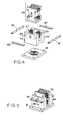
- the configuration of the complete subassembly is indicated by reference character 75 in Fig. 4. As will be understood, this subassembly constitutes and comprises an inertial mass which is reacted against to generate the force being applied to the structure under test.
- the relatively moveable cores are identified by the same reference characters, 27 and 29, as in Fig. 1. These relatively moveable cores are mounted between light weight, e.g. aluminium, end plates 77 and 79 which are in turn mounted on a light weight base plate or mounting flange 81.
- This output assembly or frame is identified by reference character 84 in Figures 4 and 5.
- the resilient suspension for supporting inertial mass 75 within the output frame 84 comprises a pair of flat springs 85 and 87, and a diaphragm type spring 88 mounted within an opening in the base plate 81.
- Mounting arms 71 and 73 are attached to the mid points of the springs and the ends of the springs pass through slots in the ends of pivot rods 90 and 91 which are journaled in the end plates 77 and 79.
- a stud 92, extending from the bottom plate 74 to the mid-point of the diaphragm spring 88 maintains the orientation of the inertial mass with respect to the mounting frame.
Landscapes
- Engineering & Computer Science (AREA)
- Power Engineering (AREA)
- Reciprocating, Oscillating Or Vibrating Motors (AREA)
- Linear Motors (AREA)
Claims (7)
- Elektromagnetischer Krafterzeuger miteinem ersten länglichen Magnetkern (11) mit einer in Querrichtung zeigenden Polschuhfläche (13, 15) an jedem Ende,einem zweiten länglichen Magnetkern (21), der in einem festgelegten Abstand von dem ersten Kern (11) und im wesentlichen parallel zu diesem angeordnet ist und an jedem Ende eine in Querrichtung zeigende Polschuhfläche (23, 25) aufweist, die jeweils auf die entsprechende Polschuhfläche (13, 15) des ersten Kerns (11) ausgerichtet ist,einem relativ-beweglichen Magnetkern (27, 29) zwischen jedem Paar der aufeinander ausgerichteten Polschuhflächen (13, 15, 23, 25), der in einer zwischen den betreffenden aufeinander ausgerichteten Polschuhflächen (13, 15, 23, 25) verlaufenden Richtung beweglich ist,einem Magneten (35), der in festgelegter relativer Lage zwischen dem ersten und dem zweiten Kern (11, 21) befestigt und entlang einer Achse gepolt ist, die im wesentlichen parallel zu einer Länge des ersten und des zweiten Kerns liegt, und der an jedem seiner Enden bis zu einer Stelle verläuft, die an die relativ-beweglichen Kerne (27, 29) angrenzt, so daß jeweils ein Schiebespalt gebildet wird,einer Halterung (37), welche die beweglichen Kerne (27, 29) mit einer Baugruppe (39) verbindet, auf die die Kraft aufgebracht werden soll,einem ersten Federungsmechanismus (41, 43), der eine federnde mechanische Verbindung zwischen den relativ-beweglichen Kernen (27, 29) und dem ersten und dem zweiten Kern (11, 21) bildet,einem zweiten Federungsmechanismus (88), der die Ausrichtung der Trägheitsmasse in Bezug auf den Befestigungsrahmen aufrechterhält, undWicklungen (31, 33), die jeweils um den ersten bzw. den zweiten Kern (11, 21) herum angeordnet sind, wobei durch Anlegen eines Wechselstroms an die Wicklungen jeweils eine entsprechende Vibrationskraft zwischen den beweglichen Kernen (27, 29) und dem ersten und dem zweiten Kern (11, 21) erzeugt wird.
- Elektromagnetischer Krafterzeuger nach Anspruch 1, wobei der erste und der zweite Kern (11, 21) aus Lamellen aufgebaut sind, die aus einem Material mit relativ geringer Reluktanz bestehen.
- Elektromagnetischer Krafterzeuger nach Anspruch 2, wobei die Lamellen Eisen enthalten.
- Elektromagnetischer Krafterzeuger nach Anspruch 1, wobei der Magnet (35) ein Dauermagnet ist, der ein Material mit relativ hoher Reluktanz aufweist.
- Elektromagnetischer Krafterzeuger nach Anspruch 4, wobei das Material des Dauermagneten ein Seltenerd-Magnetmaterial aufweist.
- Elektromagnetischer Krafterzeuger nach Anspruch 1, wobei der erste Aufhängungsmechanismus (41, 43) zwei Federn aufweist, die die Bewegung der beweglichen Kerne (27, 29) zwischen den zugehörigen Polschuhflächen (13, 15, 23, 25) des ersten und des zweiten Kerns (11, 21) ermöglichen.
- Elektromagnetischer Krafterzeuger nach Anspruch 1, wobei der zweite Aufhängungsmechanismus (88) eine Feder aufweist, die bestrebt ist, die beweglichen Kerne (27, 29) zwischen den zugehörigen Polschuhflächen (13, 15, 23, 25) des ersten und des zweiten Kerns (11, 21) nominell zu zentrieren.
Applications Claiming Priority (3)
| Application Number | Priority Date | Filing Date | Title |
|---|---|---|---|
| US362133 | 1994-12-22 | ||
| US08/362,133 US5587615A (en) | 1994-12-22 | 1994-12-22 | Electromagnetic force generator |
| PCT/US1995/016791 WO1996019862A1 (en) | 1994-12-22 | 1995-12-21 | Electromagnetic force generator |
Publications (3)
| Publication Number | Publication Date |
|---|---|
| EP0799520A1 EP0799520A1 (de) | 1997-10-08 |
| EP0799520A4 EP0799520A4 (de) | 1998-03-18 |
| EP0799520B1 true EP0799520B1 (de) | 1999-08-25 |
Family
ID=23424811
Family Applications (1)
| Application Number | Title | Priority Date | Filing Date |
|---|---|---|---|
| EP95944207A Expired - Lifetime EP0799520B1 (de) | 1994-12-22 | 1995-12-21 | Elektromagnetischer krafterzeuger |
Country Status (6)
| Country | Link |
|---|---|
| US (1) | US5587615A (de) |
| EP (1) | EP0799520B1 (de) |
| JP (1) | JPH10511536A (de) |
| AU (1) | AU4606896A (de) |
| DE (1) | DE69511727T2 (de) |
| WO (1) | WO1996019862A1 (de) |
Families Citing this family (42)
| Publication number | Priority date | Publication date | Assignee | Title |
|---|---|---|---|---|
| US5802191A (en) * | 1995-01-06 | 1998-09-01 | Guenther; Godehard A. | Loudspeakers, systems, and components thereof |
| WO1997038242A1 (en) * | 1996-04-08 | 1997-10-16 | Delta Tooling Co., Ltd. | Magnetic spring having damping characteristics and vibration mechanism having same |
| JP3725272B2 (ja) * | 1996-12-27 | 2005-12-07 | 株式会社デルタツーリング | 振動発生機構 |
| JPH1130274A (ja) * | 1997-05-15 | 1999-02-02 | Delta Tsuuring:Kk | 磁気バネを有する振動機構 |
| KR100281474B1 (ko) | 1997-05-16 | 2001-02-01 | 후지타 히토시 | 자기스프링을구비한에너지출력기구 |
| JP3560450B2 (ja) * | 1997-10-29 | 2004-09-02 | アルプス電気株式会社 | ゲーム機用操作装置 |
| DE19807181A1 (de) * | 1998-02-20 | 1999-08-26 | Bayerische Motoren Werke Ag | Elektromagnetische Schwinganker-Vorrichtung, insbesondere als Aktuator für ein Gaswechselventil einer Kraft- oder Arbeitsmaschine |
| GB9804584D0 (en) | 1998-03-04 | 1998-04-29 | Trolley Scan Pty Limited | Identification of objects by a reader |
| US6059274A (en) * | 1998-05-04 | 2000-05-09 | Gte Internetworking Incorporated | Vibration reduction system using impedance regulated active mounts and method for reducing vibration |
| US8588457B2 (en) | 1999-08-13 | 2013-11-19 | Dr. G Licensing, Llc | Low cost motor design for rare-earth-magnet loudspeakers |
| JP2002530967A (ja) * | 1998-11-13 | 2002-09-17 | エイ グエンサー ゴードハード | 希土類磁石ラウドスピーカーのための低コストのモーター設計 |
| AU6636700A (en) | 1999-08-13 | 2001-03-13 | Godehard A. Guenther | Low cost broad range loudspeaker and system |
| US6262500B1 (en) * | 1999-10-05 | 2001-07-17 | Teikoku Tsushin Kogyo Co., Ltd. | Vibration generator |
| US20020150275A1 (en) * | 2000-06-27 | 2002-10-17 | Guenther Godehard A. | Low profile speaker and system |
| US6611606B2 (en) * | 2000-06-27 | 2003-08-26 | Godehard A. Guenther | Compact high performance speaker |
| US6993147B2 (en) * | 2000-08-14 | 2006-01-31 | Guenther Godehard A | Low cost broad range loudspeaker and system |
| US6914351B2 (en) | 2003-07-02 | 2005-07-05 | Tiax Llc | Linear electrical machine for electric power generation or motive drive |
| EP1790192A4 (de) * | 2004-09-09 | 2010-06-02 | Godehard A Guenther | Lautsprecher und systeme |
| US20060238055A1 (en) * | 2005-04-23 | 2006-10-26 | Danford Tiras J | Magnetic motor |
| GB2429337B (en) * | 2005-08-15 | 2009-10-14 | Perpetuum Ltd | An electromechanical generator for converting mechanical vibrational energy into electrical energy |
| US8189840B2 (en) | 2007-05-23 | 2012-05-29 | Soundmatters International, Inc. | Loudspeaker and electronic devices incorporating same |
| US20080298163A1 (en) * | 2007-06-01 | 2008-12-04 | Jean-Louis Pessin | Vibration Assisted Mixer |
| US8428297B2 (en) * | 2009-02-27 | 2013-04-23 | Technology Properties Limited | Acoustic transducer |
| JP6155470B2 (ja) * | 2011-12-09 | 2017-07-05 | パナソニックIpマネジメント株式会社 | 発電装置 |
| EP2883088B1 (de) | 2012-08-13 | 2022-03-02 | Applied Physical Sciences Corp. | Kohärente schallquelle für seismische untersuchungen im meer |
| US9562982B1 (en) | 2012-08-13 | 2017-02-07 | Applied Physical Sciences Corp. | Coherent sound source for marine seismic surveys |
| US10404150B2 (en) | 2017-01-12 | 2019-09-03 | United States Of America As Represented By The Secretary Of The Navy | Low profile kinetic energy harvester |
| US10848044B1 (en) | 2017-08-14 | 2020-11-24 | The Government Of The United States Of America, As Represented By The Secretary Of The Navy | Linear electromagnetic actuator |
| US10930838B1 (en) | 2017-09-27 | 2021-02-23 | The Unites States of America, as represented by the Secretary of the Navy | Magnetostrictive actuator with center bias |
| US10998487B1 (en) | 2017-09-27 | 2021-05-04 | The United States Of America, As Represented By The Secretary Of The Navy | Linear magnetostrictive actuator |
| CN209313677U (zh) * | 2018-12-27 | 2019-08-27 | 瑞声科技(南京)有限公司 | 线性振动电机 |
| FR3093874B1 (fr) * | 2019-03-15 | 2021-04-16 | Commissariat Energie Atomique | dispositif électromagnétique |
| CN111082630B (zh) * | 2019-12-19 | 2021-03-30 | 歌尔股份有限公司 | 一种振动装置 |
| JP7441977B2 (ja) * | 2020-12-25 | 2024-03-01 | アルプスアルパイン株式会社 | 振動発生装置 |
| JP7383178B2 (ja) * | 2020-12-25 | 2023-11-17 | アルプスアルパイン株式会社 | 振動発生装置 |
| US11682513B1 (en) | 2021-01-06 | 2023-06-20 | The United States Of America, As Represented By The Secretary Of The Navy | Linearized pull-pull electromagnetic actuators, systems, and methods |
| US12142984B2 (en) * | 2021-07-15 | 2024-11-12 | Etalim Inc. | Transducer apparatus having magnetic flux generators with pole pieces, reciprocators and closing pieces for channeling magnetic flux |
| CN114598123B (zh) * | 2022-02-28 | 2023-11-24 | 复旦大学 | 一种基于磁阻电机的主动磁浮减振装置 |
| US11716003B1 (en) * | 2022-03-08 | 2023-08-01 | The United States Of America, As Represented By The Secretary Of The Navy | Electromagnetic arrays |
| US20240072625A1 (en) * | 2022-08-31 | 2024-02-29 | Nidec Corporation | Vibration motor |
| CN221305610U (zh) * | 2023-11-03 | 2024-07-09 | 湖北省钻马智控科技有限公司 | 一种振动马达 |
| CN119231867B (zh) * | 2024-11-28 | 2025-03-14 | 克瑞科技(东莞)有限公司 | 一种小家电用的直线电机 |
Family Cites Families (19)
| Publication number | Priority date | Publication date | Assignee | Title |
|---|---|---|---|---|
| US3022450A (en) * | 1958-09-15 | 1962-02-20 | Bendix Corp | Dual position latching solenoid |
| US3105153A (en) * | 1960-08-05 | 1963-09-24 | Exxon Research Engineering Co | Free-piston generator of electric current |
| US3119940A (en) * | 1961-05-16 | 1964-01-28 | Sperry Rand Corp | Magnetomotive actuators of the rectilinear output type |
| US3419739A (en) * | 1966-04-22 | 1968-12-31 | Warner W. Clements | Electromechanical actuator |
| US3484629A (en) * | 1968-03-01 | 1969-12-16 | Emissa Sa | Reciprocating motor structure |
| US3518463A (en) * | 1969-08-26 | 1970-06-30 | Us Navy | Low inertia high thrust vibrator |
| FR2081144A1 (de) * | 1970-03-10 | 1971-12-03 | Pommeret Henri | |
| US3643117A (en) * | 1970-09-03 | 1972-02-15 | Mechanical Tech Inc | Linear reciprocating electric motors |
| US3754154A (en) * | 1971-02-08 | 1973-08-21 | P Massie | Sealed pump and drive therefor |
| GB1398083A (en) * | 1971-06-15 | 1975-06-18 | Sperry Rand Ltd | Electro-mechanical transducer |
| CH549896A (de) * | 1972-09-22 | 1974-05-31 | Landis & Gyr Ag | Schwinganker - kolbenpumpe. |
| US3891874A (en) * | 1973-05-31 | 1975-06-24 | Mechanical Tech Inc | Compensated reciprocating electrodynamic machine |
| US3980708A (en) * | 1974-09-19 | 1976-09-14 | International Flavors & Fragrances Inc. | Process for preparing alpha-substituted acetaldehydes |
| US4533890A (en) * | 1984-12-24 | 1985-08-06 | General Motors Corporation | Permanent magnet bistable solenoid actuator |
| CN85102855B (zh) * | 1985-04-01 | 1987-09-23 | 曹培生 | 一种非线性电磁振动装置 |
| US4631430A (en) * | 1985-06-17 | 1986-12-23 | Moog Inc. | Linear force motor |
| US4697113A (en) * | 1985-08-01 | 1987-09-29 | Helix Technology Corporation | Magnetically balanced and centered electromagnetic machine and cryogenic refrigerator employing same |
| DE3804768A1 (de) * | 1988-02-16 | 1989-08-24 | Messerschmitt Boelkow Blohm | Ruettler (shaker) |
| DE4341127A1 (de) * | 1993-12-03 | 1995-06-08 | Russenberger Pruefmasch | Vorrichtung für die Schwingfestigkeitsprüfung eines Prüfkörpers |
-
1994
- 1994-12-22 US US08/362,133 patent/US5587615A/en not_active Expired - Lifetime
-
1995
- 1995-12-21 AU AU46068/96A patent/AU4606896A/en not_active Abandoned
- 1995-12-21 DE DE69511727T patent/DE69511727T2/de not_active Expired - Fee Related
- 1995-12-21 EP EP95944207A patent/EP0799520B1/de not_active Expired - Lifetime
- 1995-12-21 WO PCT/US1995/016791 patent/WO1996019862A1/en not_active Ceased
- 1995-12-21 JP JP8520017A patent/JPH10511536A/ja not_active Ceased
Also Published As
| Publication number | Publication date |
|---|---|
| JPH10511536A (ja) | 1998-11-04 |
| AU4606896A (en) | 1996-07-10 |
| WO1996019862A1 (en) | 1996-06-27 |
| EP0799520A1 (de) | 1997-10-08 |
| EP0799520A4 (de) | 1998-03-18 |
| US5587615A (en) | 1996-12-24 |
| DE69511727T2 (de) | 2000-02-17 |
| DE69511727D1 (de) | 1999-09-30 |
Similar Documents
| Publication | Publication Date | Title |
|---|---|---|
| EP0799520B1 (de) | Elektromagnetischer krafterzeuger | |
| US5896076A (en) | Force actuator with dual magnetic operation | |
| US5434549A (en) | Moving magnet-type actuator | |
| CA2007714C (en) | Permanent magnet linear electromagnetic machine | |
| US4187452A (en) | Electromechanical torsional oscillator with resonant frequency and amplitude control | |
| US4675563A (en) | Reciprocating linear motor | |
| US4700094A (en) | Magnetic suspension system | |
| EP0508570B1 (de) | Permanentmagnetwandler | |
| US4827163A (en) | Monocoil reciprocating permanent magnet electric machine with self-centering force | |
| US6476702B1 (en) | Electromagnetic actuator with an oscillating spring-mass system | |
| CN103222169B (zh) | 电磁发电机 | |
| US4302720A (en) | Galvanometer-type motor | |
| WO1991015051A1 (en) | Electromagnetic actuator | |
| US3146038A (en) | Three-axis magnetic suspension | |
| US4845424A (en) | Rotary displacement motor | |
| US3177385A (en) | Electric motor for limited rotation | |
| US4306206A (en) | Linear solenoid device | |
| JPH04217851A (ja) | 線形駆動モータ | |
| US2891181A (en) | Torque motor | |
| GB2214724A (en) | Permanent magnet electric motor | |
| JPH07218533A (ja) | 加速度計 | |
| US2559399A (en) | Polarized electromagnetic relay | |
| GB2043395A (en) | Moving coil phono cartridge | |
| JPH08163850A (ja) | 単極形リニア直流モータ | |
| US4221937A (en) | Moving iron type cartridge |
Legal Events
| Date | Code | Title | Description |
|---|---|---|---|
| PUAI | Public reference made under article 153(3) epc to a published international application that has entered the european phase |
Free format text: ORIGINAL CODE: 0009012 |
|
| 17P | Request for examination filed |
Effective date: 19970711 |
|
| AK | Designated contracting states |
Kind code of ref document: A1 Designated state(s): DE FR GB IT |
|
| A4 | Supplementary search report drawn up and despatched |
Effective date: 19980130 |
|
| AK | Designated contracting states |
Kind code of ref document: A4 Designated state(s): DE FR GB IT |
|
| 17Q | First examination report despatched |
Effective date: 19980623 |
|
| GRAG | Despatch of communication of intention to grant |
Free format text: ORIGINAL CODE: EPIDOS AGRA |
|
| GRAG | Despatch of communication of intention to grant |
Free format text: ORIGINAL CODE: EPIDOS AGRA |
|
| GRAH | Despatch of communication of intention to grant a patent |
Free format text: ORIGINAL CODE: EPIDOS IGRA |
|
| GRAH | Despatch of communication of intention to grant a patent |
Free format text: ORIGINAL CODE: EPIDOS IGRA |
|
| GRAA | (expected) grant |
Free format text: ORIGINAL CODE: 0009210 |
|
| AK | Designated contracting states |
Kind code of ref document: B1 Designated state(s): DE FR GB IT |
|
| RAP2 | Party data changed (patent owner data changed or rights of a patent transferred) |
Owner name: BBN CORPORATION |
|
| REF | Corresponds to: |
Ref document number: 69511727 Country of ref document: DE Date of ref document: 19990930 |
|
| ET | Fr: translation filed | ||
| ITF | It: translation for a ep patent filed | ||
| PLBE | No opposition filed within time limit |
Free format text: ORIGINAL CODE: 0009261 |
|
| STAA | Information on the status of an ep patent application or granted ep patent |
Free format text: STATUS: NO OPPOSITION FILED WITHIN TIME LIMIT |
|
| 26N | No opposition filed | ||
| REG | Reference to a national code |
Ref country code: GB Ref legal event code: IF02 |
|
| PGFP | Annual fee paid to national office [announced via postgrant information from national office to epo] |
Ref country code: GB Payment date: 20031216 Year of fee payment: 9 |
|
| PGFP | Annual fee paid to national office [announced via postgrant information from national office to epo] |
Ref country code: FR Payment date: 20031230 Year of fee payment: 9 |
|
| PGFP | Annual fee paid to national office [announced via postgrant information from national office to epo] |
Ref country code: DE Payment date: 20031231 Year of fee payment: 9 |
|
| PG25 | Lapsed in a contracting state [announced via postgrant information from national office to epo] |
Ref country code: GB Free format text: LAPSE BECAUSE OF NON-PAYMENT OF DUE FEES Effective date: 20041221 |
|
| PG25 | Lapsed in a contracting state [announced via postgrant information from national office to epo] |
Ref country code: DE Free format text: LAPSE BECAUSE OF NON-PAYMENT OF DUE FEES Effective date: 20050701 |
|
| GBPC | Gb: european patent ceased through non-payment of renewal fee |
Effective date: 20041221 |
|
| PG25 | Lapsed in a contracting state [announced via postgrant information from national office to epo] |
Ref country code: FR Free format text: LAPSE BECAUSE OF NON-PAYMENT OF DUE FEES Effective date: 20050831 |
|
| REG | Reference to a national code |
Ref country code: FR Ref legal event code: ST |
|
| PG25 | Lapsed in a contracting state [announced via postgrant information from national office to epo] |
Ref country code: IT Free format text: LAPSE BECAUSE OF NON-PAYMENT OF DUE FEES Effective date: 20051221 |