EP0800725B1 - Digital input and control device - Google Patents
Digital input and control device Download PDFInfo
- Publication number
- EP0800725B1 EP0800725B1 EP95944421A EP95944421A EP0800725B1 EP 0800725 B1 EP0800725 B1 EP 0800725B1 EP 95944421 A EP95944421 A EP 95944421A EP 95944421 A EP95944421 A EP 95944421A EP 0800725 B1 EP0800725 B1 EP 0800725B1
- Authority
- EP
- European Patent Office
- Prior art keywords
- pick
- segments
- contacts
- track
- rotor
- Prior art date
- Legal status (The legal status is an assumption and is not a legal conclusion. Google has not performed a legal analysis and makes no representation as to the accuracy of the status listed.)
- Expired - Lifetime
Links
- 238000000034 method Methods 0.000 claims description 12
- 125000004122 cyclic group Chemical group 0.000 claims description 6
- 230000007704 transition Effects 0.000 claims description 3
- 239000000758 substrate Substances 0.000 description 8
- 239000011159 matrix material Substances 0.000 description 3
- 230000008859 change Effects 0.000 description 2
- 238000002955 isolation Methods 0.000 description 2
- 238000004519 manufacturing process Methods 0.000 description 2
- 244000126010 Pithecellobium dulce Species 0.000 description 1
- 235000002194 Pithecellobium dulce Nutrition 0.000 description 1
- 235000007891 Pithecellobium lobatum Nutrition 0.000 description 1
- 230000009471 action Effects 0.000 description 1
- 238000010420 art technique Methods 0.000 description 1
- 230000008901 benefit Effects 0.000 description 1
- 230000002860 competitive effect Effects 0.000 description 1
- 239000004020 conductor Substances 0.000 description 1
- 238000010586 diagram Methods 0.000 description 1
- 230000000694 effects Effects 0.000 description 1
- 230000006872 improvement Effects 0.000 description 1
- 239000011810 insulating material Substances 0.000 description 1
- 230000004048 modification Effects 0.000 description 1
- 238000012986 modification Methods 0.000 description 1
- 230000000737 periodic effect Effects 0.000 description 1
- 230000008707 rearrangement Effects 0.000 description 1
- 230000009467 reduction Effects 0.000 description 1
- 229910000679 solder Inorganic materials 0.000 description 1
Images


Classifications
-
- G—PHYSICS
- G01—MEASURING; TESTING
- G01D—MEASURING NOT SPECIALLY ADAPTED FOR A SPECIFIC VARIABLE; ARRANGEMENTS FOR MEASURING TWO OR MORE VARIABLES NOT COVERED IN A SINGLE OTHER SUBCLASS; TARIFF METERING APPARATUS; MEASURING OR TESTING NOT OTHERWISE PROVIDED FOR
- G01D5/00—Mechanical means for transferring the output of a sensing member; Means for converting the output of a sensing member to another variable where the form or nature of the sensing member does not constrain the means for converting; Transducers not specially adapted for a specific variable
- G01D5/12—Mechanical means for transferring the output of a sensing member; Means for converting the output of a sensing member to another variable where the form or nature of the sensing member does not constrain the means for converting; Transducers not specially adapted for a specific variable using electric or magnetic means
- G01D5/244—Mechanical means for transferring the output of a sensing member; Means for converting the output of a sensing member to another variable where the form or nature of the sensing member does not constrain the means for converting; Transducers not specially adapted for a specific variable using electric or magnetic means influencing characteristics of pulses or pulse trains; generating pulses or pulse trains
- G01D5/249—Mechanical means for transferring the output of a sensing member; Means for converting the output of a sensing member to another variable where the form or nature of the sensing member does not constrain the means for converting; Transducers not specially adapted for a specific variable using electric or magnetic means influencing characteristics of pulses or pulse trains; generating pulses or pulse trains using pulse code
- G01D5/2497—Absolute encoders
-
- G—PHYSICS
- G01—MEASURING; TESTING
- G01D—MEASURING NOT SPECIALLY ADAPTED FOR A SPECIFIC VARIABLE; ARRANGEMENTS FOR MEASURING TWO OR MORE VARIABLES NOT COVERED IN A SINGLE OTHER SUBCLASS; TARIFF METERING APPARATUS; MEASURING OR TESTING NOT OTHERWISE PROVIDED FOR
- G01D5/00—Mechanical means for transferring the output of a sensing member; Means for converting the output of a sensing member to another variable where the form or nature of the sensing member does not constrain the means for converting; Transducers not specially adapted for a specific variable
- G01D5/12—Mechanical means for transferring the output of a sensing member; Means for converting the output of a sensing member to another variable where the form or nature of the sensing member does not constrain the means for converting; Transducers not specially adapted for a specific variable using electric or magnetic means
- G01D5/244—Mechanical means for transferring the output of a sensing member; Means for converting the output of a sensing member to another variable where the form or nature of the sensing member does not constrain the means for converting; Transducers not specially adapted for a specific variable using electric or magnetic means influencing characteristics of pulses or pulse trains; generating pulses or pulse trains
- G01D5/249—Mechanical means for transferring the output of a sensing member; Means for converting the output of a sensing member to another variable where the form or nature of the sensing member does not constrain the means for converting; Transducers not specially adapted for a specific variable using electric or magnetic means influencing characteristics of pulses or pulse trains; generating pulses or pulse trains using pulse code
- G01D5/2492—Pulse stream
-
- G—PHYSICS
- G01—MEASURING; TESTING
- G01D—MEASURING NOT SPECIALLY ADAPTED FOR A SPECIFIC VARIABLE; ARRANGEMENTS FOR MEASURING TWO OR MORE VARIABLES NOT COVERED IN A SINGLE OTHER SUBCLASS; TARIFF METERING APPARATUS; MEASURING OR TESTING NOT OTHERWISE PROVIDED FOR
- G01D5/00—Mechanical means for transferring the output of a sensing member; Means for converting the output of a sensing member to another variable where the form or nature of the sensing member does not constrain the means for converting; Transducers not specially adapted for a specific variable
- G01D5/12—Mechanical means for transferring the output of a sensing member; Means for converting the output of a sensing member to another variable where the form or nature of the sensing member does not constrain the means for converting; Transducers not specially adapted for a specific variable using electric or magnetic means
- G01D5/25—Selecting one or more conductors or channels from a plurality of conductors or channels, e.g. by closing contacts
-
- H—ELECTRICITY
- H03—ELECTRONIC CIRCUITRY
- H03M—CODING; DECODING; CODE CONVERSION IN GENERAL
- H03M1/00—Analogue/digital conversion; Digital/analogue conversion
- H03M1/12—Analogue/digital converters
- H03M1/22—Analogue/digital converters pattern-reading type
- H03M1/24—Analogue/digital converters pattern-reading type using relatively movable reader and disc or strip
- H03M1/28—Analogue/digital converters pattern-reading type using relatively movable reader and disc or strip with non-weighted coding
- H03M1/282—Analogue/digital converters pattern-reading type using relatively movable reader and disc or strip with non-weighted coding of the pattern-shifting type, e.g. pseudo-random chain code
-
- H—ELECTRICITY
- H03—ELECTRONIC CIRCUITRY
- H03M—CODING; DECODING; CODE CONVERSION IN GENERAL
- H03M1/00—Analogue/digital conversion; Digital/analogue conversion
- H03M1/12—Analogue/digital converters
- H03M1/22—Analogue/digital converters pattern-reading type
- H03M1/24—Analogue/digital converters pattern-reading type using relatively movable reader and disc or strip
- H03M1/28—Analogue/digital converters pattern-reading type using relatively movable reader and disc or strip with non-weighted coding
- H03M1/285—Analogue/digital converters pattern-reading type using relatively movable reader and disc or strip with non-weighted coding of the unit Hamming distance type, e.g. Gray code
Definitions
- This invention relates to a method and apparatus for directly converting absolute angular or linear mechanical position to a digital output, and more particularly, to an encoder which can be used in place of a resistive potentiometer to input control information.
- Units of modem electronic equipment commonly contain a large amount of digital circuitry. It is therefore desirable to provide an input device that directly converts the angular position of a knob (or the linear position of a slider) to a digital value.
- Devices of this type are commonly referred to as “digital position encoders,” (or merely “encoders"), although the term “digital potentiometers” is also used. To gain acceptance in the marketplace as a substitute for resistive potentiometers, encoders must be competitively priced.
- a gray-coded absolute encoder is available as part number EC24BG from Alps Electric of Japan, which has a U.S. office in San Jose, California.
- rotary switches are available from Alcoswitch, CTS, EBE, Nikkai and Omron, among others. All of these elements have a very low resolution (typically only 16 positions). They all are designed traditionally, in that each output bit utilizes a separate parallel track on the coding disc. While these devices have been adequate for their intended purposes, they are bulky, expensive and not ideally suited for use as a general purpose potentiometer.
- US-A-4,345,240 discloses a throttle opening sensor which includes a substrate, and includes a rotating slider member which rotates relative to the substrate over a limited angular range of 90 degrees.
- the slider includes four outer contacts, which move into and out of engagement, respectively, with four split electrodes on the substrate. Each contact corresponds to only one split electrode, and contacts only that split electrode.
- Each of the split electrodes corresponds to a respective binary digit of a 4-bit output code of the sensor.
- the patterns of the split electrodes are such that the output sequence of the device is a non-repeating or "noncontinuous" Gray code.
- the throttle position sensor has a number of significant limitations. For example, each contact of the device engages with only one split electrode, and thus controls the state of only one respective output bit.
- the angular range of the device would require that some of the split electrodes be placed on different tracks, and that the corresponding legs of the slider be adjusted in length.
- the sensor operates over a limited angular range of 90 degrees, and thus would be of little use in control applications that require angular position sensing over a greater angular range (e.g., 180 degrees or more).
- an absolute Gray code digital position encoder and a method of generating a code word that represents the relative position of first and second members, respectively, comprising features of claims 1 and 18, respectively. Specific embodiments are subject-matter of depending claims.
- the present invention comprises an absolute position encoder that converts the angular position of a knob (or the linear position of a slider element) to a digital output value, with a unique digital code corresponding to each discrete position or setting of the knob (or slider).
- the sequence of output codes for the encoder is a Gray code sequence, wherein exactly one output bit changes states with each successive position of the knob or slider.
- the encoder comprises a stationary member that has multiple equal-length pick-up segments arranged symmetrically along a circular pick-up track, with each pick-up segment connected to a respective output terminal.
- a metallic rotor of the encoder has point contacts formed on respective metallic wipers. The point contacts are positioned on the rotor in alignment with the circular pick-up track, so that the point contacts come into and out of sliding contact with the various pick-up segments as the rotor is turned.
- the rotor is maintained at ground level through a sliding connection between the rotor and a grounded collector ring. The rotor thus grounds the various pick-up segments as the rotor is rotated.
- the present invention permits all of the wipers and point contacts to be provided on a single, stamped metallic rotor. The number of parts is thus reduced, and the manufacturing process is simplified. Further, the rotor no-longer has to include a combination of conductive and non-conductive portions.
- a second set of wipers and point contacts is provided on the rotor and positioned in alignment with the pick-up track.
- This second set of point contacts is electrically isolated from the first set of contacts. Further, the second set of contacts is maintained at a supply voltage of Vcc, while the contacts of the first set are maintained at ground. As the rotor is rotated, each pick-up segment alternates between Vcc, an open circuit condition, and ground.
- an encoder comprises a slider that has multiple point contacts provided on respective wipers.
- the point contacts are all conductively connected together, and are maintained at ground through a sliding connection between the slider and a ground plane.
- the point contacts are divided into two groups. The first group of point contacts is aligned along a first linear pick-up track, along which multiple pick-up segments are provided.
- the second group of point contacts is aligned along a second pick-up track, along which a second set of pick-up segments is provided.
- the output sequence obtained along the first pick-up track is a modulo-30 sequence
- the output obtained along the second pick-up track is a modulo-25 sequence.
- the net output is a 300 position Gray code sequence.
- Figure 1a diagrammatically depicts an encoder 16 of a type disclosed in copending U.S. Application Serial No. 081201,739.
- the present invention relates to an improved device for implementing the same basic function as the encoder 16. Accordingly, the function of the encoder 16 is briefly described in order to facilitate a better understanding of the present invention.
- the encoder 16 is a single-track, thirty-position binary encoder.
- Each contact element 1-5 is formed as a resilient spring element or "wiper" that is conductively connected to a respective output terminal A-E.
- a rotatably-supported rotor 7 has three angularly-spaced conductive segments 7a, 7b and 7c which are electrically connected to each other, and are electrically connected to ground through a further contact element or wiper 6. Two of the conductive segments 7a and 7b have the same angular length, whereas the third conductive segment 7c has a longer angular length.
- Non-conductive rotor segments 7d, 7e and 7f are spaced between the conductive segments 7a-7c as shown.
- the stationary contact elements 1-5 are positioned relative to the rotor 7 such that the contact elements 1-5 are in slidable, mechanical contact with the rotor segments 7a-7f.
- the contact elements 1-5 may be so positioned, for example, by mounting the contact elements 1-5 to a printed circuit board or other substrate through which the shaft (not shown) of the rotor 7 extends.
- the shaft (not shown) of the rotor 7 extends.
- the binary sequence produced at the output terminals A-E of the encoder 16 is tabulated in Figure 1b, and includes thirty distinct output combinations (or “codes") that result as the rotor 7 of Figure 1a is turned a full turn in the clockwise direction, one step at a time.
- This sequence exhibits a Hamming distance of "one" between adjacent 5-bit output codes (i.e., only one of the five output bits changes at a time as the rotor 7 is turned), and is thus a Gray code sequence.
- Gray code output sequences provide for reliable decoding of output values, since only one output signal line can change states at a time.
- the 5-bit output code can be converted into a binary value, the magnitude of which represents the absolute position of the rotor 7 relative to the stationary member.
- the encoder 16 requires a set of six different contact elements 1-6 which must be separately mounted in electrical isolation from one another, with contact elements 1-5 mounted in accurate angular alignment.
- the rotor 7 requires a combination of conductive and insulating material. As a result, this design is not as competitive with resistive potentiometers as would be desirable. Accordingly, the improved encoders according to the present invention have been developed, and will now be described.
- FIG 1c diagrammatically illustrates a first embodiment of an encoder 17 according to the present invention.
- the rotor 8 is now the contact element or wiper assembly.
- the rotor 8 is formed as a single, metallic part with five resilient contact elements or wipers, 8a-8e.
- Four of the wipers, 8a-8d have the same length, and have respective point contacts proximate to their ends.
- the fifth wiper, 8e has a shorter length, and slides along a stationary collector ring 10 which is connected to ground at 18.
- Any other conventional means may be used to maintain the rotor 8 at ground.
- the rotor 8 may be connected to a shaft (as in Figures 2 and 4c) that is grounded.
- the encoder 17 has five stationary, arc-shaped, conductive pick-up segments 11 to 15, which are conductively connected to respective output terminals A' to E'.
- the pick-up segments 11-15 are provided along a single, circular pick-up track that coincides in position with the point contacts of the four longer wipers 8a-8d.
- Each of the pick-up segments 11-15 has the same length along the pick-up track, with this length corresponding to four consecutive positions or settings of the encoder 17.
- the collector ring 10 and pick-up segments 11-15 may be provided on a common substrate (as with the stator 19 shown in Figure 2).
- the four longer wipers 8a-8d of the rotor 8 are offset from each other by various, predetermined angular intervals.
- Each of these four wipers 8a-8d moves into and out of sliding contact with successive pick-up segments 11-15 as the rotor 8 rotates.
- the corresponding terminal A'-E' is pulled high (i.e., to V cc ) via the respective pull-up resistor 16.
- the encoder 17 is functionally equivalent to the encoder 16 in Figure 1a, in that turning the rotor 8 will produce the same Gray code sequence ( Figure 1b) at the output terminals A' to E'. However, the Gray coded output sequence is now "built into” the relative angular positions of the wipers 8a-8d.
- a significant advantage of the encoder 17 is that the new arrangement can be manufactured very efficiently. For example, since the wipers 8a-8e are now conductively connected to one another, the encoder 17 can be manufactured without having to accurately mount separate and electrically-isolated wipers on the printed circuit board or other substrate. Further, since the rotor 8 does not include non-conductive portions, it can be inexpensively manufactured as a stamped, metallic part.
- encoders 16 and 17 described above are “absolute” position encoders, since the current digital output represents the present absolute position of the knob (or slider) regardless of past activity. This is in contrast to “incremental” position encoders, which keep track of each incremental change in position in order to determine the present position.
- absolute encoders can detect absolute position upon power-up, without being mechanically “zeroed.” Further, the output of an absolute encoder can typically be sampled at a lower rate, since undetected transitions between positions do not affect the validity of the output.
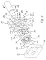
- FIG 2 is a perspective exploded view of one preferred implementation of the encoder 17 of Figure 1c.
- a stator 19 is configured as a dual-in-line package with six terminals 21 to 26.
- the terminals 21-25 correspond to the output terminals A'-E' of Figure 1c, and the terminal 26 corresponds to the ground connection 18.
- the terminals 21-25 are conductively connected to respective arc-shaped pick-up segments 21a-25a.
- the terminal 26 is conductively connected to a collector ring 26a.
- Each terminal 21-25 and respective pick-up segment 21a-25a are formed as a single, metallic piece that is mounted to and partially housed within a substrate portion 20 of the stator 19.
- the terminal 26 and collector ring 26a may be formed in a similar manner.
- the pick-up segments 21a-25a and the collector ring 26a may be formed as lanes on the substrate 20, and then conductively connected to the respective terminals 21-26 by solder.
- the pull-up resistors 16 ( Figure 1c) connected to the output terminals A'-E' are separate from and external to the dual-in-line package, and are therefore not shown in Figure 2.
- a metallic rotor 27 (corresponding to the rotor 8 of Figure 1c) and a detent element 29 are rotated by a shaft 28.
- the shaft 28 has a flat 28a on one side that cooperates with non-circular openings in the rotor 27 and the detent element 29 in order to prevent relative rotation of these parts.
- the rotor 27 comprises four wipers 36, each wiper having a point contact 37 at its end.
- the point contacts 36 are aligned with a single circular track that coincides with the positions of the pick-up segments 21a-25a.
- the point contacts 37 protrude axially in the direction of the stator 19, and contact the pick-up segments 21a-25a as the shaft 28 is rotated.
- the rotor 27 also has ground contacts 38 (shown as point contacts in Figure 2) for contacting the collector ring 26a.
- ground contacts 38 shown as point contacts in Figure 2
- the use of resilient, spring-like wipers 36 assists in maintaining continuous contact between the point contacts 36 and the stator 19.
- wipers is not essential, and other conventional means for urging the point contacts 37 against the stator 19 may be employed.
- one or more additional, “redundant" point contacts may be provided for each point contact 37 shown in Figure 2 (with each redundant point contact positioned on along the same radial line as the corresponding point contact 37).
- the rotor 27 interlocks with a feature 30 (shown in dashed lines) provided on the side of the detent element 29 that faces the rotor 27.
- the detent element 29 On the side opposite from the rotor 27, the detent element 29 has a circumferential band of thirty radially extending serrations 31.
- Detent action is achieved by an annular spring 32 which has a bent detent portion 37 that is resiliently urged by the spring 32 into slidable engagement with the band of serrations 31, in order to define thirty preferred angular positions of the detent element 29, rotor 27, and shaft 28.
- the resilient force exerted by the spring 32 on the detent element 29 is passed on to the rotor 27 in order to urge the rotor 27 against the stator 19.
- a lid 34 closes the device.
- the lid 34 has on the side facing the stator 19 a cylindrical opening 35 (shown in dashed lines) which accommodates the various rotating elements.
- Two recesses project radially outward from diametrically opposite sides of the cylindrical opening 35, and receive respective tabs 33 provided on the annular spring 32 in order to secure the spring 32.
- a conventional stop part could be added to restrict the rotation of the shaft 28 and associated parts to a range of less than 360°.
- the single track encoder according to the present invention can be housed in a sub-miniature package with a large center hole, while yielding satisfactory resolution.
- the ability to manufacture the encoder 17 in a small package is due in-part to the fact that only one track is employed, unlike many prior art encoders which employ multiple concentric tracks. A reduction in size is also made possible by the movement of the wipers to the rotor.
- the encoder 17 can be used to perform such an ON/OFF function (in addition to serving as a general purpose control device) without the need for a dedicated switch structure.
- the chosen "zero" position for the encoder 17 corresponds to the code word "01111.”
- a mechanical stop can establish this zero position as the fully counterclockwise or "OFF" position.
- a decode circuit can then be used to turn off power to the subject electronics when this output value is present.
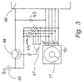
- Figure 3 shows a circuit that performs such a function.
- the circuit includes a 4-input AND gate 47 having its respective inputs connected to output terminals A', B', C' and D' of the encoder 17.
- the output of the AND gate 47 is connected to the base of a PNP switching transistor 48, which serves as a switch through which current passes from a DC power source 49 to radio electronics 46.
- the DC power source 49 is also connected to the outputs A'-D' of the encoder 17 via respective pull-up resistors 44.
- the output E' of the encoder 17 is connected to the collector of the transistor 45 via a pull-up resistor 45.
- the output of the encoder 17 on the lines A'-D' is any value other than "1111,” the output of the AND gate 47 is low, maintaining the transistor 48 in an ON state and allowing current to flow to the radio electronics 46.
- the encoder shaft is in one of the twenty-nine discrete positions other than the zero position, power is provided to the radio electronics 46. These non-zero positions may be used, for example, to define twenty-nine discrete volume settings for the radio.
- the output of the encoder 17 on the lines A'-D' is "1111,” (when the encoder shaft is in the zero position), the transistor 48 turns off, effectively disconnecting the electronics 46 from the power source 49.
- a five-input AND gate can be used to detect this code, and to generate a "SEND” or "ENTER” command.
- the spring 32 Upon release of the shaft 28, the spring 32 returns the rotor 27 to its original axial position, and the angular-position-based output code is reinstated.
- the Gray coded output sequence of the encoder 17 is built into the relative angular positions of the wipers 8a-8d ( Figure 1c), and into the arrangement of the pick-up segments 11-15 along the pick-up track.
- the pick-up segments are symmetrically spaced around the pick-up track, with each segment 11-15 having a length corresponding to four discrete encoder positions.
- This symmetric arrangement of pick-up segments produces a cyclical output, wherein the sequence of states seen at one output terminal during one cycle repeats on the next output terminal during the next cycle.
- This characteristic of the output sequence is best seen in Figure 1b, in which reference characters 40 and 41 denote separate six-position cycles of the encoder 17.
- each block of five output codes (such as the block 41) is identical to the previous block, except that the rows are rotated downward by one position.
- the rows "000011”, “111000”, “110000”, “100001” and “111111” respectively correspond to contacts E, D, C, B and A at 40, and respectively correspond to contacts D, C, B, A and E at 41, and so forth.
- the output sequence repeats itself after every six positions, but with the output terminals A-E rotated by one position.
- the output code "01111” at position 0 and the output code "00111” at position 29 differ in only one digit.
- the output is thus a cyclic Gray code sequence.
- Figure 4a represents the output code sequence for sixteen consecutive positions 0-F (or one cycle) of an encoder which is similar to the encoder 17 of Figures 1c and 2, but which has 128 angular positions and produces an 8-bit binary output on contacts A-H.
- the sequence is tabulated as 8 rows of 16 cells, with black cells representing contacts to ground. The rows represent the states that each of eight contacts A through H sees when stepping through 16 of the 128 angular positions or increments.
- the sequence of 16 output codes illustrated in Figure 4a will repeat itself with each successive cycle (for a total of eight cycles), with the output terminals A to H rotated upward by one place with each successive cycle.
- the entire sequence of 128 8-bit output codes is fully specified by the code sequence shown in Figure 4a.
- FIG. 4a shows the properties of the code sequence of Figure 4a, it is first necessary to verify that all 128 code bytes are different. This is done by resorting to a mathematical concept known as the necklace.
- a necklace represents one candidate of all the elements (in this case 8-bit codes) which are cyclic permutations of each other.
- a good description and an algorithm to generate the necklaces is found in: Frank Ruskey, "Generating Necklaces", Journal of Algorithms, Vol.13, pp. 414-430, 1992. Since the present arrangement will rotate through all of the cyclic permutations, it is important to be sure the present code is made from sixteen different necklaces.
- the 128-code sequence represented by Figure 4a is a Gray code sequence, as exactly one output bit differs between adjacent code words (including code words 127 and 0).
- Figure 4c shows an encoder 50 which is a physical implementation of the code table of Figure 4a.
- the conductive pick-up segments 51 in this case are provided directly on a circuit board 52, and are arranged completely symmetrically around the single pick-up track.
- Each pick-up segment has a length that corresponds to eight rotor positions, since the horizontal bands of black cells in Figure 4a are each eight cells wide (as further described below).
- the angular information comes about by means of the relative angular locations of the respective point contacts on the wipers 53.
- the relative angular locations of the point contacts correspond to the relative positions of the eight white-to-black transitions in Figure 4a.
- the knob 54 and shaft 55 are supported on the circuit board 52 by a bushing 56. Ground is picked up from the ring 58 by the wiper 57.
- the entire 128 position sequence comprises equal length bands of black cells that are separated by varying numbers of white cells. Since all of the bands of black cells are of equal length, a total of eight point contacts (corresponding to the number of equal-length bands in Figure 4a) must be provided along the pick-up track (as shown in Figure 4c). If one or more bands of black cells had a different length, a greater number of point contacts would be required on the rotor. Thus, the solution illustrated by Figures 4a4c is an "optimal" solution, in that the number of wipers on the rotor is minimized.
- the 30-position encoder 17 of Figure 1c is an example of a non-optimum solution.
- the output sequence features two bands of 4 black cells (i.e., bands of zeros) and one band of 7 cells, with the 7-cell band corresponding to two 4-cell bands that overlap by one position. Since all bands do not have the same length, the minimum number of three wipers must be exceeded. Specifically, a fourth wiper (8c or 8d) must be provided in order to obtain sequences of seven consecutive zeros. Note in Figure 1c that since the wipers 8c and 8d are disposed three cells apart, a given pick-up segment will be grounded for seven consecutive positions as the wipers 8c and 8d pass over that segment. Incidentally, the four wipers 8a-8d of Figure 1c are still less than the five wipers 1-5 utilized by the encoder 16 of Figure 1a.
- a suitable output sequence (such as the sequences of Figures 1c and 4a) must be generated in order to design an encoder of the type shown in Figures 1c and 4c.
- Such an output sequence will preferably be a cyclic Gray code sequence having a unique code for each encoder position. Further, where possible, all bands of zeros in the sequence should be of equal length.
- suitable sequences must presently be generated solely by combinatorial trial and error.
- the total number of increments for a full 360° revolution must be a multiple of the number of output bits.
- the encoder 17 has 30 positions (a multiple of five), and the encoder shown in Figure 4c has 128 positions (a multiple of 8). This condition restricts the selection of possible code-lengths.
- the number of positions or increments is not critical. In other cases, it might be desirable to divide 360° into a specific number of steps; a decimal or a power of two being preferred choices.
- Figure 5 illustrates a 32 position encoder 60 based on a ternary code (i.e., a code wherein each digit can take on one of three states).
- a ternary code i.e., a code wherein each digit can take on one of three states.
- Four wipers 65 and 66 are provided on the rotor in a manner similar to the binary case (Figure 1c), except that in Figure 5 the wipers 65 and 66 are connected to two conductive rings 67 and 68 respectively.
- the rings 67 and 68 are connected to ground and to the supply voltage Vcc, respectively, and are fixed to one another (in electric isolation) so that all of the wipers rotate in unison.
- the voltage levels of ground and V cc define two of the three states for each output line.
- the third state is the "open" state, which exists for a given pick-up segment 61-64 when none of the
- FIG. 6 shows a 300 position linear encoder 70 which has a travel distance of 120mm and a total length of 140mm, and which is thus comparable in size to a conventional resistive fader.
- a metallic wiper assembly 71 (or “slider") slidably engages a "common” or ground bus 73 through contacts 72, which serves to maintain the entire wiper assembly 71 at ground.
- the linear encoder has two sides, 74 and 75, the side 74 featuring a length "30" sequence, and the side 75 featuring a length "25" sequence.
- the eight wipers on the wiper assembly 72 are divided into two groups of four, one group corresponding to the side 74, and the other group corresponding to the side 75.
- One such group is shown by reference number 79.
- Five bus lines 77, 78 are provided on each side 74, 75 respectively, with each line being connected to every fifth contact plate.
- the contact plate 80 for example, is connected to the uppermost bus line shown in Figure 6.
- the bus lines 77 and 78 are connected to output terminals (not shown) of the encoder 70.
- the distribution of contact plates on the modulo-30 side 74 is the now familiar one - a contact plate four increments wide and then a gap of two increments (comparable to the length and spacing of the pick-up segments 11-15 in Figure 1c).
- each contact plate is three increments wide, and the gap between adjacent contact plates is two segments wide.
- the smallest common multiple of "25" and "30" is "150". This number can be doubled by offsetting the two tracks (or the wipers on either side) by one increment.
- the scale 76 shows the division thus obtained (from 0 to 299), at which point the pattern repeats.
Landscapes
- Physics & Mathematics (AREA)
- General Physics & Mathematics (AREA)
- Engineering & Computer Science (AREA)
- Theoretical Computer Science (AREA)
- Transmission And Conversion Of Sensor Element Output (AREA)
- Input Circuits Of Receivers And Coupling Of Receivers And Audio Equipment (AREA)
- Selective Calling Equipment (AREA)
- Control Of Electric Motors In General (AREA)
Abstract
Description
Claims (22)
- An absolute Gray code digital position encoder (17; 50; 60; 70), comprising:wherein no more than one digit of said output code changes at a time when said movable member is moved relative to said plurality of pick-up segments, so that a resulting sequence of values of said output code is a Gray code sequence.a plurality of conductive pick-up segments (21a-25a; 51; 61-64; 79) positioned along a common pick-up track, each pick-up segment corresponding to a respective digit of an output code;a moveable member (8, 27) which is movable relative to said plurality of pick-up segments; anda plurality of contacts (37; 53; 65; 71) electrically connected to one another such that said plurality of contacts are at a common voltage, each of said plurality of contacts being positioned in alignment with said common pick-up track and moveable into and out of contact with at least two of said pick-up segments in response to movement of said movable member relative to said pick-up segments, said plurality of contacts being moveable with respect to said pick-up segments to define N discrete encoder settings, each discrete encoder setting producing a unique value of said output code;
- The absolute digital position encoder according to Claim 1, wherein said plurality of contacts (37; 53) are provided on a metallic rotor (27; 67), and wherein said contacts move into and out of sliding contact with said pick-up segments (21a - 25a; 51; 61 - 64) to modify said output code when said rotor is rotated relative to said pick-up segments.
- The absolute digital position encoder according to Claim 1 or 2, wherein said pick-up segments (51) comprise respective pads on a printed circuit board (52).
- The absolute digital position encoder according to any of Claims 1 to 3, wherein each of said contacts moves into and out of operable contact with each of said pick-up segments.
- The absolute digital position encoder according to any of Claims 1 to 4, wherein the value of said output code at each of said discrete settings differs in only one digit relative to the value of said output code at discrete encoder settings immediately adjacent thereto.
- The absolute digital position encoder according to any of Claims 1 to 5, wherein said contacts are provided on a rotary member which is rotatable relative to said pick-up track.
- The absolute digital position encoder according to Claim 6, wherein said rotary member is rotatable relative to said pick-up track over an operable range which exceeds 90°.
- The absolute digital position encoder according to Claim 6 or 7, wherein said rotary member is rotatable relative to said pick-up track over an operable range of at least 270°.
- The absolute digital position encoder according to Claim 6 or 8, wherein said rotary member is rotatable continuously relative to said pick-up track, and wherein said output code follows a Gray code sequence through multiple revolutions of said rotary member relative to said pick-up track.
- The absolute digital position encoder according to any of Claims 1 to 9, wherein a sequence of values of said output code corresponding to said N settings is a cyclic Gray code sequence.
- The absolute digital position encoder according to any of Claims 1 to 10, wherein the number of unique output code values in said cyclic Gray code sequence is at least 30.
- The absolute digital position encoder according to any of Claims 1 to 11, wherein said contacts are provided on a rotor which is coupled to a shaft (28; 55).
- The absolute digital position encoder according to Claim 12, wherein said shaft is connected to said rotor such that at least a portion of said rotor is moved away from said pick-up track when an axial force is applied to said shaft to thereby generate a unique output code value which does not correspond to any of said N settings.
- The absolute digital position encoder according to any of Claims 1 to 13, wherein each of said pick-up segments is contiguous along said pick-up track.
- The absolute digital position encoder according to any preceding Claim, wherein each of said digits is a binary digit.
- The absolute digital position encoder according to Claim 1, further comprising a second plurality of contacts (66) that are connected together and maintained at a second voltage (Vcc) which is different from the common voltage (GND), each of the second plurality of contacts positioned along the pick-up track and movable into and out of contact with the pick-up segments.
- The absolute digital position encoder according to any preceding Claim, wherein each of said digits is a ternary digit.
- A method of generating a code word that represents the relative position of first and second members, the first and second members being supported for relative movement, the method comprising the steps of:providing a plurality of pick-up segments (21a-25a; 51; 61-64; 79) on the first member along a pick-up track, each of the pick-up segments corresponding to a respective digit of the code word;providing a plurality of contacts (37; 53; 65; 71) on the second member such that each of said contacts moves into and out of contact with at least two of said pick-up segments during said relative movement of the first and second members;maintaining said plurality of contacts at a common voltage during said relative movement to modify voltage states of said pick-up segments; andsensing the voltage states of the pick-up segments to generate said code word, wherein each value of said code word corresponds uniquely to a relative position of the first and second members, and a sequence of said values generated by relative movement of said first and second members is a Gray code sequence.
- The method as in Claim 18, wherein the step of providing a plurality of pick-up segments on the first member comprises forming metallic pads on a circuit board (52), each of the metallic pads forming a contiguous pick-up segment along the pick-up track.
- The method according to Claim 18 or 19, wherein the plurality of contacts are provided on a metallic rotor (27; 67), and the step of maintaining comprises applying the common voltage to the rotor.
- The method according to any of Claims 18 to 20, wherein the step of providing the plurality of contacts on the second member comprises positioning said contacts such that only one of said contacts moves into or out of contact with any one of said pick-up segments at-a-time during said relative movement.
- The method according to any of Claims 18 to 21, further comprising the steps of:providing a second plurality of contacts on the second member such that each of said second plurality of contacts moves into and out of contact with said pick-up segments; andmaintaining said second plurality of contacts at a second voltage (Vcc) during said relative movement, said second voltage being different from said common voltage (GND), such that each pick-up segment transitions between at least three voltage states during said relative movement to produce a code word having an order of at least three.
Applications Claiming Priority (3)
| Application Number | Priority Date | Filing Date | Title |
|---|---|---|---|
| US08/359,703 US5739775A (en) | 1993-07-22 | 1994-12-20 | Digital input and control device |
| US359703 | 1994-12-20 | ||
| PCT/US1995/016972 WO1996019872A1 (en) | 1994-12-20 | 1995-12-19 | Digital input and control device |
Publications (2)
| Publication Number | Publication Date |
|---|---|
| EP0800725A1 EP0800725A1 (en) | 1997-10-15 |
| EP0800725B1 true EP0800725B1 (en) | 1999-09-01 |
Family
ID=23414936
Family Applications (1)
| Application Number | Title | Priority Date | Filing Date |
|---|---|---|---|
| EP95944421A Expired - Lifetime EP0800725B1 (en) | 1994-12-20 | 1995-12-19 | Digital input and control device |
Country Status (9)
| Country | Link |
|---|---|
| US (2) | US5739775A (en) |
| EP (1) | EP0800725B1 (en) |
| JP (1) | JPH10511183A (en) |
| AT (1) | ATE184138T1 (en) |
| AU (1) | AU4647396A (en) |
| CA (1) | CA2208325A1 (en) |
| DE (1) | DE69511894D1 (en) |
| MX (1) | MX9704598A (en) |
| WO (1) | WO1996019872A1 (en) |
Cited By (3)
| Publication number | Priority date | Publication date | Assignee | Title |
|---|---|---|---|---|
| DE10392297B4 (en) * | 2002-03-01 | 2007-04-05 | Cooper Cameron Corp., Houston | Method for determining the position of a moving object relative to a stationary object using bit patterns, with a sample bit pattern signal that directly indicates object position and direction of movement without signal summation |
| WO2010049046A1 (en) * | 2008-10-30 | 2010-05-06 | Dr. Johannes Heidenhain Gmbh | Absolute position measuring device |
| WO2010049049A1 (en) * | 2008-10-30 | 2010-05-06 | Dr Johannes Heidenhain Gmbh | Absolute position measuring device |
Families Citing this family (66)
| Publication number | Priority date | Publication date | Assignee | Title |
|---|---|---|---|---|
| JP3170449B2 (en) * | 1996-03-25 | 2001-05-28 | オークマ株式会社 | Absolute encoder |
| FR2757628B1 (en) * | 1996-12-20 | 1999-02-26 | Eaton Controls | METHOD AND DEVICE FOR DIGITAL MEASUREMENT OF ANGULAR POSITIONS |
| US5841274A (en) * | 1997-01-29 | 1998-11-24 | Mitutoyo Corporation | Induced current absolute position transducer using a code-track-type scale and read head |
| US7469381B2 (en) | 2007-01-07 | 2008-12-23 | Apple Inc. | List scrolling and document translation, scaling, and rotation on a touch-screen display |
| US20030160711A1 (en) * | 2000-03-21 | 2003-08-28 | Jorgensen Martin Bondo | Potentiometer assembly providing an encoded output signal |
| US6462677B1 (en) * | 2000-05-09 | 2002-10-08 | Bourns, Inc. | Encoder with embedded signal circuitry |
| US6424928B1 (en) | 2000-06-15 | 2002-07-23 | Eim Company, Inc. | Absolute position detector interpreting abnormal states |
| US6577985B2 (en) | 2000-12-07 | 2003-06-10 | Eim Company, Inc. | Scalable code absolute logic function (SCALF) encoder |
| US20020125113A1 (en) * | 2001-03-06 | 2002-09-12 | Mayur Bhakta | Contacting incremental encoder |
| DE10241868A1 (en) * | 2001-09-11 | 2003-03-27 | Marquardt Gmbh | Direct digital control switch for motorized power tool, encodes discrete trigger positions for transmission to controller determining motor operation |
| DE10201496A1 (en) * | 2002-01-17 | 2003-07-31 | Heidenhain Gmbh Dr Johannes | Scale and position measuring device for absolute position determination |
| JP2004095242A (en) * | 2002-08-30 | 2004-03-25 | Tsubame Musen Kk | Rotary encoder and manufacturing method for substrate of the same |
| US6927351B2 (en) * | 2003-05-16 | 2005-08-09 | Whirlpool Corporation | Rotary switch |
| US6740833B1 (en) * | 2003-05-23 | 2004-05-25 | Defond Components Limited | Electrical switch |
| CN1328575C (en) * | 2003-07-31 | 2007-07-25 | 阿尔卑斯电气株式会社 | Absolute angle detection device |
| FR2865274B1 (en) * | 2004-01-21 | 2006-04-28 | Valeo Climatisation | ROTARY RELAY ENCODER, AND CONTROL PANEL OF A MOTOR VEHICLE PROVIDED WITH SUCH AN ENCODER. |
| TWI290272B (en) * | 2004-03-12 | 2007-11-21 | Murata Machinery Ltd | Moving body system |
| JP4496154B2 (en) * | 2005-10-31 | 2010-07-07 | 株式会社リコー | Rotary encoder, roller member, belt conveying device, image forming device |
| KR100701182B1 (en) | 2006-04-27 | 2007-03-28 | 주식회사 대우일렉트로닉스 | Encoder switch output signal recognition method |
| IL183471A0 (en) | 2007-05-28 | 2007-09-20 | Yaskawa Europ Technology Ltd | Absolute encoder |
| DE102008053985A1 (en) * | 2008-10-30 | 2010-05-06 | Dr. Johannes Heidenhain Gmbh | Absolute angle coding and angle measuring device |
| DE102008054042A1 (en) * | 2008-10-30 | 2010-05-06 | Dr. Johannes Heidenhain Gmbh | Absolute position coding and position measuring device |
| CN101728110A (en) * | 2008-10-30 | 2010-06-09 | 鸿富锦精密工业(深圳)有限公司 | Rotary switch and angle detection device provided with same |
| DE102010001967A1 (en) * | 2010-02-16 | 2011-08-18 | Robert Bosch GmbH, 70469 | Operating element for hand tool machine |
| US12300449B2 (en) | 2012-10-26 | 2025-05-13 | Lutron Technology Company Llc | Battery-powered retrofit remote control device |
| US9538619B2 (en) | 2012-10-26 | 2017-01-03 | Lutron Electronics Co., Inc. | Controllable light source |
| US9212935B2 (en) * | 2012-10-30 | 2015-12-15 | Panasonic Intellectual Property Management Co., Ltd. | Rotary encoder |
| US10691230B2 (en) | 2012-12-29 | 2020-06-23 | Apple Inc. | Crown input for a wearable electronic device |
| US10275117B2 (en) | 2012-12-29 | 2019-04-30 | Apple Inc. | User interface object manipulations in a user interface |
| US10201664B2 (en) | 2013-02-19 | 2019-02-12 | Novo Nordisk A/S | Dose capturing cartridge module for drug delivery device |
| WO2014128156A1 (en) * | 2013-02-19 | 2014-08-28 | Novo Nordisk A/S | Rotary sensor module with axial switch |
| JP2016506845A (en) | 2013-02-19 | 2016-03-07 | ノボ・ノルデイスク・エー/エス | Drug delivery device with dose capture module |
| US10503388B2 (en) | 2013-09-03 | 2019-12-10 | Apple Inc. | Crown input for a wearable electronic device |
| US11068128B2 (en) | 2013-09-03 | 2021-07-20 | Apple Inc. | User interface object manipulations in a user interface |
| US10001817B2 (en) | 2013-09-03 | 2018-06-19 | Apple Inc. | User interface for manipulating user interface objects with magnetic properties |
| KR20210008944A (en) | 2013-09-03 | 2021-01-25 | 애플 인크. | User interface for manipulating user interface objects with magnetic properties |
| US10545657B2 (en) | 2013-09-03 | 2020-01-28 | Apple Inc. | User interface for manipulating user interface objects |
| US12287962B2 (en) | 2013-09-03 | 2025-04-29 | Apple Inc. | User interface for manipulating user interface objects |
| US9649448B2 (en) | 2013-11-21 | 2017-05-16 | Novo Nordisk A/S | Rotary sensor module with resynchronization feature |
| CN105764550B (en) * | 2013-11-21 | 2019-12-24 | 诺和诺德股份有限公司 | Rotary Sensor Assembly with Axial Switch and Redundancy Features |
| CN105722540B (en) * | 2013-11-21 | 2019-06-28 | 诺和诺德股份有限公司 | Rotary sensor assembly with space efficient design |
| EP2884239B1 (en) * | 2013-12-13 | 2016-09-28 | The Swatch Group Research and Development Ltd. | Angular and axial position sensor arrangement |
| JP2015216080A (en) * | 2014-05-13 | 2015-12-03 | アルプス電気株式会社 | Multipoint switching device |
| US9633557B2 (en) | 2014-06-24 | 2017-04-25 | Lutron Electronics Co., Inc. | Battery-powered retrofit remote control device |
| CN110825299B (en) | 2014-06-27 | 2024-03-29 | 苹果公司 | Reduced size user interface |
| TWI676127B (en) | 2014-09-02 | 2019-11-01 | 美商蘋果公司 | Method, system, electronic device and computer-readable storage medium regarding electronic mail user interface |
| WO2016036416A1 (en) | 2014-09-02 | 2016-03-10 | Apple Inc. | Button functionality |
| CN106797493A (en) | 2014-09-02 | 2017-05-31 | 苹果公司 | Music user interface |
| US20160062571A1 (en) | 2014-09-02 | 2016-03-03 | Apple Inc. | Reduced size user interface |
| US10365807B2 (en) | 2015-03-02 | 2019-07-30 | Apple Inc. | Control of system zoom magnification using a rotatable input mechanism |
| JP6907212B2 (en) * | 2015-12-28 | 2021-07-21 | ノボ・ノルデイスク・エー/エス | Rotary sensor assembly with low power features |
| EP3432949B1 (en) | 2016-03-25 | 2024-05-01 | Eli Lilly and Company | Determination of a dose set and delivered in a medication delivery device |
| US11266788B2 (en) | 2016-04-19 | 2022-03-08 | Eli Lilly And Company | Determination of a dose in a medication delivery device using two moving arrays with teeth and a sensor |
| AU2017297299C1 (en) | 2016-07-15 | 2020-06-11 | Eli Lilly And Company | Dose detection module for a medication delivery device |
| US9636464B1 (en) * | 2016-08-01 | 2017-05-02 | Innovative Precision Instruments Limited | Drug delivery device and a drug information detection device |
| WO2018031390A1 (en) | 2016-08-12 | 2018-02-15 | Eli Lilly And Company | Dose sensing mechanism in a medication delivery device |
| CA3046804C (en) | 2016-12-15 | 2022-07-19 | Eli Lilly And Company | Medication delivery device with sensing system |
| CA3073512C (en) | 2017-08-21 | 2023-04-25 | Eli Lilly And Company | Dose detection module for a medication delivery device |
| EP4667032A3 (en) | 2017-08-21 | 2026-02-25 | Eli Lilly and Company | Medication delivery device with sensing system |
| WO2019113673A1 (en) * | 2017-12-12 | 2019-06-20 | Raytheon Canada Ltd. | Rotary switch or other encoder having non-sequential unique bit pattern and method for design |
| CN112566681B (en) | 2018-08-17 | 2022-11-08 | 伊莱利利公司 | Dose detection system for a drug delivery device |
| US10712824B2 (en) | 2018-09-11 | 2020-07-14 | Apple Inc. | Content-based tactile outputs |
| US11435830B2 (en) | 2018-09-11 | 2022-09-06 | Apple Inc. | Content-based tactile outputs |
| US12397119B2 (en) | 2019-02-27 | 2025-08-26 | Eli Lilly And Company | Medication delivery device with sensing system |
| CN118534710A (en) * | 2023-02-21 | 2024-08-23 | 中强光电股份有限公司 | Lens module, projection device and method for adjusting lens module |
| US12567415B2 (en) | 2023-05-09 | 2026-03-03 | Apple Inc. | Providing and controlling immersive three-dimensional environments |
Family Cites Families (27)
| Publication number | Priority date | Publication date | Assignee | Title |
|---|---|---|---|---|
| US3048669A (en) * | 1959-07-15 | 1962-08-07 | Gen Motors Corp | Electrical apparatus |
| FR1445739A (en) * | 1965-06-04 | 1966-07-15 | Alcatel Sa | Digital coding process and its applications |
| US3835377A (en) * | 1970-03-09 | 1974-09-10 | Kogyo Gijutsuin | Three terminal magnetoresistive magnetic field detector in which voltages of opposite polarity relative to ground are applied to opposite ends |
| US3659083A (en) * | 1970-09-03 | 1972-04-25 | Cutler Hammer Inc | Binary coded readout device |
| US4109207A (en) * | 1976-10-27 | 1978-08-22 | S. P. Radio A/S | Coding member for programming of a radio communication apparatus |
| JPS622271Y2 (en) * | 1979-02-08 | 1987-01-20 | ||
| GB2066602A (en) * | 1979-12-20 | 1981-07-08 | Ferranti Ltd | Absolute position encoder |
| DE3035774A1 (en) * | 1980-09-23 | 1982-05-27 | Robert Bosch Gmbh, 7000 Stuttgart | Digital position transducer - has series of markings on one part generating bit patterns in row of detectors |
| CH648929A5 (en) * | 1982-07-07 | 1985-04-15 | Tesa Sa | CAPACITIVE MOVEMENT MEASURING DEVICE. |
| JPS5980186A (en) * | 1982-10-26 | 1984-05-09 | Fanuc Ltd | Rotor position detecting circuit for motor |
| JPS62235504A (en) * | 1986-04-04 | 1987-10-15 | Mitsutoyo Corp | Capacity-type position measuring transducer |
| GB2202677B (en) * | 1987-03-23 | 1990-10-03 | British Gas Plc | Encoder |
| JPS63172903U (en) * | 1987-05-01 | 1988-11-10 | ||
| GB2211040B (en) * | 1987-10-12 | 1991-06-05 | British Gas Plc | Encoder |
| JPH01201613A (en) * | 1988-02-05 | 1989-08-14 | Olympus Optical Co Ltd | Encoder device |
| US4901072A (en) * | 1988-02-17 | 1990-02-13 | Westinghouse Electric Corp. | Position detector utilizing gray code format |
| US4947166A (en) * | 1988-02-22 | 1990-08-07 | Dynamics Research Corporation | Single track absolute encoder |
| US4906992A (en) * | 1988-02-22 | 1990-03-06 | Dynamics Research Corporation | Single track absolute encoder |
| FR2638918B1 (en) * | 1988-11-04 | 1993-04-30 | Merlin Gerin | ENCODER WHEEL |
| GB8826114D0 (en) * | 1988-11-08 | 1988-12-14 | The Technology Partnership Ltd | Decoding of random sequences |
| CA2003143C (en) * | 1988-12-28 | 1998-10-20 | Robert J. Tolmie, Jr. | Sensor with absolute digital output |
| WO1991000984A1 (en) * | 1989-07-07 | 1991-01-24 | Kabushiki Kaisha Yaskawa Denki Seisakusho | Absolute value encoder |
| JPH0742096Y2 (en) * | 1990-10-26 | 1995-09-27 | 株式会社ニコン | Encoder |
| WO1993021499A1 (en) * | 1992-04-22 | 1993-10-28 | Copal Company Limited | Absolute encoder |
| US5315077A (en) * | 1993-04-05 | 1994-05-24 | Bourns, Inc. | Rotary switch including cam operated flexible contacts |
| US5519393A (en) * | 1993-07-22 | 1996-05-21 | Bouens, Inc. | Absolute digital position encoder with multiple sensors per track |
| SG52286A1 (en) * | 1993-07-22 | 2001-01-16 | Bourns Inc | Absolute digital position encoder |
-
1994
- 1994-12-20 US US08/359,703 patent/US5739775A/en not_active Expired - Fee Related
-
1995
- 1995-12-19 AU AU46473/96A patent/AU4647396A/en not_active Abandoned
- 1995-12-19 WO PCT/US1995/016972 patent/WO1996019872A1/en not_active Ceased
- 1995-12-19 AT AT95944421T patent/ATE184138T1/en not_active IP Right Cessation
- 1995-12-19 CA CA002208325A patent/CA2208325A1/en not_active Abandoned
- 1995-12-19 JP JP8520044A patent/JPH10511183A/en active Pending
- 1995-12-19 EP EP95944421A patent/EP0800725B1/en not_active Expired - Lifetime
- 1995-12-19 DE DE69511894T patent/DE69511894D1/en not_active Expired - Lifetime
-
1997
- 1997-01-29 US US08/788,453 patent/US5751230A/en not_active Expired - Fee Related
- 1997-06-19 MX MX9704598A patent/MX9704598A/en not_active IP Right Cessation
Cited By (5)
| Publication number | Priority date | Publication date | Assignee | Title |
|---|---|---|---|---|
| DE10392297B4 (en) * | 2002-03-01 | 2007-04-05 | Cooper Cameron Corp., Houston | Method for determining the position of a moving object relative to a stationary object using bit patterns, with a sample bit pattern signal that directly indicates object position and direction of movement without signal summation |
| WO2010049046A1 (en) * | 2008-10-30 | 2010-05-06 | Dr. Johannes Heidenhain Gmbh | Absolute position measuring device |
| WO2010049049A1 (en) * | 2008-10-30 | 2010-05-06 | Dr Johannes Heidenhain Gmbh | Absolute position measuring device |
| CN102203561A (en) * | 2008-10-30 | 2011-09-28 | 约翰尼斯海登海恩博士股份有限公司 | Absolute position measuring device |
| CN102203561B (en) * | 2008-10-30 | 2014-07-16 | 约翰内斯·海德汉博士有限公司 | Absolute position measuring device |
Also Published As
| Publication number | Publication date |
|---|---|
| US5751230A (en) | 1998-05-12 |
| JPH10511183A (en) | 1998-10-27 |
| US5739775A (en) | 1998-04-14 |
| ATE184138T1 (en) | 1999-09-15 |
| CA2208325A1 (en) | 1996-06-27 |
| AU4647396A (en) | 1996-07-10 |
| DE69511894D1 (en) | 1999-10-07 |
| EP0800725A1 (en) | 1997-10-15 |
| MX9704598A (en) | 1998-07-31 |
| WO1996019872A1 (en) | 1996-06-27 |
Similar Documents
| Publication | Publication Date | Title |
|---|---|---|
| EP0800725B1 (en) | Digital input and control device | |
| US5880683A (en) | Absolute digital position encoder | |
| US5519393A (en) | Absolute digital position encoder with multiple sensors per track | |
| WO1996019872B1 (en) | Digital input and control device | |
| US6873233B2 (en) | Combination switch | |
| US5029304A (en) | Sensor with absolute digital output utilizing Hall Effect devices | |
| EP0635700A1 (en) | Absolute digital position encoder | |
| EP0212578A2 (en) | Absolute position detector | |
| CN101534630A (en) | Multiturn rotational sensor | |
| EP0329451A2 (en) | Position detector | |
| US5838222A (en) | Multiturn potentiometer | |
| EP0196050A2 (en) | Resistor and electron device employing the same | |
| US4345240A (en) | Throttle opening sensor | |
| CA2003143C (en) | Sensor with absolute digital output | |
| US3398245A (en) | Printed circuit switch | |
| US4821644A (en) | Method and apparatus for positioning a member | |
| WO1996023198A1 (en) | Absolute digital position encoder | |
| US6292090B1 (en) | Position detecting switch | |
| CN118464077A (en) | Magnetic encoder | |
| CN116527053A (en) | Analog-to-digital conversion circuit | |
| US6429792B1 (en) | Digital displacement encoding system and method | |
| US3935568A (en) | Universal analog-to-digital converter using the same information disc for different output codes | |
| JPH03285113A (en) | 1-track absolute encoder capable of detecting absolute position when electricity is supplied | |
| JPH01258328A (en) | Rotary encorder-contact | |
| US3487460A (en) | Analog to digital encoder |
Legal Events
| Date | Code | Title | Description |
|---|---|---|---|
| PUAI | Public reference made under article 153(3) epc to a published international application that has entered the european phase |
Free format text: ORIGINAL CODE: 0009012 |
|
| 17P | Request for examination filed |
Effective date: 19970717 |
|
| AK | Designated contracting states |
Kind code of ref document: A1 Designated state(s): AT BE CH DE DK ES FR GB GR IE IT LI LU MC NL PT SE |
|
| RAP1 | Party data changed (applicant data changed or rights of an application transferred) |
Owner name: BOURNS INC. |
|
| 17Q | First examination report despatched |
Effective date: 19980114 |
|
| GRAG | Despatch of communication of intention to grant |
Free format text: ORIGINAL CODE: EPIDOS AGRA |
|
| GRAG | Despatch of communication of intention to grant |
Free format text: ORIGINAL CODE: EPIDOS AGRA |
|
| GRAH | Despatch of communication of intention to grant a patent |
Free format text: ORIGINAL CODE: EPIDOS IGRA |
|
| GRAH | Despatch of communication of intention to grant a patent |
Free format text: ORIGINAL CODE: EPIDOS IGRA |
|
| GRAA | (expected) grant |
Free format text: ORIGINAL CODE: 0009210 |
|
| AK | Designated contracting states |
Kind code of ref document: B1 Designated state(s): AT BE CH DE DK ES FR GB GR IE IT LI LU MC NL PT SE |
|
| PG25 | Lapsed in a contracting state [announced via postgrant information from national office to epo] |
Ref country code: SE Free format text: THE PATENT HAS BEEN ANNULLED BY A DECISION OF A NATIONAL AUTHORITY Effective date: 19990901 Ref country code: NL Free format text: LAPSE BECAUSE OF FAILURE TO SUBMIT A TRANSLATION OF THE DESCRIPTION OR TO PAY THE FEE WITHIN THE PRESCRIBED TIME-LIMIT Effective date: 19990901 Ref country code: LI Free format text: LAPSE BECAUSE OF FAILURE TO SUBMIT A TRANSLATION OF THE DESCRIPTION OR TO PAY THE FEE WITHIN THE PRESCRIBED TIME-LIMIT Effective date: 19990901 Ref country code: IT Free format text: LAPSE BECAUSE OF FAILURE TO SUBMIT A TRANSLATION OF THE DESCRIPTION OR TO PAY THE FEE WITHIN THE PRESCRIBED TIME-LIMIT;WARNING: LAPSES OF ITALIAN PATENTS WITH EFFECTIVE DATE BEFORE 2007 MAY HAVE OCCURRED AT ANY TIME BEFORE 2007. THE CORRECT EFFECTIVE DATE MAY BE DIFFERENT FROM THE ONE RECORDED. Effective date: 19990901 Ref country code: GR Free format text: LAPSE BECAUSE OF NON-PAYMENT OF DUE FEES Effective date: 19990901 Ref country code: FR Free format text: LAPSE BECAUSE OF FAILURE TO SUBMIT A TRANSLATION OF THE DESCRIPTION OR TO PAY THE FEE WITHIN THE PRESCRIBED TIME-LIMIT Effective date: 19990901 Ref country code: ES Free format text: THE PATENT HAS BEEN ANNULLED BY A DECISION OF A NATIONAL AUTHORITY Effective date: 19990901 Ref country code: CH Free format text: LAPSE BECAUSE OF FAILURE TO SUBMIT A TRANSLATION OF THE DESCRIPTION OR TO PAY THE FEE WITHIN THE PRESCRIBED TIME-LIMIT Effective date: 19990901 Ref country code: BE Free format text: LAPSE BECAUSE OF FAILURE TO SUBMIT A TRANSLATION OF THE DESCRIPTION OR TO PAY THE FEE WITHIN THE PRESCRIBED TIME-LIMIT Effective date: 19990901 Ref country code: AT Free format text: LAPSE BECAUSE OF FAILURE TO SUBMIT A TRANSLATION OF THE DESCRIPTION OR TO PAY THE FEE WITHIN THE PRESCRIBED TIME-LIMIT Effective date: 19990901 |
|
| REF | Corresponds to: |
Ref document number: 184138 Country of ref document: AT Date of ref document: 19990915 Kind code of ref document: T |
|
| REG | Reference to a national code |
Ref country code: CH Ref legal event code: EP |
|
| REF | Corresponds to: |
Ref document number: 69511894 Country of ref document: DE Date of ref document: 19991007 |
|
| REG | Reference to a national code |
Ref country code: IE Ref legal event code: FG4D |
|
| PG25 | Lapsed in a contracting state [announced via postgrant information from national office to epo] |
Ref country code: DK Free format text: LAPSE BECAUSE OF FAILURE TO SUBMIT A TRANSLATION OF THE DESCRIPTION OR TO PAY THE FEE WITHIN THE PRESCRIBED TIME-LIMIT Effective date: 19991201 |
|
| PG25 | Lapsed in a contracting state [announced via postgrant information from national office to epo] |
Ref country code: PT Free format text: LAPSE BECAUSE OF FAILURE TO SUBMIT A TRANSLATION OF THE DESCRIPTION OR TO PAY THE FEE WITHIN THE PRESCRIBED TIME-LIMIT Effective date: 19991202 Ref country code: DE Free format text: LAPSE BECAUSE OF FAILURE TO SUBMIT A TRANSLATION OF THE DESCRIPTION OR TO PAY THE FEE WITHIN THE PRESCRIBED TIME-LIMIT Effective date: 19991202 |
|
| PG25 | Lapsed in a contracting state [announced via postgrant information from national office to epo] |
Ref country code: LU Free format text: LAPSE BECAUSE OF NON-PAYMENT OF DUE FEES Effective date: 19991219 Ref country code: GB Free format text: LAPSE BECAUSE OF NON-PAYMENT OF DUE FEES Effective date: 19991219 |
|
| EN | Fr: translation not filed | ||
| NLV1 | Nl: lapsed or annulled due to failure to fulfill the requirements of art. 29p and 29m of the patents act | ||
| REG | Reference to a national code |
Ref country code: CH Ref legal event code: PL |
|
| PG25 | Lapsed in a contracting state [announced via postgrant information from national office to epo] |
Ref country code: MC Free format text: LAPSE BECAUSE OF NON-PAYMENT OF DUE FEES Effective date: 20000630 |
|
| PLBE | No opposition filed within time limit |
Free format text: ORIGINAL CODE: 0009261 |
|
| STAA | Information on the status of an ep patent application or granted ep patent |
Free format text: STATUS: NO OPPOSITION FILED WITHIN TIME LIMIT |
|
| GBPC | Gb: european patent ceased through non-payment of renewal fee |
Effective date: 19991219 |
|
| 26N | No opposition filed | ||
| PGFP | Annual fee paid to national office [announced via postgrant information from national office to epo] |
Ref country code: IE Payment date: 20011219 Year of fee payment: 7 |
|
| PG25 | Lapsed in a contracting state [announced via postgrant information from national office to epo] |
Ref country code: IE Free format text: LAPSE BECAUSE OF NON-PAYMENT OF DUE FEES Effective date: 20021219 |
|
| REG | Reference to a national code |
Ref country code: IE Ref legal event code: MM4A |