EP0800873B1 - Procédé et dispositif pour la décontamination des sols - Google Patents
Procédé et dispositif pour la décontamination des sols Download PDFInfo
- Publication number
- EP0800873B1 EP0800873B1 EP97302449A EP97302449A EP0800873B1 EP 0800873 B1 EP0800873 B1 EP 0800873B1 EP 97302449 A EP97302449 A EP 97302449A EP 97302449 A EP97302449 A EP 97302449A EP 0800873 B1 EP0800873 B1 EP 0800873B1
- Authority
- EP
- European Patent Office
- Prior art keywords
- soil
- probe
- microorganism
- process according
- pollutant
- Prior art date
- Legal status (The legal status is an assumption and is not a legal conclusion. Google has not performed a legal analysis and makes no representation as to the accuracy of the status listed.)
- Expired - Lifetime
Links
- 239000002689 soil Substances 0.000 title claims description 149
- 238000000034 method Methods 0.000 title claims description 44
- 238000005067 remediation Methods 0.000 title claims description 42
- 230000008569 process Effects 0.000 title claims description 30
- XSTXAVWGXDQKEL-UHFFFAOYSA-N Trichloroethylene Chemical group ClC=C(Cl)Cl XSTXAVWGXDQKEL-UHFFFAOYSA-N 0.000 claims description 68
- UBOXGVDOUJQMTN-UHFFFAOYSA-N trichloroethylene Natural products ClCC(Cl)Cl UBOXGVDOUJQMTN-UHFFFAOYSA-N 0.000 claims description 67
- 239000000523 sample Substances 0.000 claims description 60
- 244000005700 microbiome Species 0.000 claims description 51
- 239000003344 environmental pollutant Substances 0.000 claims description 45
- 231100000719 pollutant Toxicity 0.000 claims description 45
- 235000015097 nutrients Nutrition 0.000 claims description 19
- 230000000593 degrading effect Effects 0.000 claims description 18
- 239000007789 gas Substances 0.000 claims description 13
- 239000000411 inducer Substances 0.000 claims description 11
- 239000011796 hollow space material Substances 0.000 claims description 8
- 239000002269 analeptic agent Substances 0.000 claims description 7
- 238000011049 filling Methods 0.000 claims description 7
- 230000000813 microbial effect Effects 0.000 claims description 7
- 230000003213 activating effect Effects 0.000 claims description 6
- QVGXLLKOCUKJST-UHFFFAOYSA-N atomic oxygen Chemical compound [O] QVGXLLKOCUKJST-UHFFFAOYSA-N 0.000 claims description 6
- 239000007788 liquid Substances 0.000 claims description 6
- 229910052760 oxygen Inorganic materials 0.000 claims description 6
- 239000001301 oxygen Substances 0.000 claims description 6
- 150000001491 aromatic compounds Chemical class 0.000 claims description 5
- CYTYCFOTNPOANT-UHFFFAOYSA-N Perchloroethylene Chemical group ClC(Cl)=C(Cl)Cl CYTYCFOTNPOANT-UHFFFAOYSA-N 0.000 claims description 3
- 229950011008 tetrachloroethylene Drugs 0.000 claims description 3
- 239000004215 Carbon black (E152) Substances 0.000 claims 2
- 150000007824 aliphatic compounds Chemical class 0.000 claims 2
- 229930195733 hydrocarbon Natural products 0.000 claims 2
- 150000002430 hydrocarbons Chemical class 0.000 claims 2
- 239000000243 solution Substances 0.000 description 25
- 241000894006 Bacteria Species 0.000 description 20
- ISWSIDIOOBJBQZ-UHFFFAOYSA-N Phenol Chemical compound OC1=CC=CC=C1 ISWSIDIOOBJBQZ-UHFFFAOYSA-N 0.000 description 20
- 238000006731 degradation reaction Methods 0.000 description 20
- 230000015556 catabolic process Effects 0.000 description 19
- 238000005259 measurement Methods 0.000 description 17
- FAPWRFPIFSIZLT-UHFFFAOYSA-M Sodium chloride Chemical compound [Na+].[Cl-] FAPWRFPIFSIZLT-UHFFFAOYSA-M 0.000 description 16
- 238000011109 contamination Methods 0.000 description 16
- 239000002609 medium Substances 0.000 description 16
- XLYOFNOQVPJJNP-UHFFFAOYSA-N water Substances O XLYOFNOQVPJJNP-UHFFFAOYSA-N 0.000 description 14
- 238000000605 extraction Methods 0.000 description 12
- 238000002474 experimental method Methods 0.000 description 11
- 229920001817 Agar Polymers 0.000 description 10
- OKTJSMMVPCPJKN-UHFFFAOYSA-N Carbon Chemical compound [C] OKTJSMMVPCPJKN-UHFFFAOYSA-N 0.000 description 10
- 239000004809 Teflon Substances 0.000 description 10
- 229920006362 Teflon® Polymers 0.000 description 10
- 239000008272 agar Substances 0.000 description 10
- 230000003413 degradative effect Effects 0.000 description 10
- 150000004045 organic chlorine compounds Chemical class 0.000 description 10
- 239000003795 chemical substances by application Substances 0.000 description 8
- 230000000052 comparative effect Effects 0.000 description 8
- 238000002347 injection Methods 0.000 description 8
- 239000007924 injection Substances 0.000 description 8
- 239000011780 sodium chloride Substances 0.000 description 8
- 230000000694 effects Effects 0.000 description 7
- 238000010438 heat treatment Methods 0.000 description 7
- 239000000203 mixture Substances 0.000 description 7
- 239000001509 sodium citrate Substances 0.000 description 7
- NLJMYIDDQXHKNR-UHFFFAOYSA-K sodium citrate Chemical compound O.O.[Na+].[Na+].[Na+].[O-]C(=O)CC(O)(CC([O-])=O)C([O-])=O NLJMYIDDQXHKNR-UHFFFAOYSA-K 0.000 description 7
- YXFVVABEGXRONW-UHFFFAOYSA-N Toluene Chemical compound CC1=CC=CC=C1 YXFVVABEGXRONW-UHFFFAOYSA-N 0.000 description 6
- 239000007864 aqueous solution Substances 0.000 description 6
- 230000008859 change Effects 0.000 description 6
- 238000007596 consolidation process Methods 0.000 description 6
- 239000011521 glass Substances 0.000 description 6
- 238000002360 preparation method Methods 0.000 description 6
- 230000001580 bacterial effect Effects 0.000 description 5
- 229920001971 elastomer Polymers 0.000 description 5
- 239000000126 substance Substances 0.000 description 5
- NLXLAEXVIDQMFP-UHFFFAOYSA-N Ammonia chloride Chemical compound [NH4+].[Cl-] NLXLAEXVIDQMFP-UHFFFAOYSA-N 0.000 description 4
- 239000007836 KH2PO4 Substances 0.000 description 4
- 229940041514 candida albicans extract Drugs 0.000 description 4
- 238000010276 construction Methods 0.000 description 4
- 239000000356 contaminant Substances 0.000 description 4
- 238000010790 dilution Methods 0.000 description 4
- 239000012895 dilution Substances 0.000 description 4
- BNIILDVGGAEEIG-UHFFFAOYSA-L disodium hydrogen phosphate Chemical compound [Na+].[Na+].OP([O-])([O-])=O BNIILDVGGAEEIG-UHFFFAOYSA-L 0.000 description 4
- 229910000397 disodium phosphate Inorganic materials 0.000 description 4
- 229910000402 monopotassium phosphate Inorganic materials 0.000 description 4
- GNSKLFRGEWLPPA-UHFFFAOYSA-M potassium dihydrogen phosphate Chemical compound [K+].OP(O)([O-])=O GNSKLFRGEWLPPA-UHFFFAOYSA-M 0.000 description 4
- 239000012138 yeast extract Substances 0.000 description 4
- UHOVQNZJYSORNB-UHFFFAOYSA-N Benzene Chemical compound C1=CC=CC=C1 UHOVQNZJYSORNB-UHFFFAOYSA-N 0.000 description 3
- WQZGKKKJIJFFOK-GASJEMHNSA-N Glucose Natural products OC[C@H]1OC(O)[C@H](O)[C@@H](O)[C@@H]1O WQZGKKKJIJFFOK-GASJEMHNSA-N 0.000 description 3
- 241000589774 Pseudomonas sp. Species 0.000 description 3
- KRKNYBCHXYNGOX-UHFFFAOYSA-N citric acid Chemical compound OC(=O)CC(O)(C(O)=O)CC(O)=O KRKNYBCHXYNGOX-UHFFFAOYSA-N 0.000 description 3
- 238000005516 engineering process Methods 0.000 description 3
- 239000008103 glucose Substances 0.000 description 3
- 239000003673 groundwater Substances 0.000 description 3
- 239000004576 sand Substances 0.000 description 3
- OWEGMIWEEQEYGQ-UHFFFAOYSA-N 100676-05-9 Natural products OC1C(O)C(O)C(CO)OC1OCC1C(O)C(O)C(O)C(OC2C(OC(O)C(O)C2O)CO)O1 OWEGMIWEEQEYGQ-UHFFFAOYSA-N 0.000 description 2
- 229920000936 Agarose Polymers 0.000 description 2
- 241000589513 Burkholderia cepacia Species 0.000 description 2
- FBPFZTCFMRRESA-KVTDHHQDSA-N D-Mannitol Chemical compound OC[C@@H](O)[C@@H](O)[C@H](O)[C@H](O)CO FBPFZTCFMRRESA-KVTDHHQDSA-N 0.000 description 2
- SIKJAQJRHWYJAI-UHFFFAOYSA-N Indole Chemical compound C1=CC=C2NC=CC2=C1 SIKJAQJRHWYJAI-UHFFFAOYSA-N 0.000 description 2
- XEEYBQQBJWHFJM-UHFFFAOYSA-N Iron Chemical compound [Fe] XEEYBQQBJWHFJM-UHFFFAOYSA-N 0.000 description 2
- GUBGYTABKSRVRQ-PICCSMPSSA-N Maltose Natural products O[C@@H]1[C@@H](O)[C@H](O)[C@@H](CO)O[C@@H]1O[C@@H]1[C@@H](CO)OC(O)[C@H](O)[C@H]1O GUBGYTABKSRVRQ-PICCSMPSSA-N 0.000 description 2
- 102000004020 Oxygenases Human genes 0.000 description 2
- 108090000417 Oxygenases Proteins 0.000 description 2
- 241000589776 Pseudomonas putida Species 0.000 description 2
- WNLRTRBMVRJNCN-UHFFFAOYSA-N adipic acid Chemical compound OC(=O)CCCCC(O)=O WNLRTRBMVRJNCN-UHFFFAOYSA-N 0.000 description 2
- 239000003513 alkali Substances 0.000 description 2
- 230000008901 benefit Effects 0.000 description 2
- 238000006065 biodegradation reaction Methods 0.000 description 2
- 239000004927 clay Substances 0.000 description 2
- 150000001875 compounds Chemical class 0.000 description 2
- GHVNFZFCNZKVNT-UHFFFAOYSA-N decanoic acid Chemical compound CCCCCCCCCC(O)=O GHVNFZFCNZKVNT-UHFFFAOYSA-N 0.000 description 2
- 230000003247 decreasing effect Effects 0.000 description 2
- 239000006185 dispersion Substances 0.000 description 2
- 238000001035 drying Methods 0.000 description 2
- 230000002708 enhancing effect Effects 0.000 description 2
- 238000004817 gas chromatography Methods 0.000 description 2
- 230000007062 hydrolysis Effects 0.000 description 2
- 238000006460 hydrolysis reaction Methods 0.000 description 2
- 239000013028 medium composition Substances 0.000 description 2
- VNWKTOKETHGBQD-UHFFFAOYSA-N methane Chemical compound C VNWKTOKETHGBQD-UHFFFAOYSA-N 0.000 description 2
- 230000007483 microbial process Effects 0.000 description 2
- 229920001296 polysiloxane Polymers 0.000 description 2
- 239000008399 tap water Substances 0.000 description 2
- 235000020679 tap water Nutrition 0.000 description 2
- HGUFODBRKLSHSI-UHFFFAOYSA-N 2,3,7,8-tetrachloro-dibenzo-p-dioxin Chemical compound O1C2=CC(Cl)=C(Cl)C=C2OC2=C1C=C(Cl)C(Cl)=C2 HGUFODBRKLSHSI-UHFFFAOYSA-N 0.000 description 1
- 241001453369 Achromobacter denitrificans Species 0.000 description 1
- PLXMOAALOJOTIY-FPTXNFDTSA-N Aesculin Natural products OC[C@@H]1[C@@H](O)[C@H](O)[C@@H](O)[C@H](O)[C@H]1Oc2cc3C=CC(=O)Oc3cc2O PLXMOAALOJOTIY-FPTXNFDTSA-N 0.000 description 1
- 239000004475 Arginine Substances 0.000 description 1
- 102100026189 Beta-galactosidase Human genes 0.000 description 1
- 102100035882 Catalase Human genes 0.000 description 1
- 108010053835 Catalase Proteins 0.000 description 1
- WNBCMONIPIJTSB-BGNCJLHMSA-N Cichoriin Natural products O([C@H]1[C@H](O)[C@@H](O)[C@@H](O)[C@@H](CO)O1)c1c(O)cc2c(OC(=O)C=C2)c1 WNBCMONIPIJTSB-BGNCJLHMSA-N 0.000 description 1
- 241000252867 Cupriavidus metallidurans Species 0.000 description 1
- WQZGKKKJIJFFOK-QTVWNMPRSA-N D-mannopyranose Chemical compound OC[C@H]1OC(O)[C@@H](O)[C@@H](O)[C@@H]1O WQZGKKKJIJFFOK-QTVWNMPRSA-N 0.000 description 1
- 108010010803 Gelatin Proteins 0.000 description 1
- 238000003794 Gram staining Methods 0.000 description 1
- 241000282414 Homo sapiens Species 0.000 description 1
- SRBFZHDQGSBBOR-HWQSCIPKSA-N L-arabinopyranose Chemical compound O[C@H]1COC(O)[C@H](O)[C@H]1O SRBFZHDQGSBBOR-HWQSCIPKSA-N 0.000 description 1
- 241000186783 Lactobacillus vaginalis Species 0.000 description 1
- 241000945786 Methylocystis sp. Species 0.000 description 1
- 241000589342 Methylomonas sp. Species 0.000 description 1
- 241000322541 Methylosinus trichosporium OB3b Species 0.000 description 1
- 241000187644 Mycobacterium vaccae Species 0.000 description 1
- OVRNDRQMDRJTHS-UHFFFAOYSA-N N-acelyl-D-glucosamine Natural products CC(=O)NC1C(O)OC(CO)C(O)C1O OVRNDRQMDRJTHS-UHFFFAOYSA-N 0.000 description 1
- OVRNDRQMDRJTHS-FMDGEEDCSA-N N-acetyl-beta-D-glucosamine Chemical compound CC(=O)N[C@H]1[C@H](O)O[C@H](CO)[C@@H](O)[C@@H]1O OVRNDRQMDRJTHS-FMDGEEDCSA-N 0.000 description 1
- GRYLNZFGIOXLOG-UHFFFAOYSA-N Nitric acid Chemical compound O[N+]([O-])=O GRYLNZFGIOXLOG-UHFFFAOYSA-N 0.000 description 1
- 241000605121 Nitrosomonas europaea Species 0.000 description 1
- CTQNGGLPUBDAKN-UHFFFAOYSA-N O-Xylene Chemical compound CC1=CC=CC=C1C CTQNGGLPUBDAKN-UHFFFAOYSA-N 0.000 description 1
- 102000004316 Oxidoreductases Human genes 0.000 description 1
- 108090000854 Oxidoreductases Proteins 0.000 description 1
- 108091005804 Peptidases Proteins 0.000 description 1
- HLCFGWHYROZGBI-JJKGCWMISA-M Potassium gluconate Chemical compound [K+].OC[C@@H](O)[C@@H](O)[C@H](O)[C@@H](O)C([O-])=O HLCFGWHYROZGBI-JJKGCWMISA-M 0.000 description 1
- 239000004365 Protease Substances 0.000 description 1
- 241000589540 Pseudomonas fluorescens Species 0.000 description 1
- 241000589755 Pseudomonas mendocina Species 0.000 description 1
- 241001041887 Pseudomonas putida F1 Species 0.000 description 1
- MUPFEKGTMRGPLJ-RMMQSMQOSA-N Raffinose Natural products O(C[C@H]1[C@@H](O)[C@H](O)[C@@H](O)[C@@H](O[C@@]2(CO)[C@H](O)[C@@H](O)[C@@H](CO)O2)O1)[C@@H]1[C@H](O)[C@@H](O)[C@@H](O)[C@@H](CO)O1 MUPFEKGTMRGPLJ-RMMQSMQOSA-N 0.000 description 1
- 102100037486 Reverse transcriptase/ribonuclease H Human genes 0.000 description 1
- 229930006000 Sucrose Natural products 0.000 description 1
- CZMRCDWAGMRECN-UGDNZRGBSA-N Sucrose Chemical compound O[C@H]1[C@H](O)[C@@H](CO)O[C@@]1(CO)O[C@@H]1[C@H](O)[C@@H](O)[C@H](O)[C@@H](CO)O1 CZMRCDWAGMRECN-UGDNZRGBSA-N 0.000 description 1
- MUPFEKGTMRGPLJ-UHFFFAOYSA-N UNPD196149 Natural products OC1C(O)C(CO)OC1(CO)OC1C(O)C(O)C(O)C(COC2C(C(O)C(O)C(CO)O2)O)O1 MUPFEKGTMRGPLJ-UHFFFAOYSA-N 0.000 description 1
- 108010046334 Urease Proteins 0.000 description 1
- IPBVNPXQWQGGJP-UHFFFAOYSA-N acetic acid phenyl ester Natural products CC(=O)OC1=CC=CC=C1 IPBVNPXQWQGGJP-UHFFFAOYSA-N 0.000 description 1
- 239000012190 activator Substances 0.000 description 1
- 239000001361 adipic acid Substances 0.000 description 1
- 235000011037 adipic acid Nutrition 0.000 description 1
- 230000002411 adverse Effects 0.000 description 1
- 238000003915 air pollution Methods 0.000 description 1
- 238000004458 analytical method Methods 0.000 description 1
- ODKSFYDXXFIFQN-UHFFFAOYSA-N arginine Natural products OC(=O)C(N)CCCNC(N)=N ODKSFYDXXFIFQN-UHFFFAOYSA-N 0.000 description 1
- 230000000721 bacterilogical effect Effects 0.000 description 1
- 239000000440 bentonite Substances 0.000 description 1
- 229910000278 bentonite Inorganic materials 0.000 description 1
- SVPXDRXYRYOSEX-UHFFFAOYSA-N bentoquatam Chemical compound O.O=[Si]=O.O=[Al]O[Al]=O SVPXDRXYRYOSEX-UHFFFAOYSA-N 0.000 description 1
- SRBFZHDQGSBBOR-UHFFFAOYSA-N beta-D-Pyranose-Lyxose Natural products OC1COC(O)C(O)C1O SRBFZHDQGSBBOR-UHFFFAOYSA-N 0.000 description 1
- 108010005774 beta-Galactosidase Proteins 0.000 description 1
- 102000006995 beta-Glucosidase Human genes 0.000 description 1
- 108010047754 beta-Glucosidase Proteins 0.000 description 1
- 230000000711 cancerogenic effect Effects 0.000 description 1
- 231100000315 carcinogenic Toxicity 0.000 description 1
- 239000011248 coating agent Substances 0.000 description 1
- 238000000576 coating method Methods 0.000 description 1
- 238000001816 cooling Methods 0.000 description 1
- 239000006071 cream Substances 0.000 description 1
- 238000000354 decomposition reaction Methods 0.000 description 1
- 238000001514 detection method Methods 0.000 description 1
- 230000003292 diminished effect Effects 0.000 description 1
- 238000005108 dry cleaning Methods 0.000 description 1
- 230000007613 environmental effect Effects 0.000 description 1
- 238000003912 environmental pollution Methods 0.000 description 1
- XHCADAYNFIFUHF-TVKJYDDYSA-N esculin Chemical compound O[C@@H]1[C@@H](O)[C@H](O)[C@@H](CO)O[C@H]1OC(C(=C1)O)=CC2=C1OC(=O)C=C2 XHCADAYNFIFUHF-TVKJYDDYSA-N 0.000 description 1
- 229940093496 esculin Drugs 0.000 description 1
- AWRMZKLXZLNBBK-UHFFFAOYSA-N esculin Natural products OC1OC(COc2cc3C=CC(=O)Oc3cc2O)C(O)C(O)C1O AWRMZKLXZLNBBK-UHFFFAOYSA-N 0.000 description 1
- 238000000855 fermentation Methods 0.000 description 1
- 230000004151 fermentation Effects 0.000 description 1
- 239000010419 fine particle Substances 0.000 description 1
- 239000000446 fuel Substances 0.000 description 1
- 229930182830 galactose Natural products 0.000 description 1
- 239000008273 gelatin Substances 0.000 description 1
- 229920000159 gelatin Polymers 0.000 description 1
- 235000019322 gelatine Nutrition 0.000 description 1
- 235000011852 gelatine desserts Nutrition 0.000 description 1
- 239000001963 growth medium Substances 0.000 description 1
- PZOUSPYUWWUPPK-UHFFFAOYSA-N indole Natural products CC1=CC=CC2=C1C=CN2 PZOUSPYUWWUPPK-UHFFFAOYSA-N 0.000 description 1
- RKJUIXBNRJVNHR-UHFFFAOYSA-N indolenine Natural products C1=CC=C2CC=NC2=C1 RKJUIXBNRJVNHR-UHFFFAOYSA-N 0.000 description 1
- 229910052742 iron Inorganic materials 0.000 description 1
- 238000002955 isolation Methods 0.000 description 1
- BJEPYKJPYRNKOW-UHFFFAOYSA-N malic acid Chemical compound OC(=O)C(O)CC(O)=O BJEPYKJPYRNKOW-UHFFFAOYSA-N 0.000 description 1
- 235000010355 mannitol Nutrition 0.000 description 1
- 238000004519 manufacturing process Methods 0.000 description 1
- 239000000463 material Substances 0.000 description 1
- 230000004899 motility Effects 0.000 description 1
- 229950006780 n-acetylglucosamine Drugs 0.000 description 1
- 229910017604 nitric acid Inorganic materials 0.000 description 1
- 230000020477 pH reduction Effects 0.000 description 1
- -1 phenol and toluene Chemical class 0.000 description 1
- 229940049953 phenylacetate Drugs 0.000 description 1
- WLJVXDMOQOGPHL-UHFFFAOYSA-N phenylacetic acid Chemical compound OC(=O)CC1=CC=CC=C1 WLJVXDMOQOGPHL-UHFFFAOYSA-N 0.000 description 1
- 239000011148 porous material Substances 0.000 description 1
- 239000004224 potassium gluconate Substances 0.000 description 1
- 229960003189 potassium gluconate Drugs 0.000 description 1
- 235000013926 potassium gluconate Nutrition 0.000 description 1
- 238000012545 processing Methods 0.000 description 1
- 230000035755 proliferation Effects 0.000 description 1
- 238000000746 purification Methods 0.000 description 1
- MUPFEKGTMRGPLJ-ZQSKZDJDSA-N raffinose Chemical compound O[C@H]1[C@H](O)[C@@H](CO)O[C@@]1(CO)O[C@@H]1[C@H](O)[C@@H](O)[C@H](O)[C@@H](CO[C@@H]2[C@@H]([C@@H](O)[C@@H](O)[C@@H](CO)O2)O)O1 MUPFEKGTMRGPLJ-ZQSKZDJDSA-N 0.000 description 1
- 230000009467 reduction Effects 0.000 description 1
- 230000008929 regeneration Effects 0.000 description 1
- 238000011069 regeneration method Methods 0.000 description 1
- 230000000246 remedial effect Effects 0.000 description 1
- 238000012958 reprocessing Methods 0.000 description 1
- 229920005989 resin Polymers 0.000 description 1
- 239000011347 resin Substances 0.000 description 1
- 239000010865 sewage Substances 0.000 description 1
- 244000000000 soil microbiome Species 0.000 description 1
- 239000007787 solid Substances 0.000 description 1
- 238000001179 sorption measurement Methods 0.000 description 1
- 239000005720 sucrose Substances 0.000 description 1
- 231100000378 teratogenic Toxicity 0.000 description 1
- 230000003390 teratogenic effect Effects 0.000 description 1
- 229920002803 thermoplastic polyurethane Polymers 0.000 description 1
- 229920001567 vinyl ester resin Polymers 0.000 description 1
- 238000005406 washing Methods 0.000 description 1
- 239000008096 xylene Substances 0.000 description 1
Images


Classifications
-
- B—PERFORMING OPERATIONS; TRANSPORTING
- B09—DISPOSAL OF SOLID WASTE; RECLAMATION OF CONTAMINATED SOIL
- B09C—RECLAMATION OF CONTAMINATED SOIL
- B09C1/00—Reclamation of contaminated soil
- B09C1/10—Reclamation of contaminated soil microbiologically, biologically or by using enzymes
-
- B—PERFORMING OPERATIONS; TRANSPORTING
- B09—DISPOSAL OF SOLID WASTE; RECLAMATION OF CONTAMINATED SOIL
- B09C—RECLAMATION OF CONTAMINATED SOIL
- B09C2101/00—In situ
Definitions
- the present invention relates to a process for remedying a soil contaminated with a pollutant and an apparatus used therefor.
- Organochlorine compounds such as trichloroethylene and tetrachloroethylene were once extensively used for washing precision parts as well as for dry cleaning, and contamination of soil and underground water on a large scale due to the leakage of the organochlorine compounds are now being revealed. Since such organochlorine chemicals are teratogenic and carcinogenic to adversely affect the biosphere, purification of the polluted soil or ground water is now an issue to be solved immediately in addition to the isolation of the pollution source.
- Methods for remedying soil polluted with these pollutants include, for example, heat treatment of the dug-up soil, vacuum extraction of the contaminant from the polluted soil, and microbial degradation of the pollutant in soil.
- heat treatment can completely purify the soil, the soil must be dug up so that soil under structures cannot be purified.
- it is unsuitable for large-scale treatment because of the immense costs of digging and heating.
- the organochlorine compounds heated and evaporated from the soil which will cause air pollution must be recovered by the adsorption to activated carbon and the like, and then the used activated carbon.
- the vacuum extraction and bioremediation do not require soil dig-up, therefore they are inexpensive and simple processes and can be applied to the soil under the buildings while the ground surface is occupied by the buildings.
- the vacuum extraction process requires the same treatment of the recovered organochlorine compounds as with the heat treatment method.
- compact ground equipment for vacuum extraction was proposed, utilizing a fluidized bed for regeneration of activated carbon to which the abstracted gas has been adsorbed. Ground equipment is still required for the treatment.
- remediation is carried out introducing into the soil activating agents such as nutrients, inducers, oxygen and growth stimulating agents to improve the degradation activity of the native microorganisms.
- strains capable of degrading TCE are given as follows: Welchia alkenophila sero 5 (USP 4877736, ATCC 53570), Welchia alkenophila sero 33 (USP 4877736, ATCC 53571), Methylocystis sp. strain M (Agric. Biol. Chem., 53, 2903 (1989), Biosci. Biotech. Biochem., 56, 486 (1992), ibid. 56, 736 (1992)), Methylosinus trichosporium OB3b (Am. Chem. Soc. Natl. Meet. Dev. Environ. Microbiol., 29, 365 (1989), Appl. Environ.
- remediation is carried out by introducing foreign microorganisms into the soil together with microbial activator for enhancing degradation activity. It is economically desired that microorganisms or chemical substances in an amount as small as possible are introduced and spread into the region to be remedied to carry out the degradation of the pollutants for remediation of the soil. In this sense, the microbial treatment has a drawback since it requires the introduction of a huge amount of a treating solution to remedy a wide region, filling the pore space of the soil to be treated.
- German Patent Application No. DE 4335574 discloses a method for removing contaminants in liquid, solid-liquid and solid water-permeable environments.
- One or more permeable shafts are arranged in the contaminated area, the shafts being filled with a material including microorganisms that decompose or accumulate the contaminant(s).
- the shafts are charged with ground water which issues therefrom carrying microorganisms into the surrounding soil to exert their remedial effect. Thus, there arises secondary contamination of the soil by microorganisms.
- the vacuum extraction process and bioremediation process have advantages over the heat treatment method, yet they still have some problems to be solved for more efficient treatment.
- large-scale equipment may increase the remediation cost
- huge ground equipment may cancel out the advantage of the vacuum extraction process and the bioremediation process over the heat treatment method, that is, the remediation can be carried out maintaining the state of the soil and the ground surface.
- the present invention has been made to solve the above-mentioned problems, and to provide a process for remedying a soil contaminated with a volatile pollutant and an apparatus used therefor, which process has both merits of the vacuum extraction process and bioremediation process to treat volatile pollutants in the soil.
- a process for remediation of a subsurface soil area contaminated with a volatile pollutant comprising the steps of:
- an apparatus for remediation of a subsurface soil area contaminated with a volatile pollutant comprising:
- a tubular probe driven under the floor of a building allows the concomitant use of the building while the treatment operation is carried out without changing the ground appearance.
- the soil temperature varies, less than the atmospheric temperature, within a range between 15 and 25°C, which is the optimal temperature for the soil microbes.
- the microbial environment of a constant temperature can be easily provided all the year without using any special heating or cooling equipment, or heat insulating equipment. This means the cost for installing and running the facilities for temperature controlling of the reactor can be spared due to the almost constant temperature conditions in the soil.
- the remediation site in a tubular probe is effectively formed by enhancing the activity of the degrading microorganism in the soil packed in the probe, injecting into the soil in the probe one or more substances which enhance the biodegradability of the microorganism, such as nutrients, inducers, oxygen and growth stimulating agents.
- the treating agent and the proliferated pollutant-degrading microorganism will not leak from the driven tubular probe, there will be no worries for the secondary contamination.
- only a minimum amount of soil requires after-processing, since the soil in the tubular probe can be removed after the treatment operation is finished.
- injection of the treating agent activates not only one but also various kinds of microorganisms, complex contamination caused by two or more kinds of pollutants can be also coped with.
- the term "soil region” means the region containing the pollutant to be degraded, and the region through which the pollutant can be introduced into the remediation apparatus by suction, for example, the vicinity of the contaminated region.
- Fig. 1 is a schematic view of the construction of the ground equipment and underground apparatus of the experimental tank used in Example 2.
- Fig. 2 is an elevational view illustrating the procedure using the column of Example 1.
- Fig. 3 is an elevational view illustrating the procedure using the column of Example 1.
- Fig. 4 is a graph showing the change of TCE concentration in the gas phase of the column with time in Example 1 and Comparative Example 1.
- Fig. 5 is a schematic view of the construction of the experimental tank used in Example 2.
- Fig. 6 is a graph showing the change of TCE concentration in Example 2.
- Fig. 7 is a graph showing the change of TCE concentration in Comparative Example 2.
- Fig. 8 is a graph showing the change of TCE concentration in the gas phase of the column with time in Example 4 and Comparative Example 3.
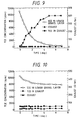
- Fig. 9 is a graph showing the change of TCE concentration in Example 5.
- Fig. 10 is a graph showing the change of TCE concentration in Comparative Example 4.
- soil 10 contains soil region 19 containing a volatile pollutant.
- a hollow, tubular and open-ended probe 21 is so constructed that it can reach the soil region 19.
- soil is packed by driving the probe into the soil.
- the soil packed in the probe contains a microorganism which can degrade the volatile pollutant, thereby forming remediation site 18 for the volatile pollutant.
- the microorganisms can be those which are not originally present in the soil, or those which are native to the soil region.
- the remediation site 18 can be formed by injecting the microorganisms through, for example, a Manchette tube 13, into the packed soil in the probe 21.
- the remediation site 18 is formed by driving the probe into the soil 10.
- the microorganisms which can degrade volatile pollutants include various microorganisms capable of degrading organochlorine compounds, as recited in the Related Art.
- strain J1 and strain JM1 which were isolated from soil and have high applicability to soil, are preferable for the present invention.
- Strain J1 and strain JM1 have been deposited in the National Institute of Bioscience and Human-Technology, Agency of Industrial Science and Technology, Ministry of International Trade and Industry (1-3, 1-chome, Azuma, Tsukuba-shi, Ibaraki-ken, Japan) as international deposit under the Treaty of Budapest. Their deposit numbers and deposit dates are as follows;
- a native or non-native microorganism it is preferable to inject at least a liquid or a gas which can activate the microorganism through Manchette tube 13 into the remediation site 18, in order to accelerate the degradation of the pollutant.
- An example of the liquid which can activate the microorganism is a treating agent containing an inducer which induces the expression of pollutant-degradation activity in the microorganism, a nutrient for microbial growth and a growth stimulating agent which stimulates the growth of microorganism.
- an inducer which induces the expression of pollutant-degradation activity in the microorganism
- a nutrient for microbial growth and a growth stimulating agent which stimulates the growth of microorganism.
- the inducer can be aromatic compounds such as phenol and toluene
- the nutrient can be citric acid
- the growth stimulating agent can be fine particles of bentonite and the like.
- Examples of a gas which can activate the microorganism include oxygen and a gas containing the above-mentioned inducer, nutrient and growth stimulating agent.
- a valve of the Manchette tube 13 is closed to cut the air flow from above the ground to the probe, a vacuum pump is attached to the upper end of the probe to suck the air in the soil so that the volatile pollutant contained in the soil region 19 is introduced to the remediation site in the probe.
- the speed of the air flow through the probe is determined by the suction power of the vacuum pump and the porosity rate of the soil.
- the porosity rate depends on the degree of consolidation and the water content of the soil. If the soil is an average sandy soil having a wet consolidation degree of 1.9 g/cm 3 and a water content of 15%, the moving speed of the air can be 10 cm/min when a powerful pump is used. It is preferable, however, to control the amount of the air sucked by the pump so that the pollutant concentration in the exhaust is always below a certain standard level. If the contact time between the pollutant and the microorganism is too short, a part of the pollutant fails to be degraded and remains in the exhaust.
- the degrading activity of the pollutant-degrading microorganism may be low for several days after the suction started.
- the suction amount of the air by the pump is preferably diminished to control the pollutant concentration in the exhaust air below the standard level.
- the treating agent containing a necessary nutrient and the like can be re-injected through the Manchette tube, and after the degradative activity of the microorganism is raised, the suction can be carried out again.
- the tubular probe together with the soil inside can be removed from the soil 10 and the soil in the probe can be treated. If there is no concern about the secondary contamination, only the vacuum pump at the top of the probe is removed and the probe may be left in the soil 10.
- the present invention allows very efficient degradation of the volatile pollutant to remedy the soil, without causing secondary contamination due to the remediation process.
- a glass column 1 having an inner diameter of 30 mm, a length of 1000 mm and threaded ends was prepared, as well as three screw caps for them.
- a Teflon coated rubber gasket was provided inside, a pin-hole was provided at the center of the cap and the gasket, and silicone tube 2 having a diameter of 0.7 mm was passed through the hole. The remaining one cap was used as a temporary cap.
- the initial bacterial number of the soil counted using 2 ⁇ YT agar medium was 4.5 ⁇ 10 4 cells/g (based on dry soil).
- the composition of 2 ⁇ YT medium was as follows: Polypeptone 16 g/l Yeast extract 10 g/l NaCl 5 g/l.
- Nutrient solution composition for degrading bacteria Minimal medium of double concentration (2 ⁇ M9) Na 2 HPO 4 12.4 g/l KH 2 PO 4 6.0 g/l NaCl 1.0 g/l NH 4 Cl 2.0 g/l Sodium citrate 10.0 g/l Phenol 0.3 g/l Dispersion of the degradative bacterium (strain J1): final concentration 2 ⁇ 10 9 cells/l
- the soil was packed into the column as follows: gravel of about 5 to 10 mm diameter was put in the column to 100 mm high from the lower end which was closed with a temporary cap, then 1280 g of the above-mentioned wet soil was compacted to 800 mm high from the top surface of the gravel layer, and the column was again packed with gravel to the top end and closed with a cap having a Teflon tube 2 passing through it. Then the temporary cap at the lower end of the column was replaced with the cap having the Teflon tube passing through it.
- the wet consolidation degree of the soil was 1.6 g/cm 3 .
- the prepared column was fixed upright on a tripod and connected to a pump 3 (Roller Pump RP-MRF1, a product of FURUE SCIENCE Co., Ltd.).
- a tank 4 containing clean water was connected to an air inlet.
- FIG. 2 A schematic illustration showing the construction of the apparatus given in Fig. 2. The apparatus was allowed to stand under this condition at room temperature for 48 hours while air was sent at 2 ml/min (period for growing degradative bacteria).
- a reservoir 5 comprising a 27 ml vial containing 15 ml of 1000 ppm trichloroethylene aqueous solution, and an empty 1000 ml glass bottle 6 for replenishing oxygen, were provided and each of them was closed with a cap having a Teflon coat rubber gasket, which was provided with two pin holes through which two Teflon tubes 2 were passed through.
- the TCE reservoir 5, the empty bottle 6 and the pump 3 were connected to the above-mentioned column which had been allowed to stand for 48 hours as shown in Fig. 3, and air containing TCE vapor was sent to the column 1 at 30 ml/min for 24 hours.
- the air in the TCE reservoir tank was first sampled 30 minutes after the sending of the air containing TCE vapor was started, and then sampled every 60 minutes, and the TCE concentration was measured by gas chromatography. TCE gradually decreased from the beginning of the measurement and the gas phase concentration reached 1 ppm or less within about 24 hours.
- the result of the measurement of the gas phase TCE concentration is shown in Fig. 4. After the TCE degradation experiment was over, the number of the bacteria in the column was counted using 2 ⁇ YT agar medium, and it was 2.3 ⁇ 10 8 cells/g (based on dry soil).
- a packed column was prepared as in Example 1 except that sterilized water was added to the soil instead of the degradative microorganism in a nutrient solution used Example 1 to adjust the water content to 16.3%.
- the column was fixed upright on a tripod and air was sent at 2 ml/min for 48 hours at room temperature, then a TCE reservoir 5 and an empty bottle 6 were connected thereto as shown in Fig. 3 and TCE degradation experiment was carried out for 24 hours.
- the measurement of TCE was carried out in the same manner as in Example 1. TCE concentration was reduced only slightly. The results are shown in Fig. 4.
- the number of the bacteria in the column after the TCE degradation was counted using 2 ⁇ YT agar medium and it was 4.6 ⁇ 10 4 cells/g (based on dry soil).
- An experimental artificial soil was prepared in an experimental tank (inside dimensions: 3 m ⁇ 3 m ⁇ 3 m, inner surface lined with a vinyl ester resin) as shown in Fig. 5.
- the preparation process will be illustrated as follows. Firstly, a layer of gravel (average size of 3 cm) was laid on the bottom of the experimental tank 50 in a thickness of about 30 cm. Then four compressed fine sand layers (average wet consolidation degree of 1.8 g/cm 3 ) were prepared (average water content of 13 %) in a thickness of about 60 cm each. Then on the top of them, a gravel layer of about 30 cm thickness was prepared in a similar way as the lower-most layer to provide an experimental artificial soil. During the preparation of this artificial soil, a stainless pipe having an inner diameter of 50 mm reaching the lower gravel layer was installed (not shown in the figure).
- a stainless tubular probe having an inner diameter of 200 mm, a length of 3 m was installed into the above-mentioned artificial soil (driven from the upper surface of the artificial soil to the point 2.4 m below the surface), and a Manchette tube for injection of a solution was installed inside of the probe.
- the Manchette tube used in this example was a 19.05 mm (3/4 inch) iron tube, having one outlet port in vertical direction which was protected with a rubber sleeve. Packers and the like were not used and the solution was directly introduced into the Manchette tube under pressure.
- the experimental tank was closed with a concrete lid, then completely sealed by coating a urethane resin thereon.
- the solution composition was as follows: Minimal medium of double concentration (2 ⁇ M9) Na 2 HPO 4 12.4 g/l KH 2 PO 4 6.0 g/l NaCl 1.0 g/l NH 4 Cl 2.0 g/l Sodium citrate 10.0 g/l Phenol 0.3 g/l. Dispersion of the degradative bacterium (strain J1): final concentration: 3.2 ⁇ 10 9 cells/l
- the vacuum pump 15 connected to the upper end of the probe (exhaust port) was started (air inlets 7 were opened and the Manchette tube for solution injection was closed), and the TCE concentrations in the air exhaust from the pump and in the air of the lower gravel layer of the experimental tank, as well as the quantity of the exhaust from the pump, were determined and recorded regularly.
- the results of the measurement are shown in Fig. 6.
- the measurement of the TCE concentration was carried out using a detector tube.
- the quantity of the exhaust from the pump was controlled such that the TCE concentration in the exhaust air did not exceed 1 ppm.
- the 2 ⁇ YT agar medium composition was as follows: Polypeptone 16.0 g/l Yeast extract 10.0 g/l NaCl 5.0 g/l Agarose 11.0 g/l.
- An experimental tank with a remediation apparatus and the ground equipment was prepared in the same manner as in Example 2, except that 20 l of tap water was injected instead of the nutrient solution.
- the tank was left for 24 hours (soil temperature 16°C), and then 30 l of 700 ppm trichloroethylene aqueous solution was injected as a pollutant into the lower gravel layer of the experimental soil through a stainless pipe installed when the soil was prepared.
- the vacuum pump was started (air inlets were opened and the Manchette tube for solution injection was closed), and the TCE concentrations in the air exhaust from the pump and in the air of the lower gravel layer of the experimental tank, as well as the quantity of the exhaust from the pump, were determined and recorded regularly.
- the results of the measurement are shown in Fig. 7.
- the measurement of the TCE concentration was carried out using a detector tube as in Example 2.
- the quantity of the exhaust from the pump was controlled such that the TCE concentration in the exhaust air did not exceed 1000 ppm.
- the exhaust air was finally passed through an activated charcoal tank and the TCE concentration in the air was made not to exceed 1 ppm.
- Fig. 7 shows, the native soil bacteria in the probe hardly have TCE degradation ability, and when the air was sucked using a vacuum pump from the upper end of the probe, the TCE concentration in the exhaust air easily exceeded 1000 ppm, accordingly, the amount of the exhaust air could not be increased.
- the remediation apparatus was removed from the experimental tank and the soil near the bottom of the apparatus was sampled.
- the number of the bacteria in the soil in the removed remediation apparatus wherein the injected solution had reached was counted and it was 2.6 ⁇ 10 5 cells/g (based on dry soil).
- a packed glass column was prepared in the same manner as in Example 1, except that the degradative bacterium was strain JM1 and phenol (an inducer) was not included in the feeding solution.
- the column was fixed upright on a tripod as in Example 1 and air was sent at 2 ml/min for 48 hours at room temperature. Then a TCE reservoir was connected to send TCE to the column to carry out TCE degradation experiment for 24 hours. TCE measurement was carried out in the same manner as in Example 1. The TCE concentration in the gas exhaust was always below the detection limit.
- One glass column 1 having an inner diameter of 30 mm, a length of 1000 mm and threaded ends, three screw caps for them were prepared.
- a Teflon coated rubber gasket was provided inside, a pin-hole was provided at the center of the cap and the gasket, and silicone tube 2 having a diameter of 0.7 mm was passed through the hole.
- the remaining one cap was used as a temporary cap.
- composition of 2 ⁇ YT medium Polypeptone 16 g/l Yeast extract 10 g/l NaCl 5 g/l Composition of 2 ⁇ M9 medium Na 2 HPO 4 12.4 g/l KH 2 PO 4 6.0 g/l NaCl 1.0 g/l NH 4 Cl 2.0 g/l
- the soil was packed into the column as follows; gravel of about 5 to 10 mm diameter was put in the column to 100 mm high from the lower end which was closed with a temporary cap, then 1280 g of the above-mentioned wet soil was compacted to 800 mm high from the top surface of the gravel layer, and the column was again packed with gravel to the top end and closed with a cap having a Teflon tube 2 passing through it. Then the temporary cap at the lower end of the column was replaced with the cap having the Teflon tube passing through it.
- the wet consolidation degree of the soil was 1.6 g/cm 3 .
- the prepared column was fixed upright on a tripod and connected to a pump (Roller Pump RP-MRF1, a product of FURUE SCIENCE Co., Ltd.).
- a tank containing clean water was connected to an air inlet.
- FIG. 2 A schematic illustration showing the construction of the apparatus given in Fig. 2. The apparatus was allowed to stand under this condition at room temperature for 48 hours while air was sent at 2 ml/min (period for growing degradative bacteria).
- a reservoir, a 27 ml vial containing 15 ml of 1000 ppm trichloroethylene aqueous solution, and an empty 1000 ml glass bottle for replenishing oxygen were provided and each of them was closed with a cap having a Teflon coat rubber gasket, which was provided with two pin holes through which two Teflon tubes were passed through.
- the TCE reservoir, the empty bottle and the pump were connected to the above-mentioned column which had been allowed to stand for 48 hours as shown in Fig. 2, and air containing TCE vapor was sent to the column at 30 ml/min for 24 hours.
- the air in the TCE reservoir tank was first sampled 30 minutes after the sending of the air containing TCE vapor was started, and then the air was sampled every 60 minutes, and the TCE concentration was measured by gas chromatography. TCE concentration gradually decreased from the beginning of the measurement and the gas phase concentration reached 1 ppm or less after about 24 hours.
- the result of the measurement of the gas phase TCE concentration is shown in Fig. 8. After the TCE degradation experiment was over, the number of the bacteria in the column was counted using 2 ⁇ YT agar medium, and it was 1.8 ⁇ 10 8 cells/g (based on dry soil).
- Example 4 instead of the nutrient solution, sterilized water was added to a soil similar to that used in Example 4 and the water content was controlled to 16.3%, and the soil was packed in a glass column to show the wet consolidation degree of 1.6 g/cm 3 and an apparatus similar to that used in Example 4 was assembled.
- the column was fixed upright on a tripod and air was sent at 2 ml/min for 48 hours at room temperature, then TCE reservoir and an empty bottle were connected to the column and TCE degradation experiment was carried out for 24 hours.
- the measurement of TCE was carried out in the same manner as in Example 1. TCE concentration was only slightly reduced. The results are shown in Fig. 8. After the TCE degradation experiment, the number of the bacteria in the column was counted using 2 ⁇ YT agar medium, and it was 4.1 ⁇ 10 4 cells/g (based on dry soil).
- An experimental artificial soil was prepared in a process exactly analogous to that used in Example 2.
- the above ground equipment shown in Fig. 1 was installed on the experimental soil and after all the preparations for the experiment were finished, 20 1 of a nutrient solution was introduced under pressure by the injection pump.
- the solution composition was as follows.
- the vacuum pump was started (air inlets were liberated and the solution injecting Manchette tube was closed), and a TCE concentration in air from the remediation apparatus upper exhaust port and a TCE concentration in air in the lower gravel layer of the experimental tank, and the amount of the exhaust air from the exhaust port at the top of the remediation apparatus were recorded regularly.
- the results of the measurement are shown in Fig. 9.
- the measurement of the TCE concentration was carried out using a detector tube.
- the amount of the exhaust air from the pump was controlled by the TCE concentration in the exhaust air such that the TCE concentration in the exhaust air did not exceed 1 ppm.
- the tubular remediation apparatus was removed from the experimental tank and the soil near the bottom of the tubular remediation apparatus was sampled. As a result of the analysis of the collected soil, phenol and sodium citrate and the like were not detected to confirm that there was no secondary contamination caused in the environment by the remedying process.
- the number of the bacteria in the collected soil was determined by dilution plate count using 2 ⁇ YT agar medium and it was 2.3 ⁇ 10 5 cells/g (based on dry soil).
- the number of the bacteria in the soil within the removed remediation apparatus wherein the injected solution had reached was similarly counted and it was 8.7 ⁇ 10 8 cells/g (based on dry soil).
- the 2 ⁇ YT agar medium composition was as follows: Polypeptone 16.0 g/l Yeast extract 10.0 g/l NaCl 5.0 g/l Agarose 11.0 g/l
- the present Example showed that degradation of the pollutant can be efficiently carried out without causing secondary contamination according to the present invention.
- Example 5 An experimental tank similar to that used in Example 5 was provided and a remediation apparatus and above ground equipment were prepared. Then 20 l of tap water was injected instead of the nutrient solution. It was allowed to stand for 24 hours (soil temperature was 16°C), then 30 l of 700 ppm trichloroethylene aqueous solution was injected as a pollutant into the lower gravel layer of the experimental soil using a stainless pipe installed when the soil was prepared.
- the vacuum pump was started (air inlets were opened and the Manchette tube for solution injection was closed), and the TCE concentrations in the air exhaust from the pump and in the air of the lower gravel layer of the experimental tank, as well as the quantity of the exhaust from the pump, were determined and recorded regularly.
- the results of the measurement are shown in Fig. 10.
- the measurement of the TCE concentration was carried out using a detector tube as in Example 5.
- the quantity of the exhaust from the pump was controlled such that the TCE concentration in the exhaust air did not exceed 1000 ppm.
- the exhaust air was finally passed through an activated charcoal tank and the TCE concentration in the air was made not to exceed 1 ppm.
- the results of the measurement are shown in Fig. 10.
- the measurement of the TCE concentration was carried out using a detector tube as in Example 5.
- the apparatus was removed from the experimental tank and the soil near the bottom of the apparatus was sampled.
- the number of the bacteria in the sampled soil determined by dilution plate count as in Example 5, was 2.5 ⁇ 10 5 cells/g (based on dry soil).
- the number of the bacteria in the soil within the removed remediation apparatus wherein the injected solution reached was similarly counted and it was 2.7 ⁇ 10 5 cells/g (based on dry soil).
Landscapes
- Life Sciences & Earth Sciences (AREA)
- Engineering & Computer Science (AREA)
- Health & Medical Sciences (AREA)
- Biomedical Technology (AREA)
- Biotechnology (AREA)
- General Health & Medical Sciences (AREA)
- Microbiology (AREA)
- Molecular Biology (AREA)
- Mycology (AREA)
- Soil Sciences (AREA)
- Environmental & Geological Engineering (AREA)
- Processing Of Solid Wastes (AREA)
Claims (14)
- Procédé de remise en état d'une région sub-superficielle du sol (19) contaminée par un polluant volatil, comprenant les étapes consistant à :caractérisé en ce que cette étape (a) comprend le remplissage de l'espace creux de la sonde (21) avec le sol de l'emplacement.(a) mettre en place une sonde tubulaire creuse (21) dans un emplacement tel qu'une des extrémités de la sonde (21) atteigne la région sub-superficielle contaminée du sol (19) ;(b) former un emplacement de remise en état (18) contenant un microorganisme dans l'espace creux de la sonde (21), le microorganisme étant capable de dégrader le polluant volatil ;(c) introduire le polluant volatil à l'emplacement de remise en état (18) de la sonde (21) depuis le sol (10), et(d) dégrader le polluant volatil avec le microorganisme présent dans la sonde (21) ;
- Procédé selon la revendication 1, dans lequel l'étape (b) comprend l'étape secondaire d'introduction du microorganisme dans le sol remplissant l'espace creux de la sonde (21).
- Procédé selon la revendication 2, dans lequel l'étape (b) comprend en outre l'étape secondaire d'activation du microorganisme introduit dans le sol remplissant l'espace creux de la sonde (21).
- Procédé selon la revendication 1, dans lequel le microorganisme est un microorganisme naturel qui est indigène au sol (10) et qui vit dans le sol remplissant l'espace creux de la sonde (21).
- Procédé selon la revendication 1, dans lequel l'étape (b) comprend l'étape secondaire d'activation du microorganisme naturel présent dans le sol remplissant l'espace creux de la sonde (21).
- Procédé selon les revendications 3 ou 5, dans lequel l'agent d'activation comprend l'introduction d'un liquide ou d'un gaz pour la croissance microbienne dans l'emplacement de remise en état (18) de la sonde (21).
- Procédé selon la revendication 6, dans lequel le liquide est choisi dans le groupe constitué d'un agent nutritif, d'un inducteur et d'un agent stimulant la croissance.
- Procédé selon la revendication 6, dans lequel le gaz est choisi dans le groupe constitué de l'oxygène, d'un inducteur et d'un agent stimulant la croissance.
- Procédé selon la revendication 1, dans lequel l'étape (c) est effectuée en aspirant le polluant volatil de la région sub-superficielle du sol.
- Procédé selon la revendication 1, dans lequel le polluant contient un hydrocarbure.
- Procédé selon la revendication 10, dans lequel l'hydrocarbure contient au moins un composé aliphatique chloré ou un composé aromatique.
- Procédé selon la revendication 11, dans lequel le composé aliphatique chloré est au moins le trichloréthylène ou le tétrachloréthylène.
- Procédé selon la revendication 1, dans lequel la sonde contient un tube de Manchette (13).
- Appareil pour la remise en état d'une région sub-superficielle du sol (19) contaminée par un polluant volatil comprenant :caractérisé en ce que cette sonde (21) est un tube creux et en ce que cette première extrémité de cette sonde (21) est ouverte.(a) une sonde (21) ayant une première et une seconde extrémités ;(b) un moyen (13) pour injecter au moins un microorganisme capable de dégrader le polluant volatil et un agent nutritif pour un microorganisme capable de dégrader le polluant volatil à l'intérieur de l'échantillon (21) ; et(c) un moyen d'aspiration des gaz (15) qui peut être connecté à une ouverture à cette seconde extrémité de la sonde (21) pour abaisser la pression interne de la sonde (21) ;
Applications Claiming Priority (6)
| Application Number | Priority Date | Filing Date | Title |
|---|---|---|---|
| JP09148796A JP3217693B2 (ja) | 1996-04-12 | 1996-04-12 | 汚染土壌の浄化方法及び汚染土壌の浄化装置 |
| JP09149296A JP3217694B2 (ja) | 1996-04-12 | 1996-04-12 | 汚染土壌浄化方法及び装置 |
| JP91492/96 | 1996-04-12 | ||
| JP9149296 | 1996-04-12 | ||
| JP9148796 | 1996-04-12 | ||
| JP91487/96 | 1996-04-12 |
Publications (3)
| Publication Number | Publication Date |
|---|---|
| EP0800873A2 EP0800873A2 (fr) | 1997-10-15 |
| EP0800873A3 EP0800873A3 (fr) | 1998-08-26 |
| EP0800873B1 true EP0800873B1 (fr) | 2001-12-19 |
Family
ID=26432925
Family Applications (1)
| Application Number | Title | Priority Date | Filing Date |
|---|---|---|---|
| EP97302449A Expired - Lifetime EP0800873B1 (fr) | 1996-04-12 | 1997-04-09 | Procédé et dispositif pour la décontamination des sols |
Country Status (3)
| Country | Link |
|---|---|
| US (1) | US5906932A (fr) |
| EP (1) | EP0800873B1 (fr) |
| DE (1) | DE69709213T2 (fr) |
Families Citing this family (8)
| Publication number | Priority date | Publication date | Assignee | Title |
|---|---|---|---|---|
| US6458276B1 (en) * | 2001-05-16 | 2002-10-01 | Shell Oil Company | Method and apparatus for biodegradation of alkyl ethers and tertiary butyl alcohol |
| US7645606B2 (en) * | 2002-03-25 | 2010-01-12 | Pha Environmental Restoration | In situ biodegradation of subsurface contaminants by injection of phosphate nutrients and hydrogen |
| US20060094106A1 (en) * | 2002-03-25 | 2006-05-04 | Priester Lamar E Iii | Biodegradation of subsurface contaminants by injection of gaseous microbial metabolic inducer |
| US6783673B2 (en) * | 2002-08-23 | 2004-08-31 | Biotage, Inc. | Composite chromatography column |
| US20040229342A1 (en) * | 2003-05-16 | 2004-11-18 | Ken Lunde | Process for remediation of hydrocarbons |
| US7108455B1 (en) * | 2005-05-10 | 2006-09-19 | Gas Technology Institute | Carbureted bioventing for enhanced control of in-situ bioremediation |
| US20090011413A1 (en) * | 2005-12-14 | 2009-01-08 | Canon Kabushiki Kaisha | Method for screening colon cancer cells and gene set used for examination of colon cancer |
| US8187803B2 (en) * | 2006-03-31 | 2012-05-29 | Canon Kabushiki Kaisha | Probe, probe set, probe-immobilized carrier, and genetic testing method |
Family Cites Families (26)
| Publication number | Priority date | Publication date | Assignee | Title |
|---|---|---|---|---|
| JPS51148283A (en) * | 1975-06-14 | 1976-12-20 | Mamoru Kawaguchi | Blood circulation accelerator |
| DE3721981A1 (de) * | 1987-07-03 | 1989-01-12 | Norddeutsche Seekabelwerke Ag | Verfahren und vorrichtung zur beseitigung von verunreinigungen im boden |
| US5017289A (en) * | 1987-09-25 | 1991-05-21 | Chevron Research & Technology Company | Process for in situ biodegradation of hydrocarbon contaminated soil |
| US5006250A (en) * | 1987-12-04 | 1991-04-09 | The Board Of Trustees Of The Leland Stanford Junior University | Pulsing of electron donor and electron acceptor for enhanced biotransformation of chemicals |
| JPH0650980B2 (ja) * | 1988-09-27 | 1994-07-06 | 国立環境研究所長 | 脂肪族塩素化合物の微生物的分解方法及びその微生物 |
| US4877736A (en) * | 1988-10-12 | 1989-10-31 | The United States Of Americal As Represented By The United States Department Of Energy | Aerobic microorganism for the degradation of chlorinated aliphatic hydrocarbons |
| US4925802A (en) * | 1988-12-21 | 1990-05-15 | Ecova Corporation | Method for stimulating biodegradation of halogenated aliphatic hydrocarbons |
| JPH02273599A (ja) * | 1989-04-15 | 1990-11-08 | Okada Susumu | トリハロメタン類の分解法 |
| US5080782A (en) * | 1989-06-08 | 1992-01-14 | Environmental Science & Engineering, Inc. | Apparatus for bioremediation of sites contaminated with hazardous substances |
| US4992174A (en) * | 1989-06-08 | 1991-02-12 | Environmental Science & Engineering, Inc. | Fixed bed bioreactor remediation system |
| US5472294A (en) * | 1990-03-28 | 1995-12-05 | Environmental Improvement Technologies, Inc. | Contaminant remediation, biodegradation and volatilization methods and apparatuses |
| JPH0667314B2 (ja) * | 1990-04-11 | 1994-08-31 | 国立環境研究所長 | 脂肪族塩素化合物の微生物分解方法及びその微生物 |
| US5334533A (en) * | 1990-05-07 | 1994-08-02 | Colasito Dominic J | Oil contamination clean-up by use of microbes and air |
| DE4021814A1 (de) * | 1990-05-23 | 1991-11-28 | Ieg Ind Engineering Gmbh | Anordnung zur gasbehandlung von verunreinigtem erdreich |
| CZ279021B6 (en) * | 1992-04-15 | 1994-11-16 | Bfb Technologie Anstalt | Mixture of micro-organisms capable of biological degradation of hydrocarbons and method hydrocarbon biological degradation |
| US5614410A (en) * | 1992-07-14 | 1997-03-25 | Sbp Technologies, Inc. | Bioremediation of soil or groundwater contaminated with compounds in creosote by two-stage biodegradation |
| JP3318977B2 (ja) * | 1992-08-27 | 2002-08-26 | 栗田工業株式会社 | シュードモナス プチダ ferm p−13109菌株 |
| AU679691B2 (en) * | 1992-08-27 | 1997-07-10 | United States Department Of Energy | Bioremediation of contaminated groundwater |
| JPH06227769A (ja) * | 1993-02-02 | 1994-08-16 | Toshiba Corp | エレベータの自家発電管制運転制御装置 |
| JPH06254537A (ja) * | 1993-03-03 | 1994-09-13 | Toshiba Corp | 地下水浄化方法及びその装置 |
| DE4335574A1 (de) * | 1993-08-30 | 1995-03-02 | Biopract Gmbh | Verfahren zur Entfernung von Schadstoffablagerungen in flüssigen, fest-flüssigen und festen, wasserdurchlässigen Umgebungen |
| WO1995008513A1 (fr) * | 1993-09-24 | 1995-03-30 | Sbp Technologies, Inc. | Biocomposite comprenant un micro-organisme ainsi qu'un additif dans une matrice de formulation de biorestauration et de lutte antipollution |
| JP3222658B2 (ja) * | 1993-10-18 | 2001-10-29 | 株式会社竹中工務店 | 汚染土壌修復装置及びそれを用いた汚染土壌修復方法 |
| JP3348948B2 (ja) * | 1993-12-28 | 2002-11-20 | 呉羽化学工業株式会社 | 土壌中有機溶剤の除去装置 |
| US5560737A (en) * | 1995-08-15 | 1996-10-01 | New Jersey Institute Of Technology | Pneumatic fracturing and multicomponent injection enhancement of in situ bioremediation |
| US5577558A (en) * | 1995-10-16 | 1996-11-26 | General Motors Corporation | In-well device for in situ removal of underground contaminants |
-
1997
- 1997-04-09 DE DE69709213T patent/DE69709213T2/de not_active Expired - Lifetime
- 1997-04-09 EP EP97302449A patent/EP0800873B1/fr not_active Expired - Lifetime
- 1997-04-10 US US08/831,695 patent/US5906932A/en not_active Expired - Lifetime
Also Published As
| Publication number | Publication date |
|---|---|
| EP0800873A3 (fr) | 1998-08-26 |
| DE69709213D1 (de) | 2002-01-31 |
| EP0800873A2 (fr) | 1997-10-15 |
| US5906932A (en) | 1999-05-25 |
| DE69709213T2 (de) | 2002-06-13 |
Similar Documents
| Publication | Publication Date | Title |
|---|---|---|
| EP0822253B1 (fr) | Souche microbiologique, procédé pour la biodégradation de composés organiques et procédé pour la décontamination de l'environnement en utilisant celle-ci | |
| US6319706B1 (en) | Process and apparatus for remedying polluted media | |
| EP0822252B1 (fr) | Souches microbiologiques, procédé pour la biodégradation de composés organiques et procédé pour la décontamination | |
| JP3083077B2 (ja) | 有機化合物の生分解方法及び環境修復方法 | |
| EP0800873B1 (fr) | Procédé et dispositif pour la décontamination des sols | |
| CA2255437C (fr) | Procede pour la restauration de sols contamines | |
| JP3217694B2 (ja) | 汚染土壌浄化方法及び装置 | |
| JP3645650B2 (ja) | リアクタ型汚染土壌浄化方法及び装置 | |
| JPH09276837A (ja) | 汚染土壌浄化方法 | |
| JP3217693B2 (ja) | 汚染土壌の浄化方法及び汚染土壌の浄化装置 | |
| JPH09276836A (ja) | カセット型リアクタ式汚染土壌浄化装置及びそれを用いた土壌浄化方法 | |
| JPH09276840A (ja) | 汚染土壌浄化方法 | |
| JP3461238B2 (ja) | 有機化合物の生分解方法および環境修復方法 | |
| JP3673662B2 (ja) | 汚染土壌の修復方法 | |
| JPH09271749A (ja) | 適合溶質を用いた微生物による汚染土壌の生物的修復方法 | |
| JPH09267082A (ja) | 汚染土壌の浄化方法 | |
| JPH09276835A (ja) | 汚染土壌浄化方法 | |
| JP3618785B2 (ja) | 微生物破砕物を用いた汚染土壌の浄化方法 | |
| JPH09276834A (ja) | 汚染土壌浄化方法 | |
| JPH10295366A (ja) | 新規な過酸化水素耐性微生物、その取得方法及びそれを用いた汚染媒体の修復方法 | |
| JP2000140869A (ja) | 希釈率を制御するリアクターによる有機塩素化合物汚染の生物的修復浄化方法および装置 | |
| JPH09267083A (ja) | 汚染土壌の生物的修復浄化方法 | |
| JPH11113563A (ja) | 有機化合物で汚染された環境の微生物による分解浄化修復方法 | |
| JPH09201581A (ja) | 有機化合物の分解方法、有機化合物の分解装置、微生物の単離方法および新規微生物 | |
| JP2000189944A (ja) | 揮発性汚染物質分解方法 |
Legal Events
| Date | Code | Title | Description |
|---|---|---|---|
| PUAI | Public reference made under article 153(3) epc to a published international application that has entered the european phase |
Free format text: ORIGINAL CODE: 0009012 |
|
| AK | Designated contracting states |
Kind code of ref document: A2 Designated state(s): DE FI FR GB NL |
|
| PUAL | Search report despatched |
Free format text: ORIGINAL CODE: 0009013 |
|
| AK | Designated contracting states |
Kind code of ref document: A3 Designated state(s): DE FI FR GB NL |
|
| 17P | Request for examination filed |
Effective date: 19990114 |
|
| 17Q | First examination report despatched |
Effective date: 19991222 |
|
| GRAG | Despatch of communication of intention to grant |
Free format text: ORIGINAL CODE: EPIDOS AGRA |
|
| GRAG | Despatch of communication of intention to grant |
Free format text: ORIGINAL CODE: EPIDOS AGRA |
|
| GRAH | Despatch of communication of intention to grant a patent |
Free format text: ORIGINAL CODE: EPIDOS IGRA |
|
| GRAH | Despatch of communication of intention to grant a patent |
Free format text: ORIGINAL CODE: EPIDOS IGRA |
|
| GRAA | (expected) grant |
Free format text: ORIGINAL CODE: 0009210 |
|
| AK | Designated contracting states |
Kind code of ref document: B1 Designated state(s): DE FI FR GB NL |
|
| PG25 | Lapsed in a contracting state [announced via postgrant information from national office to epo] |
Ref country code: FI Free format text: LAPSE BECAUSE OF FAILURE TO SUBMIT A TRANSLATION OF THE DESCRIPTION OR TO PAY THE FEE WITHIN THE PRESCRIBED TIME-LIMIT Effective date: 20011219 |
|
| REG | Reference to a national code |
Ref country code: GB Ref legal event code: IF02 |
|
| REF | Corresponds to: |
Ref document number: 69709213 Country of ref document: DE Date of ref document: 20020131 |
|
| PLBE | No opposition filed within time limit |
Free format text: ORIGINAL CODE: 0009261 |
|
| STAA | Information on the status of an ep patent application or granted ep patent |
Free format text: STATUS: NO OPPOSITION FILED WITHIN TIME LIMIT |
|
| 26N | No opposition filed | ||
| REG | Reference to a national code |
Ref country code: FR Ref legal event code: PLFP Year of fee payment: 20 |
|
| PGFP | Annual fee paid to national office [announced via postgrant information from national office to epo] |
Ref country code: NL Payment date: 20160310 Year of fee payment: 20 |
|
| PGFP | Annual fee paid to national office [announced via postgrant information from national office to epo] |
Ref country code: FR Payment date: 20160309 Year of fee payment: 20 |
|
| PGFP | Annual fee paid to national office [announced via postgrant information from national office to epo] |
Ref country code: GB Payment date: 20160406 Year of fee payment: 20 Ref country code: DE Payment date: 20160405 Year of fee payment: 20 |
|
| REG | Reference to a national code |
Ref country code: DE Ref legal event code: R071 Ref document number: 69709213 Country of ref document: DE |
|
| REG | Reference to a national code |
Ref country code: NL Ref legal event code: MK Effective date: 20170408 |
|
| REG | Reference to a national code |
Ref country code: GB Ref legal event code: PE20 Expiry date: 20170408 |
|
| PG25 | Lapsed in a contracting state [announced via postgrant information from national office to epo] |
Ref country code: GB Free format text: LAPSE BECAUSE OF EXPIRATION OF PROTECTION Effective date: 20170408 |