EP0801244B1 - Hydrodynamische Kupplung - Google Patents
Hydrodynamische Kupplung Download PDFInfo
- Publication number
- EP0801244B1 EP0801244B1 EP97103679A EP97103679A EP0801244B1 EP 0801244 B1 EP0801244 B1 EP 0801244B1 EP 97103679 A EP97103679 A EP 97103679A EP 97103679 A EP97103679 A EP 97103679A EP 0801244 B1 EP0801244 B1 EP 0801244B1
- Authority
- EP
- European Patent Office
- Prior art keywords
- basin
- pump
- coupling
- wheel
- turbine wheel
- Prior art date
- Legal status (The legal status is an assumption and is not a legal conclusion. Google has not performed a legal analysis and makes no representation as to the accuracy of the status listed.)
- Expired - Lifetime
Links
Images

Classifications
-
- F—MECHANICAL ENGINEERING; LIGHTING; HEATING; WEAPONS; BLASTING
- F16—ENGINEERING ELEMENTS AND UNITS; GENERAL MEASURES FOR PRODUCING AND MAINTAINING EFFECTIVE FUNCTIONING OF MACHINES OR INSTALLATIONS; THERMAL INSULATION IN GENERAL
- F16D—COUPLINGS FOR TRANSMITTING ROTATION; CLUTCHES; BRAKES
- F16D33/00—Rotary fluid couplings or clutches of the hydrokinetic type
- F16D33/06—Rotary fluid couplings or clutches of the hydrokinetic type controlled by changing the amount of liquid in the working circuit
- F16D33/16—Rotary fluid couplings or clutches of the hydrokinetic type controlled by changing the amount of liquid in the working circuit by means arranged externally of the coupling or clutch
Definitions
- the invention relates to a hydrodynamic coupling with a pump wheel and a turbine wheel, both of which have a toroidal work space form with each other ..
- Hydrodynamic couplings have the advantage of an elastic one Work behavior and a smooth, relatively shock-free transmission of a Torque, for example from a motor to a conveyor belt.
- a Torque for example from a motor to a conveyor belt.
- limit or lower transmissible torque This will the engine is spared even more when starting off.
- hydrodynamic couplings are made with oil as the operating fluid operated.
- the oil heats up during operation. It must therefore be cooled.
- the oil is continuously circulated in a cooling circuit. It is passed through a heat exchanger is located outside the hydrodynamic clutch.
- the whole The hydrodynamic coupling is enclosed in a housing that a first port for draining the oil and a second port to reintroduce the oil after passing through the heat exchanger.
- a generic hydrodynamic coupling is from the document GB 2 269 221 A is known. This includes a pump wheel and a turbine wheel, which together form a toroidal work space. To the pump wheel a shell is rotatably connected, which encompasses the turbine wheel and forms with it an annular gap, which in turn with the Workspace communicates. On the bowl is an annular pump bowl connected. Operating equipment gets into this from the work area.
- the removal takes place by immersing a dip tube - so-called Back pressure pump - in the oil sump.
- the oil sump is made of a ring Shell formed, which in the operation of the hydrodynamic clutch - together with the pump wheel - rotates.
- the mouthpiece of the Back pressure pump plunges more or less deeply into the oil sump forms in the shell mentioned.
- the drive speed can be adjusted to a certain extent Range can be adjusted. It is also possible to use a special Regulation to start a work machine with constant acceleration, regardless of the load.
- a disadvantage of such couplings with dynamic pressure pumps and ring-shaped Oil bowl consists of the pump wheel and turbine wheel Toroidal working space formed when the coupling is not at a standstill completely emptied.
- the invention has for its object a coupling of the type mentioned to be designed in such a way that complete emptying of the work area possible when the clutch is switched off.
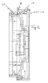
- the clutch has a pump wheel 1 and a turbine wheel 2.
- the two Together, wheels form a toroidal working space 3.
- a shell-shaped wall part 1.1 is rotationally fixed with the pump wheel 1 connected. This extends radially inwards up to an output shaft 4.
- the pump wheel itself sits on a drive shaft 5, via which Torque from a flywheel 6 and one of the Flywheel 6 upstream engine (not shown) is initiated.
- Pump wheel 1 and turbine wheel 2 are from a clutch housing 7 enclosed.
- An external circuit 8 is provided to the equipment in this Trap oil to cool during operation.
- the external circuit 8 includes a heat exchanger 8.1.
- the crucial component is a so-called Back pressure pump 8.2. This has a pipe socket 8.3 with a mouthpiece 8.4 on.
- Said shell-shaped wall part 1.1 contains an annular one Pump bowl 1.2. This is of crucial importance for the invention. As you can see, the content of the pump bowl 1.2 communicates with the Working room 3 via a connecting line 1.3.
- the pump bowl 1.2 is designed and arranged so that the mirror of the accumulating equipment radially outside the connecting line 1.3 located, but at least on the same radius as the connecting line 1.3.
- the clutch contains other components, but not of the invention are of primary importance.
- the housing 7 is designed in such a way that it can accommodate a working fluid sump 7.1.
- Valves are provided, for example the valve 10 with which the Operating characteristics of the clutch is adjustable.
- the pump bowl 1.2 is arranged radially so far outside that at The work area is at a standstill (for example when the clutch is switched off emergency) drained automatically via the connecting line 1.3.
- the working medium flows here through the connecting line 1.3 into the pump bowl 1.2, and from there over the radially inner edge of a wall 1.2.2 into the tank (Working fluid sump 7.1).
- the start-up is accordingly carried out when the work area 3 is completely empty.
Landscapes
- Engineering & Computer Science (AREA)
- General Engineering & Computer Science (AREA)
- Mechanical Engineering (AREA)
- Mechanical Operated Clutches (AREA)
- Arrangement Of Transmissions (AREA)
- General Details Of Gearings (AREA)
Description
- Fig. 1
- zeigt die Kupplung in einer Gesamtansicht.
- Fig. 2
- zeigt in vergrößerter Darstellung die das Turbinenrad umgreifende Schale mit hieran angeformter Pumpschale.
Claims (4)
- Hydrodynamische Kupplung mit regelbarem Drehmoment, mit den folgenden Merkmalen:gekennzeichnet durch die folgenden Merkmale:1.1 ein Pumpenrad (1) und ein Turbinenrad (2) bilden miteinander einen torusförmigen Arbeitsraum (3);1.2 an das Pumpenrad (1) ist eine Schale (1.1) drehfest angeschlossen, die das Turbinenrad (2) umgreift und mit diesem einen Ringspalt bildet, der seinerseits mit dem Arbeitsraum (3) kommuniziert;1.3 an die Schale (1.1) ist eine ringförmige Pumpschale (1.2) drehfest angeschlossen;1.4 es ist ein feststehendes Kupplungsgehäuse (7) vorgesehen, das die beiden Räder umgibt;1.5 die Kupplung weist einen Kühlkreislauf (8) zum Kühlen des Betriebsmittels mit einem extern zum Kupplungsgehäuse angeordneten Wärmetauscher und einen feststehenden Betriebsmittelsumpf (7.1) auf;1.6 innerhalb des Gehäuses (7) ist eine feststehende Staudruckpumpe (8.2) angeordnet, die einen in die Pumpschale (1.2) eintauchenden Rohrstutzen (8.3) aufweist;1.7. in der Wandung der Schale (1.1) ist mindestens eine Bohrung (1.3) vorgesehen, die eine leitende Verbindung zwischen dem radial äußeren Bereich des Ringspaltes zwischen Pumpenrad (1) und Turbinenrad (2) und dem Innenraum der Pumpschale (1.2) herstellt:1.8 die Pumpschale (1.2) ist derart angeordnet, daß sich die gegen den Pumpschalen-Innenraum gerichtete Mündung der Bohrung (1.3) auf demselben Radius wie der radial äußerste Punkt des Arbeitsraumes, oder auf einem größeren Radius als dieser befindet.
- Kupplung nach Anspruch 1, dadurch gekennzeichnet, daß die Pumpschale (1.2) axial durch eine Wand (1.2.2) begrenzt ist, deren Innendurchmesser größer oder gleich dem größten Innendurchmesser der Schale (1.1.8) ist.
- Kupplung nach Anspruch 1 oder 2, dadurch gekennzeichnet, daß die Schale (1.1) eine Ausdrehung aufweist, die deren Grund auf einen größeren Druchmesser legt.
- Kupplung nach einem der Ansprüche 1 bis 3, dadurch gekennzeichnet, daß die Eintauchtiefe des Rohrstutzens (8.3) der Staudruckpumpe variabel ist.
Applications Claiming Priority (2)
| Application Number | Priority Date | Filing Date | Title |
|---|---|---|---|
| DE19614588 | 1996-04-12 | ||
| DE19614588A DE19614588A1 (de) | 1996-04-12 | 1996-04-12 | Hydrodynamische Kupplung |
Publications (2)
| Publication Number | Publication Date |
|---|---|
| EP0801244A1 EP0801244A1 (de) | 1997-10-15 |
| EP0801244B1 true EP0801244B1 (de) | 2001-10-24 |
Family
ID=7791150
Family Applications (1)
| Application Number | Title | Priority Date | Filing Date |
|---|---|---|---|
| EP97103679A Expired - Lifetime EP0801244B1 (de) | 1996-04-12 | 1997-03-06 | Hydrodynamische Kupplung |
Country Status (2)
| Country | Link |
|---|---|
| EP (1) | EP0801244B1 (de) |
| DE (2) | DE19614588A1 (de) |
Cited By (1)
| Publication number | Priority date | Publication date | Assignee | Title |
|---|---|---|---|---|
| DE102014203835A1 (de) | 2014-03-03 | 2015-09-03 | Voith Patent Gmbh | Hydrodynamische Maschine und Staudruckpumpe hierfür |
Families Citing this family (3)
| Publication number | Priority date | Publication date | Assignee | Title |
|---|---|---|---|---|
| DE19902296A1 (de) * | 1999-01-21 | 2000-08-17 | Voith Turbo Kg | Hydrodynamische Kupplung |
| BR0113598A (pt) * | 2000-08-30 | 2003-07-15 | Voith Turbo Kg | Processo para o controle do consumo de potência de uma embreagem hidrodinâmica por meio do controle do grau de enchimento e de uma embreagem hidrodinâmica |
| DE10231028A1 (de) * | 2002-07-09 | 2004-01-29 | Voith Turbo Gmbh & Co. Kg | Betriebsmittelversorgungssystem für Anfahrelemente in Form hydrodynamischer Komponenten und Getriebebaueinheit |
Family Cites Families (10)
| Publication number | Priority date | Publication date | Assignee | Title |
|---|---|---|---|---|
| US2116992A (en) * | 1935-06-19 | 1938-05-10 | Bailey Meter Co | Control system |
| DE1121888B (de) * | 1952-11-06 | 1962-01-11 | Harold Sinclair | Hydrodynamische Kupplung |
| DE1136541B (de) * | 1954-07-09 | 1962-09-13 | J M Voith G M B H Maschinenfab | Hydrodynamische Kupplung |
| DE1283610B (de) * | 1966-02-24 | 1968-11-21 | Jean Raoust | Kuehlvorrichtung fuer die Arbeitsfluessigkeit eines hydrodynamischen Getriebes, insbesondere einer hydrodynamischen Kupplung |
| FR1470038A (fr) * | 1966-02-24 | 1967-02-17 | Dispositif de refroidisseur intégré pour variateur hydraulique | |
| US3703078A (en) * | 1971-04-19 | 1972-11-21 | American Standard Inc | Rapid response fluid drive |
| DE2639683C3 (de) * | 1976-09-03 | 1981-07-16 | A. Friedr. Flender Gmbh & Co Kg, 4290 Bocholt | Hydrodynamische Kupplung |
| DE3240179A1 (de) * | 1981-10-30 | 1983-06-16 | Ebara Corp., Tokyo | Stroemungsmittelkupplung |
| DE4224728C2 (de) * | 1992-07-27 | 1998-01-15 | Voith Turbo Kg | Hydrodynamische Kupplung |
| DE4311350C2 (de) * | 1993-04-06 | 1996-02-08 | Voith Turbo Kg | Hydrodynamische Kupplung |
-
1996
- 1996-04-12 DE DE19614588A patent/DE19614588A1/de not_active Withdrawn
-
1997
- 1997-03-06 DE DE59705025T patent/DE59705025D1/de not_active Expired - Lifetime
- 1997-03-06 EP EP97103679A patent/EP0801244B1/de not_active Expired - Lifetime
Cited By (1)
| Publication number | Priority date | Publication date | Assignee | Title |
|---|---|---|---|---|
| DE102014203835A1 (de) | 2014-03-03 | 2015-09-03 | Voith Patent Gmbh | Hydrodynamische Maschine und Staudruckpumpe hierfür |
Also Published As
| Publication number | Publication date |
|---|---|
| EP0801244A1 (de) | 1997-10-15 |
| DE59705025D1 (de) | 2001-11-29 |
| DE19614588A1 (de) | 1997-10-16 |
Similar Documents
| Publication | Publication Date | Title |
|---|---|---|
| DE102009039039B4 (de) | Drehschwingungsdämpfer | |
| EP0351510B1 (de) | Selbstgeregeltes Zweistufengetriebe für den Antrieb der Nebenaggregate von Kraftfahrzeugmotoren | |
| DE4316289A1 (de) | Drehmomentwandler | |
| DE3943327A1 (de) | Automatisches stufenloses getriebe fuer ein fahrzeug | |
| DE19519227A1 (de) | Getriebebaugruppe für Zugmaschinen | |
| DE10358280A1 (de) | Planetenradsatz für Automatikgetriebe | |
| DE3238780C1 (de) | Ölschmiersystem für Getriebe | |
| DE102006046487A1 (de) | Automatikgetriebe | |
| DE1943571A1 (de) | Stroemungsmittel-Betaetigungsvorrichtung | |
| EP0801244B1 (de) | Hydrodynamische Kupplung | |
| DE10336267B4 (de) | Automatikgetriebe | |
| DE112012001865T5 (de) | Reibelement, Kupplungsplatte, Kupplungsvorrichtung und Drehmomentwandler | |
| DE2254082B2 (de) | Verfahren zum Schmieren des Getriebes einer Gasturbine und Gasturbine zur Ausübung des Verfahrens | |
| DE3329854C1 (de) | Hydrodynamische Stellkupplung | |
| DE102007003055A1 (de) | Hydrodynamischer Drehmomentwandler | |
| EP4185792A1 (de) | Getriebemotor, aufweisend ein getriebe, einen elektromotor und einen adapterflansch | |
| DE2305539A1 (de) | Ventilgesteuerte hydraulische kupplung | |
| DE2247725A1 (de) | Hydrodynamische einheit | |
| DE2716124A1 (de) | Drehmomentwandler-stroemungsmittelsteueranlage | |
| DE1209145B (de) | Steuerung einer hydrodynamischen Bremse, insbesondere in Schienentriebfahrzeugen | |
| DE19851384A1 (de) | Automatisch gesteuertes Getriebe | |
| EP3830449B1 (de) | Getriebe und verfahren zum herstellen einer ersten oder einer zweiten variante eines getriebes | |
| EP0801242B1 (de) | Hydrodynamische Kupplung | |
| DE2639683A1 (de) | Hydrodynamische kupplung | |
| AT138543B (de) | Flüssigkeitskupplung bzw. -getriebe oder -bremse. |
Legal Events
| Date | Code | Title | Description |
|---|---|---|---|
| PUAI | Public reference made under article 153(3) epc to a published international application that has entered the european phase |
Free format text: ORIGINAL CODE: 0009012 |
|
| AK | Designated contracting states |
Kind code of ref document: A1 Designated state(s): DE FR GB IT |
|
| 17P | Request for examination filed |
Effective date: 19980314 |
|
| 17Q | First examination report despatched |
Effective date: 19991112 |
|
| GRAG | Despatch of communication of intention to grant |
Free format text: ORIGINAL CODE: EPIDOS AGRA |
|
| GRAG | Despatch of communication of intention to grant |
Free format text: ORIGINAL CODE: EPIDOS AGRA |
|
| GRAG | Despatch of communication of intention to grant |
Free format text: ORIGINAL CODE: EPIDOS AGRA |
|
| GRAH | Despatch of communication of intention to grant a patent |
Free format text: ORIGINAL CODE: EPIDOS IGRA |
|
| GRAH | Despatch of communication of intention to grant a patent |
Free format text: ORIGINAL CODE: EPIDOS IGRA |
|
| GRAA | (expected) grant |
Free format text: ORIGINAL CODE: 0009210 |
|
| AK | Designated contracting states |
Kind code of ref document: B1 Designated state(s): DE FR GB IT |
|
| GBT | Gb: translation of ep patent filed (gb section 77(6)(a)/1977) |
Effective date: 20011024 |
|
| REF | Corresponds to: |
Ref document number: 59705025 Country of ref document: DE Date of ref document: 20011129 |
|
| REG | Reference to a national code |
Ref country code: GB Ref legal event code: IF02 |
|
| ET | Fr: translation filed | ||
| PLBE | No opposition filed within time limit |
Free format text: ORIGINAL CODE: 0009261 |
|
| STAA | Information on the status of an ep patent application or granted ep patent |
Free format text: STATUS: NO OPPOSITION FILED WITHIN TIME LIMIT |
|
| 26N | No opposition filed | ||
| REG | Reference to a national code |
Ref country code: FR Ref legal event code: PLFP Year of fee payment: 19 |
|
| PGFP | Annual fee paid to national office [announced via postgrant information from national office to epo] |
Ref country code: DE Payment date: 20150320 Year of fee payment: 19 Ref country code: IT Payment date: 20150326 Year of fee payment: 19 |
|
| PGFP | Annual fee paid to national office [announced via postgrant information from national office to epo] |
Ref country code: GB Payment date: 20150319 Year of fee payment: 19 Ref country code: FR Payment date: 20150319 Year of fee payment: 19 |
|
| REG | Reference to a national code |
Ref country code: DE Ref legal event code: R119 Ref document number: 59705025 Country of ref document: DE |
|
| GBPC | Gb: european patent ceased through non-payment of renewal fee |
Effective date: 20160306 |
|
| REG | Reference to a national code |
Ref country code: FR Ref legal event code: ST Effective date: 20161130 |
|
| PG25 | Lapsed in a contracting state [announced via postgrant information from national office to epo] |
Ref country code: GB Free format text: LAPSE BECAUSE OF NON-PAYMENT OF DUE FEES Effective date: 20160306 Ref country code: DE Free format text: LAPSE BECAUSE OF NON-PAYMENT OF DUE FEES Effective date: 20161001 Ref country code: FR Free format text: LAPSE BECAUSE OF NON-PAYMENT OF DUE FEES Effective date: 20160331 |
|
| PG25 | Lapsed in a contracting state [announced via postgrant information from national office to epo] |
Ref country code: IT Free format text: LAPSE BECAUSE OF NON-PAYMENT OF DUE FEES Effective date: 20160306 |