EP0801255B1 - Tiroir rotative - Google Patents
Tiroir rotative Download PDFInfo
- Publication number
- EP0801255B1 EP0801255B1 EP97105016A EP97105016A EP0801255B1 EP 0801255 B1 EP0801255 B1 EP 0801255B1 EP 97105016 A EP97105016 A EP 97105016A EP 97105016 A EP97105016 A EP 97105016A EP 0801255 B1 EP0801255 B1 EP 0801255B1
- Authority
- EP
- European Patent Office
- Prior art keywords
- holes
- disc
- valve according
- hole
- teeth
- Prior art date
- Legal status (The legal status is an assumption and is not a legal conclusion. Google has not performed a legal analysis and makes no representation as to the accuracy of the status listed.)
- Expired - Lifetime
Links
Images


Classifications
-
- F—MECHANICAL ENGINEERING; LIGHTING; HEATING; WEAPONS; BLASTING
- F16—ENGINEERING ELEMENTS AND UNITS; GENERAL MEASURES FOR PRODUCING AND MAINTAINING EFFECTIVE FUNCTIONING OF MACHINES OR INSTALLATIONS; THERMAL INSULATION IN GENERAL
- F16K—VALVES; TAPS; COCKS; ACTUATING-FLOATS; DEVICES FOR VENTING OR AERATING
- F16K11/00—Multiple-way valves, e.g. mixing valves; Pipe fittings incorporating such valves
- F16K11/02—Multiple-way valves, e.g. mixing valves; Pipe fittings incorporating such valves with all movable sealing faces moving as one unit
- F16K11/06—Multiple-way valves, e.g. mixing valves; Pipe fittings incorporating such valves with all movable sealing faces moving as one unit comprising only sliding valves, i.e. sliding closure elements
- F16K11/072—Multiple-way valves, e.g. mixing valves; Pipe fittings incorporating such valves with all movable sealing faces moving as one unit comprising only sliding valves, i.e. sliding closure elements with pivoted closure members
- F16K11/074—Multiple-way valves, e.g. mixing valves; Pipe fittings incorporating such valves with all movable sealing faces moving as one unit comprising only sliding valves, i.e. sliding closure elements with pivoted closure members with flat sealing faces
-
- Y—GENERAL TAGGING OF NEW TECHNOLOGICAL DEVELOPMENTS; GENERAL TAGGING OF CROSS-SECTIONAL TECHNOLOGIES SPANNING OVER SEVERAL SECTIONS OF THE IPC; TECHNICAL SUBJECTS COVERED BY FORMER USPC CROSS-REFERENCE ART COLLECTIONS [XRACs] AND DIGESTS
- Y10—TECHNICAL SUBJECTS COVERED BY FORMER USPC
- Y10T—TECHNICAL SUBJECTS COVERED BY FORMER US CLASSIFICATION
- Y10T137/00—Fluid handling
- Y10T137/8593—Systems
- Y10T137/86493—Multi-way valve unit
- Y10T137/86718—Dividing into parallel flow paths with recombining
- Y10T137/86734—With metering feature
-
- Y—GENERAL TAGGING OF NEW TECHNOLOGICAL DEVELOPMENTS; GENERAL TAGGING OF CROSS-SECTIONAL TECHNOLOGIES SPANNING OVER SEVERAL SECTIONS OF THE IPC; TECHNICAL SUBJECTS COVERED BY FORMER USPC CROSS-REFERENCE ART COLLECTIONS [XRACs] AND DIGESTS
- Y10—TECHNICAL SUBJECTS COVERED BY FORMER USPC
- Y10T—TECHNICAL SUBJECTS COVERED BY FORMER US CLASSIFICATION
- Y10T137/00—Fluid handling
- Y10T137/8593—Systems
- Y10T137/86493—Multi-way valve unit
- Y10T137/86863—Rotary valve unit
Definitions
- the invention relates to a valve, in particular for sanitary facilities, with the features specified in the preamble of claim 1.
- a valve of this type is known from EP-A-333 088.
- a valve with two ceramic disks is known from German Patent DE 28 41 998 C2, a continuous inlet opening being formed in the center of both disks, so that the pressure of the inflowing medium presses the two valve disks against one another.
- slightly smaller outlet openings are arranged in the ceramic disks on a bolt circle in cross section, with which the medium can be supplied to different consumers depending on the angle of rotation.
- the outlet openings can be placed in the ceramic disks so that the outlet openings can be shut off from the consumers in certain rotational positions.
- the invention has for its object in the preamble of claim 1 valve to improve.
- the valve can be dimensioned relatively slim, whereby, based on the diameter of the disks, an optimal flow rate can be achieved.
- the passage cross sections of the outlet openings to the consumers can advantageously be determined in accordance with the required flow rate per unit of time.
- a web can expediently be arranged in the non-rotatable disk, with which the outer edge of the disk can be stabilized.
- that edge of the passage opening for the drain that is initially released during the opening process can be tooth-shaped, so that during the opening process the flow is first divided into individual streams from the individual tooth gaps, thereby minimizing the development of flow noise.
- the tooth formations enable a more sensitive opening and closing of the valve.
- the teeth are arranged in this area. They can be formed on the rotatable and / or non-rotatable disc. They are advantageously formed on the non-rotatable disc.
- the side of the passage openings cooperating with the teeth or tooth gaps in the rotatable disk or the rotary slide valve can advantageously be formed at an angle to the radius of the disk, so that the tooth gaps depending on the angle of rotation come into effect one after the other.
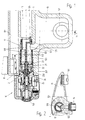
- FIGs 1 and 2 of the drawing is one in part Sanitary water fitting or water mixer shown shown.
- the fitting consists of a fitting body 1, with an inlet 10 to the hot water supply line network and with another Connection - not shown in the drawing - to the Cold water supply network is connected.
- a water mixing valve especially a thermostatically controlled one Mixing valve, as it is from the European patent specification EP 0 242 680 B1 is known.
- the Water inlet 10 for hot water is here via a Hot water channel 101 connected to the mixing valve.
- the part of the valve body not shown in the drawing 1 is another water inlet for cold water trained and also with the mixing valve connected.
- the mixed water generated with the mixing valve is in a mixed water chamber 11 of the valve body 1 submitted.
- a mixed water channel 120 Downstream behind the mixed water chamber 11 is in the valve body 1 with an O-ring 123 sealed insert 12 arranged.
- three channels are arranged in parallel next to each other, namely a mixed water channel 120, an outlet channel 121 for a bathtub spout 13 and an outlet channel 122 to a shower connection 14.
- a shower connection 14 can be, for example, a hose line for a hand shower.
- the bathtub spout 13 is cantilevered on the valve body 1 trained and carries an outlet mouthpiece 131 for the Water leakage.
- the insert 12 On the downstream end the insert 12 is a changeover and flow control valve arranged in the form of a structural unit 2. This Valve can be operated with a rotary handle 15.
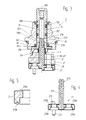
- the switching and flow control valve designed as unit 2 is in Figure 3 on an enlarged scale shown.
- the unit 2 is one non-rotatable, on a floor 27 held disc 21 Ceramic material and one attached to the disk 21, with the help of a spindle 25 and a driver 250 rotatably supported disc 22, also made of ceramic material, educated.
- the spindle 25 is in one piece with the driver 250 made of plastic and sealed in a head piece 26 with O-rings 251 stored.
- the spindle 25 is axially in the area of the driver 250 with a sliding washer 253 on one end face the head piece 26 supported.
- the driver 250 has three approximately symmetrical arranged projections 254, which in recesses 290 the disc 22 surround.
- the rotatable disc 21 on the other hand has two recesses which are approximately opposite one another 29, in the two axially opposite Grip projections 272 of the base 27. At the head start 272 opposite end faces the bottom 27 also two projections 273 with which the Floor 27 in the plug-in position in the valve body 1 non-rotatable in corresponding holes in the insert 12 borders.
- the insert 12 faces the opposite Front on a pin 124 with which he in a corresponding mounting hole of the valve body 1 borders and is thus also held in a rotationally fixed manner.
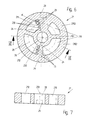
- the disk 21 held in a rotationally fixed manner has a circular shape and has in the right half a passage opening 210 in the form of a circular ring, which is provided with a web 2101 for stabilizing the outer edge 2102 of the disk 21 in the region of the passage opening 210 .
- the passage opening 210 is divided by the web 2101 according to the required flow rate to about a third for the shower connection 14 and about two thirds for the bathtub spout 13.
- a circular opening 211 for a shower connection is formed in the upper region and a circular opening 212 for a bath connection in the lower region.
- the three passage openings 210, 211, 212 are arranged on a bolt circle 20 of approximately 15 mm in diameter.
- the two passage openings 211 and 212 are provided on the end face facing the passage opening 210 with three teeth 23 arranged in a row on a radius 24 of the disk 21, which protrude into the passage openings 211 and 212.
- the three teeth 23 are arranged symmetrically on the end face, so that four tooth gaps 230 are formed in each passage opening.
- the teeth 23 protrude from the radius 24 by approximately 1.2 mm into the passage opening 211, 212, the teeth 23 having a flank angle ⁇ of approximately 12 °.
- a bore 28 is formed in the center of the disk 21 for the passage of a pin 271 of the base 27.
- the rotatable disk 22 attached to the disk 21 is likewise circular, as can be seen from the drawing in FIG. 8, and is kept somewhat smaller in diameter than the disk 21.
- approximately circular cutout-shaped through openings 221, 222 are formed approximately symmetrically in the right half.
- the passage opening 222 cooperates with the passage opening 211 in the pane 21, while the passage opening 221, on the other hand, cooperates with the passage opening 212 of the pane 21.
- the disc 22 has three approximately symmetrically arranged recesses 290 for the driver 250 and a bore 28 for the passage of the pin 271 of the base 27.
- the end faces of the passage openings 221, 222 facing the passage openings 211, 212 are arranged at an angle 223 of 5 to 10 °, preferably 6 °, inclined to the radius.
- the two disks made of ceramic material lie against one another with a smoothed sealing surface, so that a watertight shut-off of the passage openings 211 and 212 is ensured.
- the base 27 extends through the two disks 21, 22 in the bore 28 with the pin 271, on the projecting end of which resilient tongues 2711 are formed.
- a blind bore 251 is formed in the spindle 25, which forms a shoulder 2501.
- the pin 271 can be inserted into this blind hole 251, so that the resilient tongues 2711 engage behind the shoulder 2501 and the base 27 is connected to the spindle 25.
- the resilient tongues 2711 are placed on the pin 271 so that the manufacturing tolerances of the individual parts can be axially compensated.
- the resilient tongues 2711 are arranged in the locking position directly on the shoulder 2501 in the right half of the figure, while they are located above the shoulder 2501 with play in the left half of the figure.
- a radial opening 2511 is provided in the spindle 25 above the shoulder 2501. By means of this radial opening 2511, the tongues 2711 can be deflected from their detent position when the assembly 2 is removed.
- a helical spring 3 is arranged concentrically to the pin 271 between the upper end face of the rotatable disk 22 and the lower end face of the driver 250, so that the disk 22 is pressed against the disk 21 with a minimum contact force.
- the base 27 carries molded seals 2700 around the corresponding base passage openings, as can be seen in particular from FIGS. 4 and 5. With these seals 2700, the through openings 210, 211, 212 of the pane 21 are connected in a sealed manner to the mixed water channel 120, the outlet channel 121 to the bathtub spout and the outlet channel 122 to the shower outlet.
- the exposed sanitary fitting described above can be installed in the following way: First, the bottom 27 is joined together with the disks 21, 22 and the coil spring 3. The spindle 25 is then connected to the completed base 27 by means of a snap connection 270, after which the three projections 254 engage in the recesses 290 and the coil spring 3 is preloaded accordingly. Now the head piece 26 with the sliding disk 253 can be pushed onto the spindle 25 and secured in the plug-in position with a snap ring 260 in the axial plug-in position. This completes assembly 2. The insert 12 with the O-rings 123 is first introduced into a receiving bore in the finished valve body 1.
- the assembly 2 can then be pushed into the front area of the receiving bore of the fitting body 1 and screwed tightly by means of thread 261 and an O-ring 262. Thereafter, the rotary handle 15 can be fastened to the spindle 25 with a fastening screw 150.
- the mixing valve described in EP 0 242 680 B1 can be installed in parallel.
- the exposed water tap described above works as follows:
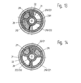
- the hot water and cold water supplied to the fitting body 1 by the two supply line networks are mixed to tempered water in the mixing valve (not shown in the drawing) and fed via the mixed water chamber 11 into the mixed water channel 120 of the insert. From here it passes through a passage opening in the floor 27 into the passage opening 210 of the disk 21 and from here through the passage openings 221 and 222 of the rotatable disk 22 into a pressure chamber 4 and presses the rotatable disk 22 together with the helical spring 3 against the non-rotatably on the floor 27 held disc 21. In the rotational position of the disks 21 and 22 shown in FIG. 10 with respect to one another, the passage openings 211 and 212 are blocked off.
- the passage opening 221 increasingly overlaps with the passage opening 211, as can be seen in particular from FIG.
- the outer tooth gap 230 of the passage opening 221 initially overlaps and subsequently the tooth gaps 230 located further inside, so that successive partial flows into the passage opening 211 for the shower connection 14 can pass sensitively and quietly.
- the entire cross section of the annular passage opening 211 is increasingly opened, so that in the end position, as shown in Figure 12, the full cross section of the passage opening 211 is released.
- the cross section of the passage opening 211 is designed to be smaller than the cross section of the passage opening 212.
- the passage opening 212 increasingly overlaps with the passage opening 222 in the same way, so that mixed water is increasingly supplied to the bathtub spout 13 as a function of the angle of rotation.
- FIG. 14 shows the pane position with the passage opening 222 fully open for the bathtub spout 13.
- valve of the invention for switching and Flow control arranged in a surface-mounted fitting.
- valve can also be used with concealed fittings for flow control of the mixed water and switching between two consumers become.
- cold or instead of mixed water Hot water or another medium can be used.
Landscapes
- Engineering & Computer Science (AREA)
- General Engineering & Computer Science (AREA)
- Mechanical Engineering (AREA)
- Multiple-Way Valves (AREA)
- Sliding Valves (AREA)
- Valve-Gear Or Valve Arrangements (AREA)
- Details Of Valves (AREA)
- Fluid-Driven Valves (AREA)
- Magnetically Actuated Valves (AREA)
- Compressor (AREA)
- Taps Or Cocks (AREA)
- Lift Valve (AREA)
Claims (16)
- Soupape, notamment pour installations sanitaires comportant un boítier présentant au moins une ouverture d'entrée (120) et au moins deux ouvertures de sortie (121, 122) et dans lequel un disque (21) ne pouvant tourner constitue un siège de soupape tandis qu'un disque (22) pouvant tourner sous l'action d'une tige de manoeuvre (25), est monté en tant que tiroir rotatif sur le disque non tournant, soupape dans laquelle,caractérisée en ce queles deux disques (21, 22) sont percés d'ouvertures de passage (210, 211, 212, 221, 222) qui permettent, dans chaque position du disque rotatif (22) le passage du fluide,par l'intermédiaire du disque rotatif (22) et en fonction de sa position de rotation, on peut libérer des ouvertures de passage pour la sortie du fluide,dans les deux disques (21, 22) les ouvertures de passage (210, 211, 212, 221, 222) du flux entrant et du flux sortant sont disposées sur un cercle des trous (20), concentrique à l'axe de rotation (200),le disque non tournant (21) présente, dans une de ses moitiés une ouverture de passage (210) pour le flux entrant et dans l'autre moitié, deux ouvertures de passage (211, 212) pour le flux sortant à destination de différents utilisateurs,dans le disque tournant (22) sont percées deux ouvertures de passage (221, 222) de manière que dans chaque position de rotation, le flux entrant peut passer à travers les deux disques (21, 22), et en partant d'une position de fermeture des deux ouvertures de passage (211, 212) du flux sortant, une rotation vers la gauche du disque tournant (22) libère progressivement la section d'une de ces deux ouvertures de passage ainsi qu'une liaison entre l'ouverture d'entrée (120) et une ouverture de sortie (122), tandis qu'une rotation vers la droite du disque tournant (22) libère progressivement la section de l'autre (212) de ces deux ouvertures de passage et ainsi également une liaison entre l'ouverture d'entrée (120) et l'autre ouverture de sortie (121).
- Soupape selon la revendication 1,
caractérisée en ce que
les ouvertures de passage (210, 211, 212, 221, 222) présentent au moins dans la zone des portées d'étanchéité des deux disques (21, 22) la forme d'un secteur d'anneau circulaire. - Soupape selon la revendication 2,
caractérisée en ce que
l'ouverture de passage (210) prévue pour le flux entrant est divisée, dans le disque non tournant (21) par une barrette (2101) qui a pour effet de stabiliser le bord externe (2102) du disque non tournant (21). - Soupape selon la revendication 3,
caractérisée en ce que
celle (211) des ouvertures de passage (211, 212) prévues pour le flux sortant est reliée à un raccord de douche (14) tandis que l'autre ouverture de passage (212) est reliée à un raccord de baignoire (13), la barrette (2101) divisant l'ouverture de passage (210), en forme de secteur d'anneau circulaire, destinée au flux entrant, en une ouverture plus petite, située dans la moitié du disque proche du raccord de douche (14), et en une ouverture plus grande, située dans la moitié du disque proche du raccord de baignoire (13). - Soupape selon la revendication 4,
caractérisée en ce que
l'ouverture de passage (210) prévue pour le flux entrant est divisée par la barrette (2101) en fonction du débit d'écoulement nécessaire, de préférence en un tiers environ pour le raccord de douche (14) et deux tiers environ pour le raccord de baignoire (13). - Soupape selon l'une quelconque des revendications 1 à 5,
caractérisée en ce que
dans les ouvertures de passage (211, 212) pour le flux sortant, sur le côté qui, lors de l'opération d'ouverture, vient le premier à être recouvert, il est prévu sur un ou sur les deux disques (21, 22) des dents (23) faisant saillie dans l'ouverture, de sorte qu'au début à l'ouverture et qu'à la fin à la fermeture le passage se trouve divisé en canaux individuels constitués par des entredents (230). - Soupape selon la revendication 6,
caractérisée en ce que
les dents (23) sont disposées sur les ouvertures de passage (211, 212) du flux sortant que présente le disque non tournant (21) et ont chacune leur pied sur le rayon (24) du disque (21), tandis que le côté des ouvertures de passage (221, 222) pratiquées dans le disque tournant (22) qui vient d'abord en liaison avec les dents (23) lors de l'ouverture, est incliné sur le rayon (24) d'un angle (223) de 5 à 10°, de préférence 6°, de sorte qu'à l'ouverture les entredents (230) en correspondance avec le sens de rotation, libèrent l'une après l'autre le passage. - Soupape selon la revendication 7,
caractérisée en ce qu'
avec un diamètre du cercle des trous (20) égal à 15 mm, les dents (23) ont une hauteur de 1 à 2 mm environ, de préférence 1, 2 mm. - Soupape selon la revendication 8,
caractérisée en ce que
trois dents (23) sont disposées en ligne sur le rayon (24) de sorte qu'il existe quatre entredents (230). - Soupape selon l'une quelconque des revendications 1 à 9,
caractérisée en ce que
les disques (21, 22), la tige (25), un entraíneur (250) et les éléments de pression et d'étanchéité comportant une pièce de tête (26) sont réunis en un ensemble constructif (2) qui peut être monté en bloc dans un corps de robinet (1). - Soupape selon la revendication 10,
caractérisée en ce qu'
au disque non tournant (21) est associé en rotation un fond (27) qui est garni d'une ou plusieurs saillies (273) qui pour maintenir la solidarité en rotation, sont embrochées dans des perçages correspondants du corps de robinet (1). - Soupape selon la revendication 11,
caractérisée en ce que
le fond (27) par l'intermédiaire d'une liaison par encliquetage (270) est relié à la tige de manoeuvre (25) pour pouvoir tourner, mais est fixé axialement. - Soupape selon la revendication 12,
caractérisée en ce que
sur le fond (27) est moulé un pivot (271) coaxial à l'axe de rotation (200), traversant en leurs centres les disques (21, 22) et portant, à son extrémité, des languettes élastiques (2711) qui, en position emmanchée, sont en prise derrière un épaulement (2501) de la tige de manoeuvre (25) et maintiennent l'ensemble constructif (2). - Soupape selon l'une quelconque des revendications 11 à 13,
caractérisée en ce que
le fond (27) est en matière plastique et les joints d'étanchéité nécessaires (2700) sont injectés dans le fond (27) sous la forme d'une pièce de coulée composite. - Soupape selon l'une quelconque des revendications 1 à 4,
caractérisée en ce que
la tige de manoeuvre (25) est fabriquée avec l'entraíneur (250) en une seule pièce de matière plastique. - Soupape selon la revendication 15,
caractérisée en ce que
la tige de manoeuvre (25) présente un trou borgne central (251) dans lequel est formé l'épaulement (2501) et au-dessus de l'épaulement (2501), la tige (25) présente un ou plusieurs passages radiaux (2511) de sorte que pour démonter l'ensemble (2), les languettes (2711) peuvent être déviées et quitter ainsi leur position d'arrêt.
Applications Claiming Priority (2)
| Application Number | Priority Date | Filing Date | Title |
|---|---|---|---|
| DE19614653A DE19614653A1 (de) | 1996-04-13 | 1996-04-13 | Ventil |
| DE19614653 | 1996-04-13 |
Publications (3)
| Publication Number | Publication Date |
|---|---|
| EP0801255A2 EP0801255A2 (fr) | 1997-10-15 |
| EP0801255A3 EP0801255A3 (fr) | 1998-03-25 |
| EP0801255B1 true EP0801255B1 (fr) | 2001-08-29 |
Family
ID=7791199
Family Applications (1)
| Application Number | Title | Priority Date | Filing Date |
|---|---|---|---|
| EP97105016A Expired - Lifetime EP0801255B1 (fr) | 1996-04-13 | 1997-03-25 | Tiroir rotative |
Country Status (11)
| Country | Link |
|---|---|
| US (1) | US5775373A (fr) |
| EP (1) | EP0801255B1 (fr) |
| JP (1) | JPH109417A (fr) |
| AT (1) | ATE204967T1 (fr) |
| CZ (1) | CZ97397A3 (fr) |
| DE (2) | DE19614653A1 (fr) |
| DK (1) | DK0801255T3 (fr) |
| ES (2) | ES2162145T3 (fr) |
| PL (1) | PL319424A1 (fr) |
| PT (1) | PT801255E (fr) |
| SK (1) | SK45697A3 (fr) |
Cited By (1)
| Publication number | Priority date | Publication date | Assignee | Title |
|---|---|---|---|---|
| EP2418409A1 (fr) | 2010-08-12 | 2012-02-15 | Grohe AG | Poignée tournante |
Families Citing this family (23)
| Publication number | Priority date | Publication date | Assignee | Title |
|---|---|---|---|---|
| AU1309099A (en) * | 1997-11-05 | 1999-05-24 | Amerikam, Inc. | Tub and shower diverter valve |
| DE19962169C2 (de) * | 1999-12-22 | 2002-05-23 | Steag Micro Tech Gmbh | Vorrichtung zum Behandeln von Substraten |
| IT1319941B1 (it) | 2000-03-07 | 2003-11-12 | Gevipi Ag | Dispositivo combinatore di erogazione per l'alimentazione diapparecchi idraulici. |
| DE10037470B4 (de) * | 2000-08-01 | 2006-09-07 | Hansgrohe Ag | Sanitärarmatur |
| RU2175735C1 (ru) * | 2001-01-25 | 2001-11-10 | Немытко Виктор Ефимович | Кран |
| DE10104280A1 (de) * | 2001-01-30 | 2002-08-01 | Kludi Armaturen Scheffer Vertr | Umstell-Ventil für eine sanitäre Armatur |
| DE10104888A1 (de) * | 2001-02-01 | 2002-08-08 | Kludi Armaturen Scheffer Vertr | Ventil für eine sanitäre Armatur |
| FR2827356B1 (fr) * | 2001-07-11 | 2004-11-05 | Valeo Thermique Moteur Sa | Vanne de commande a disques pour circuit de circulation fluide |
| DE10137611C1 (de) * | 2001-08-01 | 2003-04-30 | Hansa Metallwerke Ag | Umstellvorrichtung für eine Sanitäreinrichtung mit mindestens zwei Wasserverbrauchern |
| DE10161858A1 (de) | 2001-12-14 | 2003-06-26 | Grohe Armaturen Friedrich | Umschaltventil |
| DE10336127B4 (de) * | 2003-08-04 | 2009-10-08 | Grohe Ag | Mehrwegeventil |
| US20060016001A1 (en) * | 2004-07-26 | 2006-01-26 | Zhao Wei D | Ceramic diverter for tub spout |
| US7461669B2 (en) * | 2005-04-08 | 2008-12-09 | Masco Corporation Of Indiana | Seat keeper |
| DE102010018671A1 (de) | 2010-04-28 | 2011-11-03 | Grohe Ag | Sanitäre Mischbatterie, insbesondere für eine Brausevorrichtung |
| ES1075446Y (es) * | 2011-07-28 | 2012-01-13 | Caspro Sa | Valvula termostatica |
| CN105179724B (zh) * | 2015-07-22 | 2018-08-07 | 湖北省水利水电规划勘测设计院 | 一种超大型水库放空阀结构 |
| DE102015012523A1 (de) | 2015-09-26 | 2017-03-30 | Karl Schmitt | Apparatur zur Zwischenspeicherung und Nutzung des bei sanitären Warmwasserspendern anfänglich zu kaltem Mischwasser |
| US10856668B2 (en) | 2017-04-10 | 2020-12-08 | Hill-Rom Services, Inc. | Mattress overlay control system with rotary valves and graphical user interface for percussion and vibration, turn assist and microclimate management |
| US10959536B2 (en) * | 2017-10-17 | 2021-03-30 | Hill-Rom Services, Inc. | Selectable control valves and inflatable mattress systems comprising the same |
| GB2571560B (en) | 2018-03-01 | 2020-06-03 | Kohler Mira Ltd | Bar valve |
| JP2022013428A (ja) * | 2020-07-03 | 2022-01-18 | 株式会社デンソー | バルブ装置 |
| JP7322850B2 (ja) * | 2020-10-02 | 2023-08-08 | 株式会社デンソー | バルブ装置 |
| WO2025205361A1 (fr) * | 2024-03-26 | 2025-10-02 | 株式会社デンソー | Dispositif de valve |
Family Cites Families (8)
| Publication number | Priority date | Publication date | Assignee | Title |
|---|---|---|---|---|
| DE2841998C2 (de) * | 1978-09-27 | 1984-03-29 | H.D. Eichelberg & Co Gmbh, 5860 Iserlohn | Ventil für sanitäre Anlagen |
| EP0063627A1 (fr) * | 1981-04-28 | 1982-11-03 | Rosenthal Technik AG | Mitigeur |
| DE3612988A1 (de) * | 1986-04-17 | 1987-10-29 | Grohe Armaturen Friedrich | Mischbatterie |
| DE3638959A1 (de) * | 1986-11-14 | 1988-05-26 | Grohe Armaturen Friedrich | Umschaltventil |
| US4794952A (en) * | 1987-02-04 | 1989-01-03 | American Standard | Combination mixing valve and appliance valve assembly |
| DE3808899A1 (de) * | 1988-03-17 | 1989-09-28 | Voss Armaturen | Schaltventil |
| CA1319080C (fr) * | 1988-12-20 | 1993-06-15 | Pietro Rollini | Ensemble de robinetterie pour equipements sanitaires |
| DE4035838A1 (de) * | 1990-11-10 | 1992-07-23 | Grohe Armaturen Friedrich | Wasserventil fuer sanitaere anlagen |
-
1996
- 1996-04-13 DE DE19614653A patent/DE19614653A1/de not_active Withdrawn
-
1997
- 1997-03-25 DE DE59704413T patent/DE59704413D1/de not_active Expired - Lifetime
- 1997-03-25 DK DK97105016T patent/DK0801255T3/da active
- 1997-03-25 AT AT97105016T patent/ATE204967T1/de not_active IP Right Cessation
- 1997-03-25 PT PT97105016T patent/PT801255E/pt unknown
- 1997-03-25 EP EP97105016A patent/EP0801255B1/fr not_active Expired - Lifetime
- 1997-03-25 ES ES97105016T patent/ES2162145T3/es not_active Expired - Lifetime
- 1997-03-25 US US08/823,640 patent/US5775373A/en not_active Expired - Fee Related
- 1997-03-28 CZ CZ97973A patent/CZ97397A3/cs unknown
- 1997-03-31 JP JP9079365A patent/JPH109417A/ja active Pending
- 1997-04-09 SK SK456-97A patent/SK45697A3/sk unknown
- 1997-04-10 ES ES09700928U patent/ES1036892Y/es not_active Expired - Fee Related
- 1997-04-10 PL PL97319424A patent/PL319424A1/xx unknown
Cited By (1)
| Publication number | Priority date | Publication date | Assignee | Title |
|---|---|---|---|---|
| EP2418409A1 (fr) | 2010-08-12 | 2012-02-15 | Grohe AG | Poignée tournante |
Also Published As
| Publication number | Publication date |
|---|---|
| PT801255E (pt) | 2002-01-30 |
| ATE204967T1 (de) | 2001-09-15 |
| ES1036892Y (es) | 1998-04-01 |
| EP0801255A2 (fr) | 1997-10-15 |
| SK45697A3 (en) | 1997-11-05 |
| ES2162145T3 (es) | 2001-12-16 |
| DE59704413D1 (de) | 2001-10-04 |
| US5775373A (en) | 1998-07-07 |
| EP0801255A3 (fr) | 1998-03-25 |
| PL319424A1 (en) | 1997-10-27 |
| JPH109417A (ja) | 1998-01-13 |
| ES1036892U (es) | 1997-11-16 |
| CZ97397A3 (en) | 1997-10-15 |
| DE19614653A1 (de) | 1997-10-16 |
| DK0801255T3 (da) | 2001-12-17 |
Similar Documents
| Publication | Publication Date | Title |
|---|---|---|
| EP0801255B1 (fr) | Tiroir rotative | |
| EP0844423B1 (fr) | Mitigeur à monocommande. | |
| EP0485841B1 (fr) | Robinet sanitaire | |
| EP0382040B1 (fr) | Soupape de mélange sanitaire | |
| DE3690279C2 (de) | Schieberventil | |
| DE10133041A1 (de) | Wasserarmatur | |
| DE202021100840U1 (de) | Sanitärventil | |
| DE2349772A1 (de) | Absperrorgan | |
| DE2841998A1 (de) | Ventil fuer sanitaere anlagen | |
| EP0653581B1 (fr) | Robinet mitigeur et d'arrêt | |
| DE3013651A1 (de) | Mischbatterie | |
| DE10138304A1 (de) | Einhebelventil | |
| DE3500966A1 (de) | Einhandmischhahn | |
| EP1061299A2 (fr) | Soupape d'inverseur | |
| DE19507195C2 (de) | Einhebelmischbatterie für den Betrieb mit Überlauf-Warmwasserspeicher | |
| DE3113653A1 (de) | Mischbatterie | |
| CH574067A5 (en) | Water mixer tap for sinks etc - has fixed and rotable overlying ceramic plates with control apertures | |
| DE3518698A1 (de) | Einhandmischventil | |
| DE3239925C2 (fr) | ||
| DE19824399C2 (de) | Einhebelmischbatterie für den Betrieb mit Überlauf-Warmwasserspeicher | |
| DE3426480A1 (de) | Sicherheitsmischventil | |
| DE10133035A1 (de) | Wasseramatur | |
| EP0856693B1 (fr) | Robinet d'eau sanitaire | |
| EP1647747B1 (fr) | Robinet mitigeur | |
| EP0949437B1 (fr) | Joint d'étanchéité et tête de robinet comportant un tel joint |
Legal Events
| Date | Code | Title | Description |
|---|---|---|---|
| PUAI | Public reference made under article 153(3) epc to a published international application that has entered the european phase |
Free format text: ORIGINAL CODE: 0009012 |
|
| AK | Designated contracting states |
Kind code of ref document: A2 Designated state(s): AT BE CH DE DK ES FI FR GB IT LI NL PT SE |
|
| PUAL | Search report despatched |
Free format text: ORIGINAL CODE: 0009013 |
|
| AK | Designated contracting states |
Kind code of ref document: A3 Designated state(s): AT BE CH DE DK ES FI FR GB IT LI NL PT SE |
|
| 17P | Request for examination filed |
Effective date: 19980610 |
|
| 17Q | First examination report despatched |
Effective date: 20000225 |
|
| RAP1 | Party data changed (applicant data changed or rights of an application transferred) |
Owner name: FRIEDRICH GROHE AG & CO. KG |
|
| GRAG | Despatch of communication of intention to grant |
Free format text: ORIGINAL CODE: EPIDOS AGRA |
|
| GRAG | Despatch of communication of intention to grant |
Free format text: ORIGINAL CODE: EPIDOS AGRA |
|
| GRAG | Despatch of communication of intention to grant |
Free format text: ORIGINAL CODE: EPIDOS AGRA |
|
| GRAH | Despatch of communication of intention to grant a patent |
Free format text: ORIGINAL CODE: EPIDOS IGRA |
|
| GRAH | Despatch of communication of intention to grant a patent |
Free format text: ORIGINAL CODE: EPIDOS IGRA |
|
| GRAA | (expected) grant |
Free format text: ORIGINAL CODE: 0009210 |
|
| AK | Designated contracting states |
Kind code of ref document: B1 Designated state(s): AT BE CH DE DK ES FI FR GB IT LI NL PT SE |
|
| REF | Corresponds to: |
Ref document number: 204967 Country of ref document: AT Date of ref document: 20010915 Kind code of ref document: T |
|
| REG | Reference to a national code |
Ref country code: CH Ref legal event code: NV Representative=s name: BOVARD AG PATENTANWAELTE Ref country code: CH Ref legal event code: EP |
|
| REF | Corresponds to: |
Ref document number: 59704413 Country of ref document: DE Date of ref document: 20011004 |
|
| ET | Fr: translation filed | ||
| GBT | Gb: translation of ep patent filed (gb section 77(6)(a)/1977) |
Effective date: 20011117 |
|
| REG | Reference to a national code |
Ref country code: ES Ref legal event code: FG2A Ref document number: 2162145 Country of ref document: ES Kind code of ref document: T3 |
|
| REG | Reference to a national code |
Ref country code: GB Ref legal event code: IF02 |
|
| REG | Reference to a national code |
Ref country code: PT Ref legal event code: SC4A Free format text: AVAILABILITY OF NATIONAL TRANSLATION Effective date: 20011018 |
|
| PLBQ | Unpublished change to opponent data |
Free format text: ORIGINAL CODE: EPIDOS OPPO |
|
| PLBI | Opposition filed |
Free format text: ORIGINAL CODE: 0009260 |
|
| PLBF | Reply of patent proprietor to notice(s) of opposition |
Free format text: ORIGINAL CODE: EPIDOS OBSO |
|
| 26 | Opposition filed |
Opponent name: HANSA METALLWERKE AG Effective date: 20020527 |
|
| NLR1 | Nl: opposition has been filed with the epo |
Opponent name: HANSA METALLWERKE AG |
|
| PLBF | Reply of patent proprietor to notice(s) of opposition |
Free format text: ORIGINAL CODE: EPIDOS OBSO |
|
| PGFP | Annual fee paid to national office [announced via postgrant information from national office to epo] |
Ref country code: SE Payment date: 20030225 Year of fee payment: 7 |
|
| PGFP | Annual fee paid to national office [announced via postgrant information from national office to epo] |
Ref country code: BE Payment date: 20030305 Year of fee payment: 7 |
|
| PGFP | Annual fee paid to national office [announced via postgrant information from national office to epo] |
Ref country code: FI Payment date: 20030306 Year of fee payment: 7 |
|
| PGFP | Annual fee paid to national office [announced via postgrant information from national office to epo] |
Ref country code: CH Payment date: 20030312 Year of fee payment: 7 |
|
| PGFP | Annual fee paid to national office [announced via postgrant information from national office to epo] |
Ref country code: DK Payment date: 20030318 Year of fee payment: 7 |
|
| PGFP | Annual fee paid to national office [announced via postgrant information from national office to epo] |
Ref country code: GB Payment date: 20030319 Year of fee payment: 7 |
|
| PGFP | Annual fee paid to national office [announced via postgrant information from national office to epo] |
Ref country code: AT Payment date: 20030327 Year of fee payment: 7 |
|
| PGFP | Annual fee paid to national office [announced via postgrant information from national office to epo] |
Ref country code: PT Payment date: 20030424 Year of fee payment: 7 |
|
| RAP2 | Party data changed (patent owner data changed or rights of a patent transferred) |
Owner name: GROHE WATER TECHNOLOGY AG & CO. KG |
|
| PLCK | Communication despatched that opposition was rejected |
Free format text: ORIGINAL CODE: EPIDOSNREJ1 |
|
| NLT2 | Nl: modifications (of names), taken from the european patent patent bulletin |
Owner name: GROHE WATER TECHNOLOGY AG & CO. KG |
|
| PG25 | Lapsed in a contracting state [announced via postgrant information from national office to epo] |
Ref country code: GB Free format text: LAPSE BECAUSE OF NON-PAYMENT OF DUE FEES Effective date: 20040325 Ref country code: FI Free format text: LAPSE BECAUSE OF NON-PAYMENT OF DUE FEES Effective date: 20040325 Ref country code: AT Free format text: LAPSE BECAUSE OF NON-PAYMENT OF DUE FEES Effective date: 20040325 |
|
| PG25 | Lapsed in a contracting state [announced via postgrant information from national office to epo] |
Ref country code: SE Free format text: LAPSE BECAUSE OF NON-PAYMENT OF DUE FEES Effective date: 20040326 |
|
| PLBN | Opposition rejected |
Free format text: ORIGINAL CODE: 0009273 |
|
| STAA | Information on the status of an ep patent application or granted ep patent |
Free format text: STATUS: OPPOSITION REJECTED |
|
| PG25 | Lapsed in a contracting state [announced via postgrant information from national office to epo] |
Ref country code: LI Free format text: LAPSE BECAUSE OF NON-PAYMENT OF DUE FEES Effective date: 20040331 Ref country code: DK Free format text: LAPSE BECAUSE OF NON-PAYMENT OF DUE FEES Effective date: 20040331 Ref country code: CH Free format text: LAPSE BECAUSE OF NON-PAYMENT OF DUE FEES Effective date: 20040331 Ref country code: BE Free format text: LAPSE BECAUSE OF NON-PAYMENT OF DUE FEES Effective date: 20040331 |
|
| 27O | Opposition rejected |
Effective date: 20031029 |
|
| NLR2 | Nl: decision of opposition |
Effective date: 20031029 |
|
| BERE | Be: lapsed |
Owner name: FRIEDRICH *GROHE A.G. & CO. K.G. Effective date: 20040331 |
|
| PG25 | Lapsed in a contracting state [announced via postgrant information from national office to epo] |
Ref country code: PT Free format text: LAPSE BECAUSE OF NON-PAYMENT OF DUE FEES Effective date: 20041015 |
|
| EUG | Se: european patent has lapsed | ||
| REG | Reference to a national code |
Ref country code: CH Ref legal event code: PL |
|
| GBPC | Gb: european patent ceased through non-payment of renewal fee |
Effective date: 20040325 |
|
| REG | Reference to a national code |
Ref country code: PT Ref legal event code: MM4A Free format text: LAPSE DUE TO NON-PAYMENT OF FEES Effective date: 20040930 |
|
| PGFP | Annual fee paid to national office [announced via postgrant information from national office to epo] |
Ref country code: IT Payment date: 20120329 Year of fee payment: 16 |
|
| PGFP | Annual fee paid to national office [announced via postgrant information from national office to epo] |
Ref country code: FR Payment date: 20130408 Year of fee payment: 17 Ref country code: ES Payment date: 20130326 Year of fee payment: 17 |
|
| PGFP | Annual fee paid to national office [announced via postgrant information from national office to epo] |
Ref country code: NL Payment date: 20130320 Year of fee payment: 17 |
|
| REG | Reference to a national code |
Ref country code: NL Ref legal event code: V1 Effective date: 20141001 |
|
| REG | Reference to a national code |
Ref country code: FR Ref legal event code: ST Effective date: 20141128 |
|
| PG25 | Lapsed in a contracting state [announced via postgrant information from national office to epo] |
Ref country code: FR Free format text: LAPSE BECAUSE OF NON-PAYMENT OF DUE FEES Effective date: 20140331 |
|
| PG25 | Lapsed in a contracting state [announced via postgrant information from national office to epo] |
Ref country code: NL Free format text: LAPSE BECAUSE OF NON-PAYMENT OF DUE FEES Effective date: 20141001 |
|
| PG25 | Lapsed in a contracting state [announced via postgrant information from national office to epo] |
Ref country code: IT Free format text: LAPSE BECAUSE OF NON-PAYMENT OF DUE FEES Effective date: 20140325 |
|
| REG | Reference to a national code |
Ref country code: ES Ref legal event code: FD2A Effective date: 20150427 |
|
| PGFP | Annual fee paid to national office [announced via postgrant information from national office to epo] |
Ref country code: DE Payment date: 20150320 Year of fee payment: 19 |
|
| PG25 | Lapsed in a contracting state [announced via postgrant information from national office to epo] |
Ref country code: ES Free format text: LAPSE BECAUSE OF NON-PAYMENT OF DUE FEES Effective date: 20140326 |
|
| REG | Reference to a national code |
Ref country code: DE Ref legal event code: R119 Ref document number: 59704413 Country of ref document: DE |
|
| PG25 | Lapsed in a contracting state [announced via postgrant information from national office to epo] |
Ref country code: DE Free format text: LAPSE BECAUSE OF NON-PAYMENT OF DUE FEES Effective date: 20161001 |