EP0802152A2 - Cable guide for a winch - Google Patents
Cable guide for a winch Download PDFInfo
- Publication number
- EP0802152A2 EP0802152A2 EP97250121A EP97250121A EP0802152A2 EP 0802152 A2 EP0802152 A2 EP 0802152A2 EP 97250121 A EP97250121 A EP 97250121A EP 97250121 A EP97250121 A EP 97250121A EP 0802152 A2 EP0802152 A2 EP 0802152A2
- Authority
- EP
- European Patent Office
- Prior art keywords
- rail
- coupling
- rope
- tracks
- longitudinal
- Prior art date
- Legal status (The legal status is an assumption and is not a legal conclusion. Google has not performed a legal analysis and makes no representation as to the accuracy of the status listed.)
- Granted
Links
Images


Classifications
-
- B—PERFORMING OPERATIONS; TRANSPORTING
- B66—HOISTING; LIFTING; HAULING
- B66D—CAPSTANS; WINCHES; TACKLES, e.g. PULLEY BLOCKS; HOISTS
- B66D1/00—Rope, cable, or chain winding mechanisms; Capstans
- B66D1/28—Other constructional details
- B66D1/36—Guiding, or otherwise ensuring winding in an orderly manner, of ropes, cables, or chains
- B66D1/38—Guiding, or otherwise ensuring winding in an orderly manner, of ropes, cables, or chains by means of guides movable relative to drum or barrel
-
- B—PERFORMING OPERATIONS; TRANSPORTING
- B66—HOISTING; LIFTING; HAULING
- B66D—CAPSTANS; WINCHES; TACKLES, e.g. PULLEY BLOCKS; HOISTS
- B66D1/00—Rope, cable, or chain winding mechanisms; Capstans
- B66D1/28—Other constructional details
- B66D1/36—Guiding, or otherwise ensuring winding in an orderly manner, of ropes, cables, or chains
-
- B—PERFORMING OPERATIONS; TRANSPORTING
- B66—HOISTING; LIFTING; HAULING
- B66D—CAPSTANS; WINCHES; TACKLES, e.g. PULLEY BLOCKS; HOISTS
- B66D2700/00—Capstans, winches or hoists
- B66D2700/01—Winches, capstans or pivots
- B66D2700/0183—Details, e.g. winch drums, cooling, bearings, mounting, base structures, cable guiding or attachment of the cable to the drum
- B66D2700/0191—Cable guiding during winding or paying out
Definitions
- the invention relates to a cable guide for a winch, in particular a hoist, with a winch drum having opposite rope grooves and rotatably mounted in a frame, with movable on at least one rail parallel to the axis of rotation of the winch drum and for aligning at least one pair of rope strands with respect to the assigned rope groove provided guide elements which are connected in opposite directions to one another via coupling means and can be driven by the windable or unwindable cable strands, the rail having at least two tracks which extend in the longitudinal direction of the rail and are arranged one behind the other in the direction of the cable strands and in which the guide elements are each guided and supported.
- Rope guides of this type are used on windmills which in particular have winch drums with rope grooves in order to prevent the permissible lateral deflection of the hoisting ropes from being exceeded along the axis of rotation of the winch drum; Such distractions occur, for example, by swinging the load or pulling at an angle. Experience has shown that a reduction in the resulting distractions leads to an increase in the lay-on time of the ropes.
- a generic cable guide in which a rail including the guide elements is pivotally suspended from the winch drum in the immediate vicinity of the tangential run-off points of the cable strands, which largely adjusts the pivoting movement of the rail including the guide elements to the deflection movement of the Rope strands transverse to the axis of rotation of the winch drum and a particularly gentle drive-free guidance of the rope strands enables.
- the rail has two tracks, one above the other, spaced apart and designed as laterally open channels for guiding one guide element each, the tracks being provided with grooves running in the longitudinal direction of the rail for slide rails guided therein.
- the invention has for its object to provide a drive-free cable guide for a windmill, in particular a hoist, which enables a gentle winding or unwinding of the rope, especially when the rope is inclined, but at the same time has a very compact design and still is very maintenance-free.
- the guide elements should be able to move over the entire length of the rail.
- the coupling means comprise coupling longitudinal beams which can be moved in opposite directions to one another in the longitudinal direction of the rails, each of which is guided in one of the tracks and is supported along the track at at least two spaced points, each coupling longitudinal beam being rigidly connected to one of the guide elements.
- Each coupling longitudinal member is rigidly connected to exactly one guide element and forms with it a unit which can be moved in the longitudinal direction of the rail and is supported at at least four points, the spacing of the support points being able to be chosen to be relatively large.
- the rigidly connected unit comprising the longitudinal coupling member and the guide element is guided and supported in various tracks via the guide element, the support and guidance of the Unit is significantly strengthened via the coupling side member.
- the spacing of the support points of the coupling longitudinal member can be chosen to be relatively large, so that, in particular, there is excellent horizontal stabilization of the guide element, which effectively prevents the guide element from jamming even with large rope forces.
- the rope guide according to the invention can be implemented in a very compact design. In particular, the design according to the invention makes it possible to move the guide elements over the entire length of the rail.
- the coupling longitudinal members are designed as toothed racks into which a gearwheel which rotates freely in the rail and connects the coupling longitudinal members engages.
- a gearwheel which rotates freely in the rail and connects the coupling longitudinal members engages.
- the pins of the gearwheel can be inserted with play into an opening provided in the rail, which makes it possible to fix the coupling longitudinal members arranged in the tracks in almost any position relative to one another, and in fact without any adjustment effort.
- Each coupling longitudinal member is expediently supported in the track in the region of the coupling longitudinal member ends via horizontally freely rotatable wheels.
- the possible large distance between the impellers ensures very good horizontal stabilization of the guide element; the use of rollers ensures smooth running of the guide element.
- each coupling longitudinal member is guided in the track via at least one vertically freely rotatable support roller to improve the guidance and support of the guide element on the coupling longitudinal member end facing away from the guide element.
- each guide element is supported in the tracks arranged one behind the other as seen in the direction of the cable strands by means of two support rollers arranged on the guide element.
- the traces advantageously form support surfaces themselves in the cross-sectional base and / or on the side surfaces.
- tracks with holding elements which form vertically arranged support surfaces and / or running surfaces running in the longitudinal direction of the rail and horizontally arranged supporting surfaces and / or running surfaces running in the longitudinal direction of the rail. These ensure perfect guidance and support of the guide element within the rail.
- a particularly dirt-resistant construction of the cable guide is ensured in that the running wheels and the support rollers are at least partially replaced by sliding elements.
- Fig. 1 shows a rail of a cable guide of a hoist, which has a winch drum, not shown, rotatably mounted in a frame, in the Opposing rope grooves are formed on the surface.
- the rail 1 has two tracks 2a, 2b, which extend in the longitudinal direction of the rail and are arranged parallel to one another in the direction of the cable strands, which are designed as spaced and laterally open channels and serve to guide two guide elements 3, the tracks 2a, 2b being guided through a web 4 are connected to each other.
- the guide elements 3 serve to align a pair of rope strands in relation to the assigned rope groove and can be moved in the longitudinal direction of the rail 1 parallel to the axis of rotation of the winch drum and are driven by the rope strands that can be wound or unwound.
- the guide elements 3 each have a support roller 5a, 5b with a vertical axis of rotation which is freely rotatable at the top and bottom and which are supported in the tracks 2a, 2b arranged one behind the other in the direction of the cable strands.
- a cable guide channel carrier 6 is fastened to the guide element 3 with a trained cable guide channel.
- the two guide elements 3 are each rigidly connected to a longitudinal coupling member 7a, 7b, the longitudinal coupling member 7a 7b being designed as toothed racks with teeth pointing towards the middle of the rail.
- the two longitudinal coupling members 7a, 7b are connected to one another via a gear wheel 8 which is freely rotatably mounted in the rail 1, the pins 10 (FIG. 3) of which are rotatably mounted in the rail.
- the pins 9 of the gearwheel 8 with radial play 9a are inserted into openings provided for this purpose; the gear wheel can be inserted in almost any position of the coupling longitudinal members 7a, 7b arranged in the tracks relative to one another.
- the guide elements 3a, 3b are connected to one another in opposite directions via the gearwheel 8 engaging in the teeth of the toothed racks of the coupling longitudinal members 7a, 7b.
- Each longitudinal coupling member 7a, 7b is supported at the ends by horizontally freely rotatable wheels 10a, 10b in the track 2a or 2b, that is, at two widely spaced points.
- each coupling longitudinal member 7a, 7b is movably guided and supported on the guide element 3a or 3b via a support roller 11a or 11b which is freely rotatably mounted vertically in the track 2a or 2b in the longitudinal direction of the rail.
- FIG. 2 shows a cross section according to section line A-A according to FIG. 1.
- the tracks 2a, 2b form support surfaces 12, 13 in the cross-sectional base and support surfaces 14 on the side surfaces.
- the tracks 2a, 2b are provided with holding elements which form vertically arranged support surfaces 18, 19 and horizontally arranged running surfaces 20, all of which run in the longitudinal direction of the rails. All the wheels 10a, 10b and all the support rollers 5a, 5b, 11a, 11b are both supported and guided by the support surfaces 12, 13, 14, 18, 19, 20. 2, the web 4, which connects the two tracks 2a, 2b, can be clearly seen.
- FIG. 3 shows the cross section of the rail 1 in the region of the gear 8; 3, in particular, the interaction of the gearwheel 8 with the coupling longitudinal members 7a, 7b, which are designed as toothed racks, can be removed.
- the teeth 22 of the gear 8 engage at the top and bottom of the rack of the coupling longitudinal member 7a and 7b, whereby the racks are fixed in their horizontal position to each other.
- a longitudinal section of the rail along the section line C - C according to FIG. 3 is shown in FIG. 4.
- Fig. 5 shows a cross section through the rail 1 according to the section line AA in Fig. 1 in an alternative embodiment, wherein all the wheels 10a, 10b and all the support rollers 5a, 5b, 11a, 11b are replaced by sliding elements 23 with a square cross-section ;.
- the guide elements 3a, 3b are guided and supported by means of the support surfaces 12, 13, 14, 18, 19, 20, the sliding elements 23 sliding along these support surfaces when the guide elements 3a, 3b move.
Landscapes
- Engineering & Computer Science (AREA)
- Mechanical Engineering (AREA)
- Types And Forms Of Lifts (AREA)
- Lift-Guide Devices, And Elevator Ropes And Cables (AREA)
- Movable Scaffolding (AREA)
- Carriers, Traveling Bodies, And Overhead Traveling Cranes (AREA)
- Transmission Devices (AREA)
- Emergency Lowering Means (AREA)
Abstract
Die Erfindung betrifft eine Seilführung für ein Windwerk, insbesondere ein Hubwerk, mit einer gegenläufige Seilrillen aufweisenden und in einem Rahmen drehgelagerten Windentrommel, mit an einer Schiene parallel zur Drehachse der Windentrommel verfahrbaren Führungselementen, die über Kopplungsmittel gegenläufig miteinander verbunden sind, wobei die Schiene zumindest zwei sich in Schienenlängsrichtung erstreckende und parallel zueinander in Richtung der Seilstränge gesehen hintereinander angeordnete Spuren aufweist, in denen die Führungselemente jeweils geführt und abgestützt sind. Um ein schonendes Auf- oder Abwickeln des Seiles, insbesondere auch bei Schrägzug, zu ermöglichen, bei gleichzeitig sehr kompakter Bauform und trotzdem großer Wartungsfreiheit; wird vorgeschlagen, daß die Kopplungsmittel in Schienenlängsrichtung gegenläufig zueinander bewegbare Kopplungslängsträger (7a, 7b) umfassen, die jeweils in einer der Spuren (2a, 2b) geführt und längs der Spur (2a, 2b) an zumindest zwei beabstandeten Punkten abgestützt sind und daß jeder Kopplungslängsträger (7a, 7b) mit einem der Führungselemente (3a bzw. 3b) starr verbunden ist.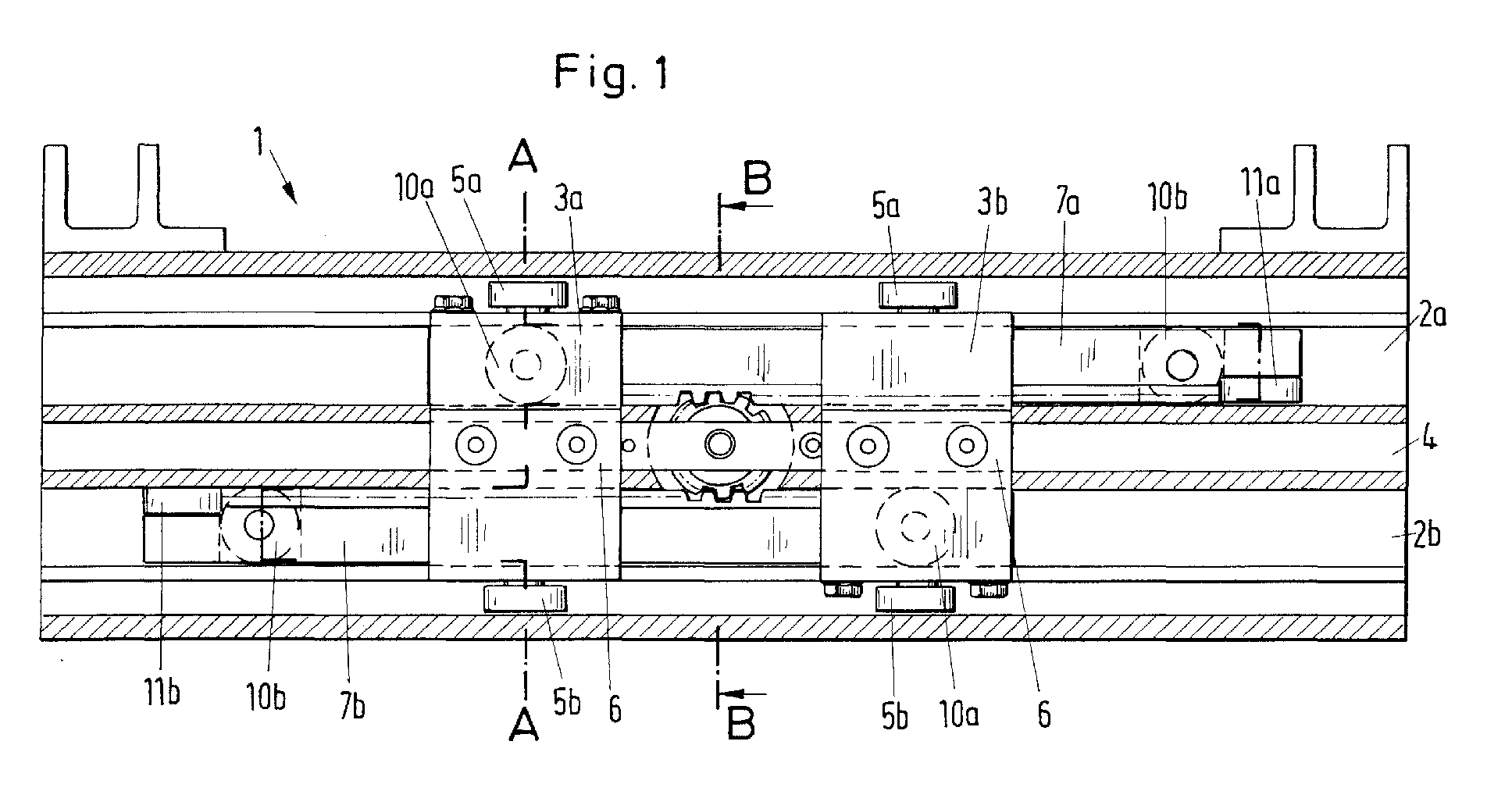
Description
Die Erfindung betrifft eine Seilführung für ein Windwerk, insbesondere ein Hubwerk, mit einer gegenläufige Seilrillen aufweisenden und in einem Rahmen drehgelagerten Windentrommel, mit an zumindest einer Schiene parallel zur Drehachse der Windentrommel verfahrbaren und zur Ausrichtung von zumindest einem Paar Seilstränge in bezug auf die zugeordnete Seilrille vorgesehenen Führungselementen, die über Kopplungsmittel gegenläufig miteinander verbunden und von den aufwickelbaren oder abwickelbaren Seilsträngen antreibbar sind wobei die Schiene zumindest zwei sich in Schienenlängsrichtung erstreckende und parallel zueinander in Richtung der Seilstränge gesehen hintereinander angeordnete Spuren aufweist, in denen die Führungselemente jeweils geführt und abgestützt sind.The invention relates to a cable guide for a winch, in particular a hoist, with a winch drum having opposite rope grooves and rotatably mounted in a frame, with movable on at least one rail parallel to the axis of rotation of the winch drum and for aligning at least one pair of rope strands with respect to the assigned rope groove provided guide elements which are connected in opposite directions to one another via coupling means and can be driven by the windable or unwindable cable strands, the rail having at least two tracks which extend in the longitudinal direction of the rail and are arranged one behind the other in the direction of the cable strands and in which the guide elements are each guided and supported.
Derartige Seilführungen werden an Windwerken eingesetzt, die insbesondere Windentrommeln mit Seilrillen aufweisen, um eine Überschreitung der zulässigen seitlichen Ablenkung der Hubseile längs zur Drehachse der Windentrommel zu verhindern; derartige Ablenkungen treten beispielsweise durch Pendeln der Last oder Schrägzug auf. Erfahrungsgemäß führt eine Verkleinerung der daraus resultierenden Ablenkungen zu einer Erhöhung der Aufliegezeit der Seile.Rope guides of this type are used on windmills which in particular have winch drums with rope grooves in order to prevent the permissible lateral deflection of the hoisting ropes from being exceeded along the axis of rotation of the winch drum; Such distractions occur, for example, by swinging the load or pulling at an angle. Experience has shown that a reduction in the resulting distractions leads to an increase in the lay-on time of the ropes.
Aus der DE 42 41 655 C1 ist eine gattungsgemäße Seilführung bekannt, bei der eine Schiene einschließlich der Führungselemente in unmittelbarer Nähe zu den tangentialen Ablaufpunkten der Seilstränge von der Windentrommel schwenkbar aufgehängt ist, was eine weitestgehende Anpassung der Schwenkbewegung der Schiene einschließlich der Führungselemente an die Auslenkbewegung der Seilstränge quer zur Drehachse der Windentrommel und eine besonders schonende antriebslose Führung der Seilstränge ermöglicht. Die Schiene weist zwei übereinander angeordnete voneinander beabstandete und als seitlich offene Kanäle ausgebildete Spuren zur Führung je eines Führungselementes auf, wobei die Spuren mit in Längsrichtung der Schiene verlaufenden Nuten für darin geführte Gleitleisten versehen sind. Aufgrund der zur stabilen Führung mit entsprechender Stützwirkung erforderlichen relativ großen Länge der Gleitleisten, durch welche die Kräfte über die Führungselemente auf die Schiene übertragen werden, ist eine kompakte Bauweise nur begrenzt möglich; die Führungselemente lassen sich bei dieser Seilführung insbesondere nicht über die gesamte Länge der Schiene bewegen.From DE 42 41 655 C1 a generic cable guide is known in which a rail including the guide elements is pivotally suspended from the winch drum in the immediate vicinity of the tangential run-off points of the cable strands, which largely adjusts the pivoting movement of the rail including the guide elements to the deflection movement of the Rope strands transverse to the axis of rotation of the winch drum and a particularly gentle drive-free guidance of the rope strands enables. The rail has two tracks, one above the other, spaced apart and designed as laterally open channels for guiding one guide element each, the tracks being provided with grooves running in the longitudinal direction of the rail for slide rails guided therein. Because of the relatively large length of the slide strips required for stable guidance with a corresponding support effect, through which the forces are transmitted to the rail via the guide elements, a compact design is only possible to a limited extent; the guide elements can not be moved over the entire length of the rail in particular with this rope guide.
Der Erfindung liegt die Aufgabe zugrunde, eine antriebslose Seilführung für ein Windwerk, insbesondere ein Hubwerk, zu schaffen, die ein schonendes Auf- oder Abwickeln des Seiles, insbesondere auch bei Schrägzug des Seiles, ermöglicht, gleichzeitig aber eine sehr kompakte Bauform aufweist und dabei trotzdem sehr wartungsfrel ist. Insbesondere sollten sich die Fuhrungselemente über die gesamte Länge der Schiene bewegen lassen.The invention has for its object to provide a drive-free cable guide for a windmill, in particular a hoist, which enables a gentle winding or unwinding of the rope, especially when the rope is inclined, but at the same time has a very compact design and still is very maintenance-free. In particular, the guide elements should be able to move over the entire length of the rail.
Die Lösung dieser Aufgabe ist erfindungsgemäß gekennzeichnet durch die im Patentanspruch 1 angegebenen Merkmale. Durch die kennzeichnenden Merkmale der Unteransprüche 2 bis 9 ist die Seilführung in vorteilhafter Weise weiter ausgestaltbar.The solution to this problem is characterized by the features specified in
Erfindungsgemäß umfassen die Kopplungsmittel in Schienenlängsrichtung gegenläufig zueinander bewegbare Kopplungslängsträger, die jeweils in einer der Spuren geführt und längs der Spur an zumindest zwei beabstandeten Punkten abgestützt sind, wobei jeder Kopplungslängsträger mit einem der Führungselemente starr verbunden ist. Jeweils ein Kopplungslängsträger ist also mit genau einem Führungselement starr verbunden und bildet mit diesem eine in Schienenlängsrichtung bewegbare Einheit, die an zumindest vier Punkten abgestützt ist, wobei die Beabstandung der Stützpunkte relativ groß gewählt werden kann. Die starr verbundene Einheit aus Kopplungslängsträger und Führungselement ist über das Führungselement in verschiedenen Spuren geführt und abgestützt, wobei die Abstützung und Führung der Einheit über den Kopplungslängsträger deutlich verstärkt wird. Die Beabstandung der Abstützpunkte des Kopplungslängsträgers kann dabei relativ groß gewählt werden, so daß insbesondere eine exzellente horizontale Stabilisierung des Führungselements erfolgt, die ein Verklemmen des Führungselements auch bei großen Seilkräften wirkungsvoll verhindert. Dabei ist die erfindungsgemäße Seilführung in sehr kompakter Bauweise ausführbar. Insbesondere ermöglicht es die erfindungsgemäße Bauweise, die Führungselemente über die gesamte Länge der Schiene zu bewegen.According to the invention, the coupling means comprise coupling longitudinal beams which can be moved in opposite directions to one another in the longitudinal direction of the rails, each of which is guided in one of the tracks and is supported along the track at at least two spaced points, each coupling longitudinal beam being rigidly connected to one of the guide elements. Each coupling longitudinal member is rigidly connected to exactly one guide element and forms with it a unit which can be moved in the longitudinal direction of the rail and is supported at at least four points, the spacing of the support points being able to be chosen to be relatively large. The rigidly connected unit comprising the longitudinal coupling member and the guide element is guided and supported in various tracks via the guide element, the support and guidance of the Unit is significantly strengthened via the coupling side member. The spacing of the support points of the coupling longitudinal member can be chosen to be relatively large, so that, in particular, there is excellent horizontal stabilization of the guide element, which effectively prevents the guide element from jamming even with large rope forces. The rope guide according to the invention can be implemented in a very compact design. In particular, the design according to the invention makes it possible to move the guide elements over the entire length of the rail.
Vorteilhafterweise sind die Kopplungslängsträger als Zahnstangen ausgebildet, in die ein in der Schiene frei drehbar gelagertes, die Kopplungslängsträger verbindendes Zahnrad eingreift. Auf diese Weise wird mit sehr einfachen Mitteln die gegenläufige Bewegung der Führungselemente sichergestellt.Advantageously, the coupling longitudinal members are designed as toothed racks into which a gearwheel which rotates freely in the rail and connects the coupling longitudinal members engages. In this way, the opposite movement of the guide elements is ensured with very simple means.
Dabei sind die Zapfen des Zahnrads mit Spiel in eine in der Schiene vorgesehene Öffnung einsetzbar, was die Fixierung der in den Spuren angeordneten Kopplungslängsträger bei nahezu jeder Lage relativ zueinander ermöglicht und zwar nahezu ohne Justageaufwand.The pins of the gearwheel can be inserted with play into an opening provided in the rail, which makes it possible to fix the coupling longitudinal members arranged in the tracks in almost any position relative to one another, and in fact without any adjustment effort.
Zweckmäßigerweise ist jeder Kopplungslängsträger jeweils im Bereich der Kopplungslängsträgerenden über horizontal frei drehbar gelagerte Laufräder in der Spur abgestützt. Der hierbei mögliche große Abstand der Laufräder sorgt dabei für eine sehr gute horizontale Stabilisierung des Führungselements; der Einsatz von Laufrollen stellt einen leichtgängigen Lauf des Führungselementes sicher.Each coupling longitudinal member is expediently supported in the track in the region of the coupling longitudinal member ends via horizontally freely rotatable wheels. The possible large distance between the impellers ensures very good horizontal stabilization of the guide element; the use of rollers ensures smooth running of the guide element.
Zusätzlich ist jeder Kopplungslängsträger zur Verbesserung der Führung und Abstützung des Führungselements an dem Führungselement abgewandten Kopplungslängsträgerende zumindest über eine vertikal frei drehbar gelagerte Stützrolle in der Spur geführt.In addition, each coupling longitudinal member is guided in the track via at least one vertically freely rotatable support roller to improve the guidance and support of the guide element on the coupling longitudinal member end facing away from the guide element.
Eine sehr gute Führung und Abstützung ergibt sich, wenn jedes Führungselement jeweils mittels zweier am Führungselement angeordneter Stützrollen in dem in Richtung der Seilstränge gesehen hintereinander angeordneten Spuren abgestützt ist.A very good guidance and support is obtained if each guide element is supported in the tracks arranged one behind the other as seen in the direction of the cable strands by means of two support rollers arranged on the guide element.
Vorteilhafterweise bilden die Spuren selbst im Querschnittsgrund und/oder an den Seitenflächen Stützflächen.The traces advantageously form support surfaces themselves in the cross-sectional base and / or on the side surfaces.
Zusätzlich ist es vorteilhaft, die Spuren mit Halteelemten zu versehen, die vertikal angeordnete, in Schienenlängsrichtung verlaufende Stützflächen und/oder Laufflächen und horizontal angeordnete in Schienenlängsrichtung verlaufende Stützflächen und/oder Laufflächen bilden. Diese gewährleisten eine einwandfreie Führung und Abstützung des Führungselements innerhalb der Schiene.In addition, it is advantageous to provide the tracks with holding elements which form vertically arranged support surfaces and / or running surfaces running in the longitudinal direction of the rail and horizontally arranged supporting surfaces and / or running surfaces running in the longitudinal direction of the rail. These ensure perfect guidance and support of the guide element within the rail.
Eine besonders schmutzunempfindliche Bauweise der Seilführung wird dadurch gewährleistet, daß die Laufräder und die Stützrollen zumindest teilweise durch Gleitelemente ersetzt sind.A particularly dirt-resistant construction of the cable guide is ensured in that the running wheels and the support rollers are at least partially replaced by sliding elements.
Ein Ausführungsbeispiel der Erfindung ist in der Zeichnung dargestellt und wird nachfolgend näher beschrieben. Es zeigen:
- Fig. 1
- eine Vorderansicht der Schiene mit zwei jeweils mit einer Zahnstange starr verbundenen Führungselementen,
- Fig. 2
- einen Querschnitt durch die Schiene gemäß der Schnittlinie A-A nach Fig. 1,
- Fig. 3
- einen Querschnitt durch die Schiene gemäß der Schnittlinie B-B nach Fig. 1,
- Fig. 4
- einen Längsschnitt der Schiene gemäß der Schnittlinie C-C nach Fig. 3 und
- Fig. 5
- einen Querschnitt durch die Schiene gemäß der Schnittlinie A-A nach Fig. 1 mit Gleitelementen.
- Fig. 1
- 2 shows a front view of the rail with two guide elements each rigidly connected to a toothed rack,
- Fig. 2
- 2 shows a cross section through the rail along the section line AA according to FIG. 1,
- Fig. 3
- 2 shows a cross section through the rail along the section line BB according to FIG. 1,
- Fig. 4
- a longitudinal section of the rail along the section line CC of FIG. 3 and
- Fig. 5
- a cross section through the rail along the section line AA of FIG. 1 with sliding elements.
Fig. 1 läßt eine Schiene einer Seilführung eines Hubwerkes erkennen, das eine nicht gezeigte in einem Rahmen drehgelagerte Windentrommel aufweist, in deren Oberfläche gegenläufige Seilrillen eingeformt sind. Die Schiene 1 verfügt über zwei sich in Schienenlängsrichtung erstreckende und parallel zueinander in Richtung der Seilstränge gesehen hintereinander angeordnete Spuren 2a, 2b, die als beabstandete und seitlich offene Kanäle ausgebildet sind und zur Führung von zwei Führungselementen 3 dienen, wobei die Spuren 2a, 2b durch einen Steg 4 miteinander verbunden sind. Die Führungselemente 3 dienen zur Ausrichtung von einem Paar Seilstränge bezogen auf die zugeordnete Seilrille und sind in Längsrichtung der Schiene 1 parallel zur Drehachse der Windentrommel verfahrbar und werden von den aufwickelbaren oder abwickelbaren Seilsträngen angetrieben. Hierzu besitzen die Führungselemente 3 jeweils eine oben und unten frei drehbar angeordnete Stützrolle 5a, 5b mit vertikaler Drehachse, die in den in Richtung der Seilstränge gesehen hintereinander angeordneten Spuren 2a, 2b abgestützt sind. Zur Führung des Seils selbst ist ein Seilführungskanalträger 6 mit einem ausgebildeten Seilführungskanal jeweils am Führungselement 3 befestigt. Die beiden Führungselemente 3 sind jeweils mit einem Kopplungslängsträger 7a, 7b starr verbunden, wobei die Kopplungslängsträger 7a 7b als Zahnstangen mit zur Schienenmitte weisenden Zähnen ausgebildet sind. Wie Fig. 1 erkennen läßt, sind die beiden Kopplungslängsträger 7a, 7b über ein in der Schiene 1 frei drehbar gelagertes Zahnrad 8 miteinander verbunden, deren Zapfen 10 (Fig. 3) in der Schiene drehbar gelagert sind. Hierzu sind die Zapfen 9 des Zahnrads 8 mit Radialspiel 9a in hierzu vorgesehene Öffnungen eingesetzt; das Einsetzen des Zahnrads kann bei nahezu jeder Lage der in den Spuren angeordneten Kopplungslängsträger 7a, 7b zueinander erfolgen. Über das in die Zähne der Zahnstangen der Kopplungslängsträger 7a, 7b eingreifende Zahnrad 8 sind die Führungselemente 3a, 3b gegenläufig miteinander verbunden.Fig. 1 shows a rail of a cable guide of a hoist, which has a winch drum, not shown, rotatably mounted in a frame, in the Opposing rope grooves are formed on the surface. The
Jeder Kopplungslängsträger 7a, 7b ist an den Enden über horizontal frei drehbar gelagerte Laufräder 10a, 10b in der Spur 2a bzw. 2b, also an zwei weit auseinanderliegenden Punkten, abgestützt. Zusätzlich ist jeder Kopplungslängsträger 7a, 7b an dem Führungselement 3a bzw. 3b über eine vertikal frei drehbar gelagerte Stützrolle 11a bzw. 11b in der Spur 2a bzw. 2b in Schienenlängsrichtung beweglich geführt und abgestützt. Selbstverständlich ist es auch möglich, die Stützrollen 5a, 5b der Führungselemente 3a, 3b und die Stützrollen 11a, 11b und die Laufräder 10a, 10b der Kopplungslängsträger 7a, 7b in getrennt ausgebildeten Spuren laufen zu lassen.Each
Fig. 2 zeigt einen Querschnitt gemäß Schnittlinie A-A nach Fig. 1. Im Querschnitt ist deutlich zu erkennen, daß die Spuren 2a, 2b im Querschnittsgrund Stützflächen 12, 13 und an den Seitenflächen Stützflächen 14 bilden. Zusätzlich sind die Spuren 2a, 2b mit Halteelementen versehen, die vertikal angeordnete Stützflächen 18, 19 und horizontal angeordnete Laufflächen 20 bilden, welche alle in Schienenlängsrichtung verlaufen. Dabei werden alle Laufräder 10a, 10b als auch alle Stützrollen 5a, 5b, 11a, 11b von den Stützflächen 12, 13, 14, 18, 19, 20 sowohl abgestützt als auch geführt. In Fig. 2 ist der Steg 4, der die beiden Spuren 2a, 2b verbindet, deutlich zu erkennen.FIG. 2 shows a cross section according to section line A-A according to FIG. 1. In cross section it can clearly be seen that the tracks 2a, 2b
Ein Querschnitt durch die Schiene gemäß der Schnittlinie B - B nach Fig. 1 ist in Fig. 3 dargestellt. Fig. 3 zeigt den Querschnitt der Schiene 1 im Bereich des Zahnrads 8; so ist in Fig. 3 insbesondere das Zusammenwirken des Zahnrads 8 mit den als Zahnstangen ausgebildeten Kopplungslängsträgern 7a, 7b entnehmbar Das Zahnrad 8 ist mit den Zapfen 9 der Drehachse frei drehbar mit Radialspiel 21 in eine in der Schiene 1 vorgesehene Bohrung eingesetzt. Die Zähne 22 des Zahnrads 8 greifen oben und unten jeweils in die Zahnstange des Kopplungslängsträgers 7a und 7b ein, wodurch die Zahnstangen in ihrer horizontalen Lage zueinander fixiert sind. Ein Längsschnitt der Schiene gemäß der Schnittlinie C - C nach Fig. 3 ist in Fig. 4 wiedergegeben.A cross section through the rail along the section line BB in FIG. 1 is shown in FIG. 3. Fig. 3 shows the cross section of the
Fig. 5 zeigt einen Querschnitt durch die Schiene 1 gemäß der Schnittlinie A - A nach Fig. 1 in einer alternativen Ausführungsform, wobei alle Laufräder 10a, 10b als auch alle Stützrollen 5a, 5b, 11a, 11b durch Gleitelemente 23 mit quadratischem Querschnitt ersetzt sind;. selbstverständlich ist es auch möglich, die Laufräder und Stützrollen nur teilweise durch Gleitelemente zu ersetzen. Auch bei dieser alternativen Ausführungsform werden die Führungselemente 3a, 3b mittels der Stützflächen 12, 13, 14, 18, 19, 20 geführt und abgestützt, wobei die Gleitelemente 23 bei Bewegung der Führungselemente 3a, 3b auf diesen Stützflächen entlanggleiten.Fig. 5 shows a cross section through the
- 11
- Schienerail
- 2a, 2b2a, 2b
- Spurtrack
- 33rd
- FührungselementGuide element
- 44th
- Stegweb
- 5a, 5b5a, 5b
- StützrolleSupport roller
- 66
- SeilführungskanalträgerCable guide channel carrier
- 7a, 7b7a, 7b
- KopplungslängsträgerCoupling side members
- 88th
- Zahnradgear
- 99
- ZapfenCones
- 9a9a
- RadialspielRadial clearance
- 10a, 10b10a, 10b
- LaufräderWheels
- 11a, 11b11a, 11b
- StützrolleSupport roller
- 12, 13, 1412, 13, 14
- StützflächeSupport surface
- 15, 16, 1715, 16, 17
- HalteelementeHolding elements
- 18, 19, 2018, 19, 20
- StützflächeSupport surface
- 2121
- KanalträgerChannel carrier
- 2222
- Zähneteeth
- 2323
- GleitelementSliding element
Claims (9)
dadurch gekennzeichnet,
daß die Kopplungsmittel in Schienenlängsrichtung gegenläufig zueinander bewegbare Kopplungslängsträger (7a, 7b) umfassen, die jeweils in einer der Spuren (2a, 2b) geführt und längs der Spur (2a, 2b) an zumindest zwei beabstandeten Punkten abgestützt sind und daß jeder Kopplungslängsträger (7a, 7b) mit einem der Führungselemente (3a bzw. 3b) starr verbunden ist.Rope guide for a winch, in particular a hoist, with a winch drum having opposite rope grooves and rotatably mounted in a frame, with guide elements which can be moved on at least one rail parallel to the axis of rotation of the winch drum and are intended for aligning at least one pair of rope strands with respect to the assigned rope groove Coupled in opposite directions to one another via coupling means and can be driven by the windable or unwindable cable strands, the rail having at least two tracks extending in the longitudinal direction of the rail and arranged one behind the other in the direction of the cable strands, in which the guide elements are each guided and supported,
characterized,
that the coupling means comprise coupling longitudinal beams (7a, 7b) which can be moved in opposite directions in the longitudinal direction of the rails, each of which is guided in one of the tracks (2a, 2b) and is supported along the track (2a, 2b) at at least two spaced points, and that each coupling longitudinal beam (7a , 7b) is rigidly connected to one of the guide elements (3a or 3b).
dadurch gekennzeichnet,
daß die Kopplungslängsträger (7a, 7b) als Zahnstangen ausgebildet sind, in die ein in der Schiene (1) frei drehbar gelagertes, die Kopplungslängsträger (7a, 7b) verbindendes Zahnrad (8) eingreift.Rope guide according to claim 1,
characterized,
that the coupling longitudinal members (7a, 7b) are designed as toothed racks, in which a gearwheel (8) engaging freely rotatably mounted in the rail (1) and connecting the coupling longitudinal members (7a, 7b) engages.
dadurch gekennzeichnet,
daß jeder Kopplungslängsträger (7a, 7b) jeweils im Bereich der Kopplungslängsträgerenden über horizontal frei drehbar gelagerte Laufräder (10a, 10b) in der Spur (2a, 2b) abgestützt ist.Rope guide according to claim 1 or 2,
characterized,
that each coupling longitudinal member (7a, 7b) is supported in the track (2a, 2b) in the region of the coupling longitudinal member ends via horizontally freely rotatable wheels (10a, 10b).
dadurch gekennzeichnet,
daß jeder Kopplungslängsträger (7a, 7b) an dem dem Führungselement (3a, 3b) abgewandten Kopplungslängsträgerende zumindest über eine vertikal frei drehbar gelagerte Stützrolle (11a, 11b) in der Spur (2a, 2b) geführt ist.Rope guide according to one of claims 1 to 3,
characterized,
that each coupling longitudinal member (7a, 7b) on the coupling longitudinal member end facing away from the guide element (3a, 3b) is guided in the track (2a, 2b) at least via a vertically freely rotatable support roller (11a, 11b).
dadurch gekennzeichnet,
daß jedes Führungselement (3a, 3b) jeweils mittels zweier am Führungselement (3a, 3b) angeordneter Stützrollen (11a, 11b) in den in Richtung der Seilstränge gesehen hintereinander angeordneten Spuren (2a, 2b) abgestützt ist.Rope guide according to one of claims 1 to 4,
characterized,
that each guide element (3a, 3b) is supported by means of two support rollers (11a, 11b) arranged on the guide element (3a, 3b) in the tracks (2a, 2b) arranged one behind the other as seen in the direction of the cable strands.
dadurch gekennzeichnet,
daß die Spuren (2a, 2b) im Querschnittsgrund und/oder an den Seitenflächen Stützflächen (12, 13, 14) bilden.Rope guide according to one of claims 1 to 5,
characterized,
that the tracks (2a, 2b) form support surfaces (12, 13, 14) in the cross-sectional base and / or on the side surfaces.
dadurch gekennzeichnet,
daß die Spuren (2a, 2b) mit Halteelementen (15, 16, 17) versehen sind, die vertikal angeordnete in Schienenlängsrichtung verlaufende Stützflächen und/oder Laufflächen (18, 19) und horizontal angeordnete in Schienenlängsrichtung verlaufende Stützflächen und/oder Laufflächen (20) bilden.Rope guide according to one of claims 1 to 6,
characterized,
that the tracks (2a, 2b) are provided with holding elements (15, 16, 17), the vertically arranged support surfaces and / or running surfaces (18, 19) running in the longitudinal direction of the rails and horizontally arranged supporting surfaces and / or running surfaces (20) running in the longitudinal direction of the rails form.
dadurch gekennzeichnet,
daß die Laufräder (10a, 10b) und die Stützrollen (11a, 11b) zumindest teilweise durch Gleitelemente (23) ersetzt sind.Rope guide according to one of claims 1 to 7,
characterized,
that the impellers (10a, 10b) and the support rollers (11a, 11b) are at least partially replaced by sliding elements (23).
dadurch gekennzeichnet,
daß die Zapfen (9) des Zahnrads (8) mit Radialspiel in eine in der Schiene (1) vorgesehene Öffnung bei nahezu jeder Lage der in den Spuren angeordneten Kopplungslängsträger (7a, 7b) zueinander einsetzbar sind.Rope guide according to one of claims 1 to 8,
characterized,
that the pins (9) of the gearwheel (8) can be used with radial play in an opening provided in the rail (1) at almost any position of the coupling longitudinal supports (7a, 7b) arranged in the tracks.
Applications Claiming Priority (2)
| Application Number | Priority Date | Filing Date | Title |
|---|---|---|---|
| DE19617098A DE19617098C1 (en) | 1996-04-19 | 1996-04-19 | Cable guide for a winch |
| DE19617098 | 1996-04-19 |
Publications (3)
| Publication Number | Publication Date |
|---|---|
| EP0802152A2 true EP0802152A2 (en) | 1997-10-22 |
| EP0802152A3 EP0802152A3 (en) | 1998-12-09 |
| EP0802152B1 EP0802152B1 (en) | 2003-06-11 |
Family
ID=7792780
Family Applications (1)
| Application Number | Title | Priority Date | Filing Date |
|---|---|---|---|
| EP97250121A Expired - Lifetime EP0802152B1 (en) | 1996-04-19 | 1997-04-16 | Cable guide for a winch |
Country Status (5)
| Country | Link |
|---|---|
| US (1) | US5829737A (en) |
| EP (1) | EP0802152B1 (en) |
| JP (1) | JPH1036083A (en) |
| KR (1) | KR970069864A (en) |
| DE (2) | DE19617098C1 (en) |
Cited By (2)
| Publication number | Priority date | Publication date | Assignee | Title |
|---|---|---|---|---|
| CN107963564A (en) * | 2017-12-26 | 2018-04-27 | 王变芝 | A kind of cable wire for crane winds anti-wrap device |
| CN112061939A (en) * | 2020-09-23 | 2020-12-11 | 奥峰电梯有限公司 | Elevator control driving system |
Families Citing this family (21)
| Publication number | Priority date | Publication date | Assignee | Title |
|---|---|---|---|---|
| FI110863B (en) * | 2000-01-14 | 2003-04-15 | Kci Kone Cranes Int Oy | Axial suspension of a rope drum in a lifting device |
| KR100431792B1 (en) * | 2000-12-13 | 2004-05-17 | 주식회사 포스코 | Leading Device For Wire |
| EP1528032A4 (en) * | 2002-04-23 | 2010-03-31 | Panasonic Elec Works Co Ltd | Elevator |
| US7234685B2 (en) * | 2004-12-15 | 2007-06-26 | Britten Paul J | Apparatus for raising and lowering a banner |
| US7343958B1 (en) | 2005-04-04 | 2008-03-18 | Amarr Company | Overhead door lift system |
| MX2008013313A (en) * | 2006-04-28 | 2009-03-06 | Electronic Theatre Controls | Lift assembly, system, and method. |
| US8702067B2 (en) * | 2007-08-24 | 2014-04-22 | Heerema Marine Contractors Nederland Se | Axial displacement device, line deployment system, and a method for deploying a line |
| RU2492904C2 (en) | 2007-11-08 | 2013-09-20 | Электроник Тиэте Контролз, Инк. | Systems of lifting assembly and methods |
| NZ599614A (en) * | 2009-09-25 | 2013-07-26 | Harry Xydias | Improved level wind arm for a winch assembly |
| EP2910514B1 (en) | 2009-11-18 | 2016-10-19 | Electronic Theatre Controls, Inc. | Lift assembly systems and methods |
| US9127492B2 (en) | 2011-08-23 | 2015-09-08 | Raynor Mfg. Co. | Cable drum construction of door lift mechanism for multiple horizontal panel garage door with disproportionally heavy top portion |
| US20130230378A1 (en) * | 2011-11-22 | 2013-09-05 | Tait Towers Manufacturing, LLC | Winch apparatus |
| US10183850B2 (en) | 2012-12-21 | 2019-01-22 | Electronic Theatre Controls, Inc. | Compact hoist system |
| WO2015077822A1 (en) * | 2013-11-27 | 2015-06-04 | Stress Free Marine Pty Ltd | An improved winch assembly and towrope guide assembly |
| US9963327B2 (en) * | 2015-05-18 | 2018-05-08 | Flexcrane, Inc. | Frustoconical drum winch for lifting loads with hook reduced approximation lifting height |
| CN105712230A (en) * | 2016-04-17 | 2016-06-29 | 昆山克鲁克机电设备有限公司 | Crane electric hoist rope guide |
| CN106219424A (en) * | 2016-07-30 | 2016-12-14 | 河南卫华机械工程研究院有限公司 | A kind of many double crosslinking drums wire line guide |
| FI20175743A1 (en) | 2017-08-21 | 2019-02-22 | Konecranes Global Oy | Rope-steering device and method for steering a rope |
| US10857015B2 (en) | 2018-03-21 | 2020-12-08 | Medtronic Vascular, Inc. | Variable speed retraction mechanism delivery system and method |
| FI128653B (en) | 2019-03-29 | 2020-09-30 | Konecranes Global Oy | Rope guide for a rope hoist crane |
| CN110304565B (en) * | 2019-04-23 | 2021-02-19 | 扬州欧谱机械制造有限公司 | A durable type winch that hawser was convoluteed neatly for coal mining |
Family Cites Families (12)
| Publication number | Priority date | Publication date | Assignee | Title |
|---|---|---|---|---|
| US1524198A (en) * | 1924-01-17 | 1925-01-27 | Morgan Engineering Co | Safety device for traveling cranes and the like |
| US2238398A (en) * | 1937-05-22 | 1941-04-15 | John E Reed | Line spooler |
| US2347885A (en) * | 1941-11-14 | 1944-05-02 | Charles S Crickmer | Wire line guide |
| FR1006645A (en) * | 1947-12-29 | 1952-04-25 | Anciens Ets Brissonneau & Lotz | Cable guide for winches |
| DE800325C (en) * | 1948-10-02 | 1950-10-30 | Achgelis Soehne A G M | Cable guide device for fishnet winches |
| US2738143A (en) * | 1955-04-07 | 1956-03-13 | Clifford B Hannay & Son Inc | Hose reel |
| US2984455A (en) * | 1957-08-06 | 1961-05-16 | California Research Corp | Multiple-cable tensioning device |
| US3215405A (en) * | 1962-11-06 | 1965-11-02 | Breeze Corp | Fleet angle control device |
| US3226090A (en) * | 1963-06-18 | 1965-12-28 | Aircraft Armaments Inc | Materials handling arrangement |
| CH579194A5 (en) * | 1971-06-14 | 1976-08-31 | Mannesmann Leichtbau Gmbh | |
| FR2190641B1 (en) * | 1972-06-26 | 1976-01-16 | Aerazur Constr Aeronaut | |
| DE4241655C1 (en) * | 1992-12-04 | 1994-04-21 | Mannesmann Ag | Rope guide for lifting winding mechanism - has rail with guides arranged on mechanism transverse to winding drum and around pivot axis parallel to rotary axis of drum |
-
1996
- 1996-04-19 DE DE19617098A patent/DE19617098C1/en not_active Expired - Fee Related
-
1997
- 1997-04-08 US US08/833,392 patent/US5829737A/en not_active Expired - Lifetime
- 1997-04-08 KR KR1019970012857A patent/KR970069864A/en not_active Ceased
- 1997-04-14 JP JP9111981A patent/JPH1036083A/en active Pending
- 1997-04-16 DE DE59710247T patent/DE59710247D1/en not_active Expired - Lifetime
- 1997-04-16 EP EP97250121A patent/EP0802152B1/en not_active Expired - Lifetime
Cited By (2)
| Publication number | Priority date | Publication date | Assignee | Title |
|---|---|---|---|---|
| CN107963564A (en) * | 2017-12-26 | 2018-04-27 | 王变芝 | A kind of cable wire for crane winds anti-wrap device |
| CN112061939A (en) * | 2020-09-23 | 2020-12-11 | 奥峰电梯有限公司 | Elevator control driving system |
Also Published As
| Publication number | Publication date |
|---|---|
| KR970069864A (en) | 1997-11-07 |
| EP0802152A3 (en) | 1998-12-09 |
| DE19617098C1 (en) | 1997-11-27 |
| EP0802152B1 (en) | 2003-06-11 |
| DE59710247D1 (en) | 2003-07-17 |
| US5829737A (en) | 1998-11-03 |
| JPH1036083A (en) | 1998-02-10 |
Similar Documents
| Publication | Publication Date | Title |
|---|---|---|
| DE19617098C1 (en) | Cable guide for a winch | |
| EP0080038B1 (en) | Telescopic jib, in particular for inclined lifts | |
| DE19651948C1 (en) | Revolving door with night closure panel | |
| EP2703329B1 (en) | Lift | |
| EP0223007B1 (en) | Cantilevered sliding gate | |
| DE19732451C2 (en) | Rope arrangement for hanging a lifting gear on a hoist, especially for overhead cranes or trolleys | |
| DE69302622T2 (en) | Device for suspending a working nacelle | |
| EP0021386A1 (en) | Construction element adjustable in length | |
| DE4241655C1 (en) | Rope guide for lifting winding mechanism - has rail with guides arranged on mechanism transverse to winding drum and around pivot axis parallel to rotary axis of drum | |
| EP2018338B1 (en) | Passenger cage for elevators | |
| DE202007014472U1 (en) | Door construction for a lift | |
| DE3443000C1 (en) | Parking facility for motor vehicles | |
| EP4091970B1 (en) | Device for lifting loads | |
| DE3525025A1 (en) | Guide for a travelling apparatus of a building | |
| DE2502147C2 (en) | Building crane, especially with a trolley jib | |
| DE2532400A1 (en) | Movable wall for motor vehicle loading area - consists of slotted profiles operated by levers to form loading enclosure | |
| DE3620038C2 (en) | Vertical blinds whose slats are each suspended from a slat carriage that is movably guided in a mounting rail | |
| DE10137257C2 (en) | Lift door | |
| DE2062198C3 (en) | Roller block for a cable-operated railway for mining | |
| DE3006611C2 (en) | Drive mechanism for a jib crane | |
| DE202017104052U1 (en) | Running track arrangement for a sectional door | |
| EP0187976A2 (en) | Locking device for telescopic elements of a lift | |
| DE19732539C2 (en) | Guide device for suspension cables of a hoist, especially for overhead cranes and trolleys | |
| EP2952665B1 (en) | Assembly of a frame structure and a horizontally slidably guided first surface element and a second surface element | |
| EP4091971A1 (en) | Device for stabilizing telescopic shears with multiple traction means |
Legal Events
| Date | Code | Title | Description |
|---|---|---|---|
| PUAI | Public reference made under article 153(3) epc to a published international application that has entered the european phase |
Free format text: ORIGINAL CODE: 0009012 |
|
| AK | Designated contracting states |
Kind code of ref document: A2 Designated state(s): DE FR GB IT |
|
| PUAL | Search report despatched |
Free format text: ORIGINAL CODE: 0009013 |
|
| AK | Designated contracting states |
Kind code of ref document: A3 Designated state(s): DE FR GB IT |
|
| 17P | Request for examination filed |
Effective date: 19990527 |
|
| 17Q | First examination report despatched |
Effective date: 20010925 |
|
| GRAH | Despatch of communication of intention to grant a patent |
Free format text: ORIGINAL CODE: EPIDOS IGRA |
|
| GRAH | Despatch of communication of intention to grant a patent |
Free format text: ORIGINAL CODE: EPIDOS IGRA |
|
| GRAA | (expected) grant |
Free format text: ORIGINAL CODE: 0009210 |
|
| RAP1 | Party data changed (applicant data changed or rights of an application transferred) |
Owner name: DEMAG CRANES & COMPONENTS GMBH |
|
| AK | Designated contracting states |
Designated state(s): DE FR GB IT |
|
| REG | Reference to a national code |
Ref country code: GB Ref legal event code: FG4D Free format text: NOT ENGLISH |
|
| REF | Corresponds to: |
Ref document number: 59710247 Country of ref document: DE Date of ref document: 20030717 Kind code of ref document: P |
|
| GBT | Gb: translation of ep patent filed (gb section 77(6)(a)/1977) |
Effective date: 20031027 |
|
| ET | Fr: translation filed | ||
| PLBE | No opposition filed within time limit |
Free format text: ORIGINAL CODE: 0009261 |
|
| STAA | Information on the status of an ep patent application or granted ep patent |
Free format text: STATUS: NO OPPOSITION FILED WITHIN TIME LIMIT |
|
| 26N | No opposition filed |
Effective date: 20040312 |
|
| PGFP | Annual fee paid to national office [announced via postgrant information from national office to epo] |
Ref country code: DE Payment date: 20130419 Year of fee payment: 17 Ref country code: GB Payment date: 20130418 Year of fee payment: 17 |
|
| PGFP | Annual fee paid to national office [announced via postgrant information from national office to epo] |
Ref country code: FR Payment date: 20130515 Year of fee payment: 17 Ref country code: IT Payment date: 20130424 Year of fee payment: 17 |
|
| REG | Reference to a national code |
Ref country code: DE Ref legal event code: R119 Ref document number: 59710247 Country of ref document: DE |
|
| GBPC | Gb: european patent ceased through non-payment of renewal fee |
Effective date: 20140416 |
|
| REG | Reference to a national code |
Ref country code: FR Ref legal event code: ST Effective date: 20141231 |
|
| REG | Reference to a national code |
Ref country code: DE Ref legal event code: R119 Ref document number: 59710247 Country of ref document: DE Effective date: 20141101 |
|
| PG25 | Lapsed in a contracting state [announced via postgrant information from national office to epo] |
Ref country code: DE Free format text: LAPSE BECAUSE OF NON-PAYMENT OF DUE FEES Effective date: 20141101 Ref country code: GB Free format text: LAPSE BECAUSE OF NON-PAYMENT OF DUE FEES Effective date: 20140416 |
|
| PG25 | Lapsed in a contracting state [announced via postgrant information from national office to epo] |
Ref country code: FR Free format text: LAPSE BECAUSE OF NON-PAYMENT OF DUE FEES Effective date: 20140430 |
|
| PG25 | Lapsed in a contracting state [announced via postgrant information from national office to epo] |
Ref country code: IT Free format text: LAPSE BECAUSE OF NON-PAYMENT OF DUE FEES Effective date: 20140416 |