EP0810067B1 - Verfahren und Gerät zum Messen des Durchmessers einer Walze in einer Walzenschleifmaschine - Google Patents
Verfahren und Gerät zum Messen des Durchmessers einer Walze in einer Walzenschleifmaschine Download PDFInfo
- Publication number
- EP0810067B1 EP0810067B1 EP96113843A EP96113843A EP0810067B1 EP 0810067 B1 EP0810067 B1 EP 0810067B1 EP 96113843 A EP96113843 A EP 96113843A EP 96113843 A EP96113843 A EP 96113843A EP 0810067 B1 EP0810067 B1 EP 0810067B1
- Authority
- EP
- European Patent Office
- Prior art keywords
- roll
- diameter
- measuring
- value
- diametrical
- Prior art date
- Legal status (The legal status is an assumption and is not a legal conclusion. Google has not performed a legal analysis and makes no representation as to the accuracy of the status listed.)
- Expired - Lifetime
Links
- 238000000034 method Methods 0.000 title claims description 17
- 238000005259 measurement Methods 0.000 claims description 30
- 230000007613 environmental effect Effects 0.000 claims description 3
- 230000001419 dependent effect Effects 0.000 description 1
- 238000010586 diagram Methods 0.000 description 1
- 238000012986 modification Methods 0.000 description 1
- 230000004048 modification Effects 0.000 description 1
Images


Classifications
-
- B—PERFORMING OPERATIONS; TRANSPORTING
- B24—GRINDING; POLISHING
- B24B—MACHINES, DEVICES, OR PROCESSES FOR GRINDING OR POLISHING; DRESSING OR CONDITIONING OF ABRADING SURFACES; FEEDING OF GRINDING, POLISHING, OR LAPPING AGENTS
- B24B5/00—Machines or devices designed for grinding surfaces of revolution on work, including those which also grind adjacent plane surfaces; Accessories therefor
- B24B5/36—Single-purpose machines or devices
- B24B5/37—Single-purpose machines or devices for grinding rolls, e.g. barrel-shaped rolls
-
- B—PERFORMING OPERATIONS; TRANSPORTING
- B24—GRINDING; POLISHING
- B24B—MACHINES, DEVICES, OR PROCESSES FOR GRINDING OR POLISHING; DRESSING OR CONDITIONING OF ABRADING SURFACES; FEEDING OF GRINDING, POLISHING, OR LAPPING AGENTS
- B24B49/00—Measuring or gauging equipment for controlling the feed movement of the grinding tool or work; Arrangements of indicating or measuring equipment, e.g. for indicating the start of the grinding operation
- B24B49/02—Measuring or gauging equipment for controlling the feed movement of the grinding tool or work; Arrangements of indicating or measuring equipment, e.g. for indicating the start of the grinding operation according to the instantaneous size and required size of the workpiece acted upon, the measuring or gauging being continuous or intermittent
- B24B49/06—Measuring or gauging equipment for controlling the feed movement of the grinding tool or work; Arrangements of indicating or measuring equipment, e.g. for indicating the start of the grinding operation according to the instantaneous size and required size of the workpiece acted upon, the measuring or gauging being continuous or intermittent requiring comparison of the workpiece with standard gauging plugs, rings or the like
-
- B—PERFORMING OPERATIONS; TRANSPORTING
- B24—GRINDING; POLISHING
- B24B—MACHINES, DEVICES, OR PROCESSES FOR GRINDING OR POLISHING; DRESSING OR CONDITIONING OF ABRADING SURFACES; FEEDING OF GRINDING, POLISHING, OR LAPPING AGENTS
- B24B49/00—Measuring or gauging equipment for controlling the feed movement of the grinding tool or work; Arrangements of indicating or measuring equipment, e.g. for indicating the start of the grinding operation
- B24B49/14—Measuring or gauging equipment for controlling the feed movement of the grinding tool or work; Arrangements of indicating or measuring equipment, e.g. for indicating the start of the grinding operation taking regard of the temperature during grinding
Definitions
- the present invention relates to a method of measuring a diameter of a roll in a roll grinder, which will be referred to "roll diameter" hereinafter, and an instrument for measuring the roll diameter in the roll grinder. More particularly, it relates to the measuring method and instrument for correcting variations of measurements of the roll diameter due to changes in temperature automatically.
- a measuring of the roll diameter has been carried out by interposing the roll above the roll grinder between a pair of movable gauge heads as roll diameter measuring means, which are mounted on a carriage so as to reciprocate in the axial direction of the roll.
- the roll grinder further includes a master bar attached thereto, of which dimension has been previously known. Prior to measuring the roll diameter, the dimension of the master bar is firstly measured by using the above roll diameter measuring means. Thereafter, the measurements by the roll diameter measuring means are calibrated by the above roll diameter detected by the roll diameter measuring means.
- the measurements of the roll diameter would be corrected by the above correction value derived from the only basic dimension of the master bar, irrespective of largeness of roll diameter. Therefore, when the roll diameter as the measuring object is close to the basic dimension of the master bar, it is possible to correct the measurement with high accuracy. To the contrary, when the roll diameter is far from the basic dimension, the correcting accuracy for the measurement of the roll diameter is influenced since such a roll diameter causes an increase of the content of movement error of the movable gauge heads of the roll diameter measuring means in the diametrical direction of the roll.
- Another problem resides in that the heat capacity of the master bar is remarkably small in comparison with the heat capacity of the roll.
- the master bar is disposed under the similar temperature condition as that of the roll on the roll grinder, there would be produced a difference in dimensional changes between the master bar and the roll due to the difference in heat capacity therebetween, so that it is impossible to obtain an appropriate correction value, thereby limiting the accuracy in correcting the measurement of the roll diameter.
- the object of the present invention described above can be accomplished by a method of measuring a roll diameter of a roll mounted on a roll grinder having roll diameter measuring means for measuring the roll diameter, the method comprising steps of:
- the roll diameter measurement is corrected by the correction value brought by the diametrical part of the master roll closes to the roll diameter. Since the master roll is shaped to have the plurality of diametrical parts different from each other thereby providing A stepped conical configuration, the heat capacity of the master roll is remarkably large in comparison with that of the above-mentioned master bar, being closer to the heat capacity of the roll to be measured. Consequently, it is possible to decrease a reduction in correcting accuracy against the measured roll diameter, which is depending on the difference in heat capacity between the master roll and the roll.
- the measuring step of the one diametrical part of the master roll and the calculating step of the correction value are executed every measuring of the roll diameter of the roll.
- the measuring step of the one diametrical part of the master roll and the calculating step of the correction value are executed when an environmental temperature about the roll grinder changes over a predetermined value.
- the measuring step of the one diametrical part of the master roll and the calculating step of the correction value are executed when time has passed over a predetermined value.
- an apparatus for measuring a roll diameter of a roll mounted on a roll grinder having a carriage so as to reciprocate in the axial direction of the roll, a grinding wheel head mounted on the carriage and a work mounting bed for mounting the roll thereon, the apparatus comprising:
- the diameters of the respective diametrical parts of the master roll are measured by the roll diameter measuring means. Further, by the roll diameter measurement correcting means, the difference between the diameter of the diametrical parts of which standard diameter is closest to the roll diameter of the roll and the standard diameter stored in the standard diameter storing means is calculated as the correction value, so that the roll diameter of the roll is corrected by the correction value.
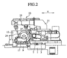
- FIGS. 1 and 2 show a roll grinder having a roll diameter measuring instrument in accordance with the invention.
- the roll grinder includes a carriage 3 reciprocating on a carriage mounting bed 1 in the direction of Z-axis identical to an axial direction of the roll, i.e. left and right directions in Fig. 1, a grinding wheel head 7 which is mounted on the carriage 3 so as to reciprocate in the direction of X-axis identical to left and right directions in Fig. 2 and which supports a grinding wheel 5 rotatably, a headstock 13 arranged on a work mounting bed 9 on the left side of Fig.
- Fig. 1 to have a main spindle 11, a footstock 17 arranged on the work mounting bed 9 so as to be displaceable in the direction of Z-axis and provided with a work center 15, and neckrests 19 arranged on the work mounting bed 9 between the headstock13 and the footstock 17.
- alphabet C denotes a center axis of the not-shown roll as an object to be ground, which is arranged between the headstock 13 and the work center 15.
- a roll diameter measuring instrument 23 is attached to the carriage 3 through an arm 21.
- the roll diameter measuring instrument 23 operates to measure a diameter of the roll by a coordinate difference between the gauge head 27 and the gauge head 29 in the direction of X-axis.
- the cross rail 25 extends in the direction of X-axis on the work mounting bed 9 horizontally.
- a master roll 33 Arranged on the back side of the footstock 17 is a master roll 33 which is fixed on the right end of the work mounting bed 9 of Fig. 1 through a bracket 31 in the form of yoke.
- the master roll 33 which includes a plurality of diametrical parts 33a, 33b, .... coaxially arranged to form a stepped conical configuration, is arranged in alignment with the center axis C of the roll above the work mounting bed 9. Both ranges of maximum and minimum diameters of the diametrical parts 33a, 33b, ... are determined corresponding to the measurable extent of the roll diameter measuring instrument 23 and each diametrical pitch among the parts 33a, 33b, ... is established in accordance with the required accuracy. When the measurable extent of the roll diameter is from 100 mm to 1000 mm, it would be preferable of 50 to 100 mm in diametrical pitch.
- the diameter measuring of the diametrical parts 33a, 33b,... of the master roll 33 is carried out by the roll diameter measuring instrument 23.
- FIG. 3 shows a structure of the roll diameter measuring apparatus of the invention.
- the apparatus includes standard diameter storing means 35 for storing "standard" diameters of the respective diametrical parts 33a, 33b,... measured under the standard temperature condition and roll diameter measurement correcting means 37 for calculating a difference between the diameter measurement of the master roll, which can be obtained by the roll diameter measuring instrument 23 measuring a diameter of the diametrical part having the standard diameter closest to the roll diameter, and the standard diameter stored in the storing means 35, as a correction value.
- the roll diameter measurement correcting means 37 further corrects the roll diameter measurement, which has been measured by the instrument 23, by the above correction value.
- the diameters of the respective diametrical parts 33a, 33b,... of the master roll 33 are measured under a condition at a predetermined "standard” temperature, so that the standard diameters of the parts 33a, 33b,... can be obtained and then stored in the standard diameter storing means 35.
- a diameter of one diametrical part, of which standard diameter is closest to the roll diameter is measured by means of the roll diameter measuring instrument 23. Then, a difference between the so-measured "master roll" diameter of the above diametrical part and the above standard diameter is calculated as a correction value and thereafter, the roll diameter measured by the roll diameter measuring instrument 23 is corrected by the correction value. Consequently, it is possible to obtain the precise absolute dimension of the roll diameter irrespective of largeness of the roll diameter.
- the measuring of the diametrical part of the master roll 33 and the calculation of the correction value have only to be carried out every measuring of the roll diameter or executed when the temperature varies over a predetermined value (e.g. b: constant) or when time has passed over another predetermined value (e.g. a: constant).
- Fig. 4 is a flow chart of master set routine by which the correction value is set against each of the diametrical parts 33a, 33b,... of the master roll 33.
- the respective diametrical parts 33a, 33b,... are measured by the roll diameter measuring instrument 23. Then, the resulting measurements, i.e. diameters of the diametrical parts are stored in a work memory etc. that the roll diameter measurement correcting means 37 possesses (step S10).
- step S20 it is executed to calculate the respective correction values for the respective diametrical parts 33a, 33b,... by subtracting the respective diameter measurements of the master roll from the standard diameters which have been previously stored for the respective diametrical parts 33a, 33b,... in the standard diameter storing means 35 and the routine goes to step 30 where the correction values are stored in the work memory.
- step S 40 it is executed to set the present time as the master set time and store it in the work memory.
- step S 50 it is executed to set the present temperature as the master set temperature and store it in the work memory.
- Fig. 5 shows a routine for measuring the roll diameter.
- this routine at step S100, it is judged whether time lag between the master set time and the present time, i.e. time passage since master set, is more than the predetermined value a (constant), while it is judged whether a difference between the master set temperature and the present temperature is more than the predetermined value b (constant) at step S 110.
- step S120 the routine goes to step S120 where the above mentioned master set routine is redone.
- step S130 the roll diameter of the now-shown roll on the work mounting bed 9 is measured by the roll diameter measuring instrument 23 since the master set at this time is believed to be effective.
- step S140 the correction value corresponding to the roll diameter, i.e. the correction value brought by the diametrical part of the master roll 33 closest to the roll diameter, is called from the memory.
- step S150 the roll diameter measurement is corrected by a calculation of adding the correction value into the roll diameter measurement and thereafter, the routine goes to step S160 where the measurement is registered.
Landscapes
- Engineering & Computer Science (AREA)
- Mechanical Engineering (AREA)
- Length Measuring Devices With Unspecified Measuring Means (AREA)
- Constituent Portions Of Griding Lathes, Driving, Sensing And Control (AREA)
Claims (8)
- Verfahren zum Messen eines Walzendurchmessers einer Walze, die an einem Walzenstreifer mit einer Walzendurchmesser-Messvorrichtung zum Messen des Walzendurchmessers montiert ist, derart, dass das Verfahren folgende Schritte enthält:Vorbereiten einer stufenförmigen, konischen Hauptwalze, betehend aus mehreren koaxial angeordneten, diametralen Teilen, derart, dass die jeweilige Durchmesser der diametralen Teile sich voneinander unterscheiden;Messen der Durchmesser der diametralen Teile unter einer Bedingung einer vorgegebenen Temperatur, damit Standarddurchmesserwerte der diametralen Teile erhalten werden;Montieren der Hauptwalze an dem Walzenschleifer zum Platzieren der Hauptwalze unter einer Temperaturbedingung, ähnlich zu derjenigen im Umfeld der an dem Walzenschleifer montierten Walze;Messen eines Durchmessers eines der diametralen Teile durch die Walzendurchmesser-Messvorrichtung, derart, dass der Standarddurchmesserwert des einen diametralen Teils am nächsten bei dem Walzendurchmesserwert der Walze liegt;Berechnen einer Differenz zwischen dem Durchmesserwert des einen diametralen Teils und des Standarddurchmesserwerts als Korrekturwert; undKorrigieren des Walzendurchmesserwerts der Walze, der durch die Walzendurchmesser-Messvorrichtung gemessen wird, durch den Korrekturwert.
- Verfahren nach Anspruch 1, dadurch gekennzeichnet, dass der Messschritt des einen diametralen Teils der Hauptwalze und der Berechnungsschritt für den Korrekturwert bei jedem Messen des Walzendurchmessers der Walze durchgeführt werden.
- Verfahren nach Anspruch 1, dadurch gekennzeichnet, dass der Messschritt für den einen diametralen Teil der Hauptwalze und den Berechnungsschritt für den Korrekturwert dann durchgeführt werden, wenn sich eine Umfeldtemperatur im Umfeld des Walzenschleifers über einen vorgegebenen Wert ändert.
- Verfahren nach Anspruch 1, dadurch gekennzeichnet, dass der Messschritt für den einen diametralen Teil der Hauptwalze und der Berechnungsschritt für den Korrekturwert dann durchgeführt werden, wenn eine Zeit über einen vorgegebenen Wert verstrichen ist.
- Gerät zum Messen eines Walzendurchmessers einer Walze, die an einem Walzenschleifer montiert ist, mit einem Vorschub bzw. Schlitten für eine Hin- und Herbewegung entlang der Axialrichtung der Walze, einem an dem Schlitten montierten Schleifscheibenkopf und einem Werkstückeinspannbett bzw. -gestell zum Montieren der Walze hieran, derart, dass das Gerät enthält:eine Walzendurchmesser-Messvorrichtung zum Messen des Walzendurchmessers der Walze, derart, dass die Walzendurchmesser-Messvorrichtung an dem Schlitten montiert ist und bewegliche Messzellen aufweist;eine stufenförmige, konische Hauptwalze, die in Ausrichtung zu einer Mittenachse der Walze angeordnet ist, die an dem Werkstückeinspanngestell montiert ist, derart, dass die Hauptwalze mehrere diametrale Teile aufweist, deren Durchmesser sich voneinander unterscheiden;eine Standarddurchmesserwert-Speichervorrichtung zum Speichern eines Standarddurchmesserwerts der diametralen Teile, derart, dass der Standarddurchmesserwert durch Messen jeweiliger Durchmesser der diametralen Teile der Hauptwalze unter einer Bedingung einer vorgegebenen Temperatur erhalten wird; undeine Walzendurchmesser-Messkorrekturvorrichtung zum Berechnen einer Differenz zwischen einem Durchmesserwert eines der diametralen Teile, von dem der Standarddurchmesserwert am nächsten bei der durch die Walzendurchmesser-Messvorrichtung gemessenen Walzendurchmesserwert liegt, sowie dem in der Standarddurchmesser-Speichervorrichtung gespeicherten Standarddurchmesserwert als Korrekturwert und zum Korrigieren des durch die Walzendurchmesser-Messvorrichtung gemessenen Walzendurchmesserwerts gemäss dem Korrekturwert.
- Gerät nach Anspruch 5, dadurch gekennzeichnet, dass die Walzendurchmesser-Messvorrichtung einen Betrieb zum Messen des einen diametralen Teils der Hauptwalze bei jedem Messen des Walzendurchmessers der Walze ausführt und auch die Walzendurchmesser-Messkorrekturvorrichtung einen Betrieb zum Berechnen des Korrekturwerts bei jedem Messen des Walzendurchmessers der Walze ausführt.
- Gerät nach Anspruch 5, dadurch gekennzeichnet, dass die Walzendurchmesser-Messvorrichtung einen Betrieb zum Messen des einen diametralen Teils der Hauptwalze ausführt und die Walzendurchmesser-Messkorrekturvorrichtung einen Betrieb zum Berechnen des Korrekturwerts dann ausführt, wenn sich eine Umfeldtemperatur um den Walzenschleifer über einen vorgegebenen Wert ändert.
- Gerät nach Anspruch 5, dadurch gekennzeichnet, dass die Walzendurchmesser-Messvorrichtung einen Betrieb zum Messen des einen diametralen Teils der Hauptwalze ausführt und die Walzendurchmesser-Messkorrekturvorrichtung einen Betrieb zum Berechnen des Korrekturwerts dann ausführt, wenn eine Zeit über einem vorgegebenen Wert verstrichen ist.
Applications Claiming Priority (3)
| Application Number | Priority Date | Filing Date | Title |
|---|---|---|---|
| JP13860996 | 1996-05-31 | ||
| JP8138609A JPH09323257A (ja) | 1996-05-31 | 1996-05-31 | ロール研削盤におけるロール径計測方法およびロール径計測装置 |
| JP138609/96 | 1996-05-31 |
Publications (2)
| Publication Number | Publication Date |
|---|---|
| EP0810067A1 EP0810067A1 (de) | 1997-12-03 |
| EP0810067B1 true EP0810067B1 (de) | 2000-10-18 |
Family
ID=15226090
Family Applications (1)
| Application Number | Title | Priority Date | Filing Date |
|---|---|---|---|
| EP96113843A Expired - Lifetime EP0810067B1 (de) | 1996-05-31 | 1996-08-29 | Verfahren und Gerät zum Messen des Durchmessers einer Walze in einer Walzenschleifmaschine |
Country Status (4)
| Country | Link |
|---|---|
| US (1) | US5771599A (de) |
| EP (1) | EP0810067B1 (de) |
| JP (1) | JPH09323257A (de) |
| DE (1) | DE69610694T2 (de) |
Cited By (1)
| Publication number | Priority date | Publication date | Assignee | Title |
|---|---|---|---|---|
| CN105773421A (zh) * | 2014-12-26 | 2016-07-20 | 鞍钢股份有限公司 | 一种轧辊磨床球形可调节测量探头 |
Families Citing this family (11)
| Publication number | Priority date | Publication date | Assignee | Title |
|---|---|---|---|---|
| IT1279641B1 (it) | 1995-10-03 | 1997-12-16 | Marposs Spa | Apparecchio per il controllo del diametro di perni di biella in moto orbitale |
| IT1321212B1 (it) * | 2000-03-06 | 2003-12-31 | Marposs Spa | Apparecchiatura per il controllo del diametro di perni . |
| KR20020045643A (ko) * | 2000-12-09 | 2002-06-20 | 이구택 | 압연기용 롤의 직경 및 원호측정 장치 |
| JP5251429B2 (ja) * | 2008-10-30 | 2013-07-31 | 株式会社ジェイテクト | 研削盤 |
| DE102009032353A1 (de) | 2009-07-08 | 2011-09-08 | Hommel-Etamic Gmbh | Verfahren zur Ermittlung der Form eines Werkstücks |
| DE102009042252B4 (de) | 2009-09-22 | 2014-03-06 | Jenoptik Industrial Metrology Germany Gmbh | Meßvorrichtung |
| DE102010013069B4 (de) | 2010-03-26 | 2012-12-06 | Hommel-Etamic Gmbh | Meßvorrichtung |
| DE102010035147B4 (de) | 2010-08-23 | 2016-07-28 | Jenoptik Industrial Metrology Germany Gmbh | Meßvorrichtung |
| DE102012018580B4 (de) | 2012-09-20 | 2015-06-11 | Jenoptik Industrial Metrology Germany Gmbh | Messvorrichtung und Messverfahren zur Inprozess-Messung an Prüflingen während eines Bearbeitungsvorganges an einer Bearbeitungsmaschine, insbesondere einer Schleifmaschine |
| CN109773614B (zh) * | 2018-12-03 | 2021-04-20 | 宁波公牛电器有限公司 | 倒角机及倒角加工方法 |
| CN114523417A (zh) * | 2022-03-15 | 2022-05-24 | 常州曲线数控科技有限公司 | 一种轧辊磨床砂轮直径检测方法 |
Family Cites Families (11)
| Publication number | Priority date | Publication date | Assignee | Title |
|---|---|---|---|---|
| DE35627C (de) * | BR. meinert in Berlin SW., Bernburgerstr. 18 | Apparate zur mechanischen Schaustellung grofser Waarenmengen | ||
| US3332153A (en) * | 1964-08-31 | 1967-07-25 | Bausch & Lomb | Temperature compensating system |
| JPS55130512A (en) * | 1979-03-30 | 1980-10-09 | Canon Inc | Semiconductor laser optical system |
| DE3009180C2 (de) * | 1980-03-11 | 1982-04-15 | Estel Hoesch Werke Ag, 4600 Dortmund | Steuereinrichtung zum Zustellen der längsverschiebbaren Schleifscheibe einer Walzenschleifmaschine |
| DE3013378C2 (de) * | 1980-04-05 | 1984-12-20 | FAG Kugelfischer Georg Schäfer KGaA, 8720 Schweinfurt | Einrichtung zur adaptiven Regelung von Bearbeitungsprozessen an Schleifmaschinen, insbesondere an Rundschleifmaschinen |
| JPS5822659A (ja) * | 1981-07-31 | 1983-02-10 | Mizuguchi Seisakusho:Kk | 円筒研削盤の定寸方法 |
| US5042161A (en) * | 1985-10-07 | 1991-08-27 | Joseph Hodge | Intravascular sizing method and apparatus |
| IT1191688B (it) * | 1986-03-20 | 1988-03-23 | Giustina International Spa | Macchina rettificatrice per cilindri con organi di rilievo e controllo dimensionale e superficiale |
| FR2621267A1 (fr) * | 1987-10-01 | 1989-04-07 | Meseltron Sa | Procede et equipement de mesure pour la commande automatique de l'avance et du recul de la meule d'une rectifieuse plane |
| US5052121A (en) * | 1988-07-01 | 1991-10-01 | Albion Devices, Inc. | Temperature-compensated quantitative dimensional measurement device with rapid temperature sensing and compensation |
| DE3828181A1 (de) * | 1988-08-19 | 1990-03-08 | Voith Gmbh J M | Messvorrichtung, insbesondere zur messung der durchmesser von walzen bei walzenschleifmaschinen |
-
1996
- 1996-05-31 JP JP8138609A patent/JPH09323257A/ja active Pending
- 1996-08-29 US US08/704,998 patent/US5771599A/en not_active Expired - Lifetime
- 1996-08-29 EP EP96113843A patent/EP0810067B1/de not_active Expired - Lifetime
- 1996-08-29 DE DE69610694T patent/DE69610694T2/de not_active Expired - Lifetime
Cited By (1)
| Publication number | Priority date | Publication date | Assignee | Title |
|---|---|---|---|---|
| CN105773421A (zh) * | 2014-12-26 | 2016-07-20 | 鞍钢股份有限公司 | 一种轧辊磨床球形可调节测量探头 |
Also Published As
| Publication number | Publication date |
|---|---|
| JPH09323257A (ja) | 1997-12-16 |
| US5771599A (en) | 1998-06-30 |
| DE69610694D1 (de) | 2000-11-23 |
| DE69610694T2 (de) | 2001-05-03 |
| EP0810067A1 (de) | 1997-12-03 |
Similar Documents
| Publication | Publication Date | Title |
|---|---|---|
| EP0810067B1 (de) | Verfahren und Gerät zum Messen des Durchmessers einer Walze in einer Walzenschleifmaschine | |
| US5276974A (en) | Unit for continuously measuring shape defects of a part, and measuring process used in this unit. | |
| EP0787280B1 (de) | Rundheitsmessen | |
| JP6419575B2 (ja) | 工作機械およびワークピース測定方法 | |
| US7617965B2 (en) | Method for measuring loads on a friction stir welding tool | |
| US20160124420A1 (en) | Thermal displacement correcting apparatus and method for a machine tool | |
| US20010029778A1 (en) | Surface texture measuring instrument, surface texture measuring method and stylus radius measuring instrument | |
| US7206716B2 (en) | Wheel alignment with surface-oriented runout determination | |
| US11243062B2 (en) | Position measurement method and position measurement system of object in machine tool, and computer-readable recording medium | |
| CN112008491A (zh) | 一种基于测头的ca型五轴数控机床rtcp精度标定方法 | |
| CN112355712B (zh) | 一种触发式在机测量的精度校准方法及系统 | |
| US6427346B1 (en) | Method and apparatus for calibration of no-compensation and universal wheel adapters utilized in vehicle wheel alignment procedures | |
| US5773731A (en) | Method and apparatus for detecting residual grinding amount | |
| JP3199627B2 (ja) | 両頭研削盤における自動定寸装置及び方法 | |
| EP3334562B1 (de) | Schleiffehlerkompensierung | |
| JPH0577159A (ja) | 研削盤の被削材たわみ量演算方法 | |
| JP2602965B2 (ja) | 自動円筒研削装置 | |
| US5653040A (en) | One touch face gage for vehicle wheels | |
| US20250114907A1 (en) | Method for calibrating a dressing spindle of a machine tool | |
| JPS6274507A (ja) | 2刃物台を有する4軸制御nc旋盤の刃物台原点の修正方法 | |
| JP2713584B2 (ja) | 工作機械の寸法制御方法 | |
| JP3275583B2 (ja) | ホーニング加工量補正装置および補正方法 | |
| CN118719865B (zh) | 冲压件尺寸控制方法 | |
| JP2008083015A (ja) | 車両流れ量の管理方法,推定方法およびシステム | |
| JPH10239012A (ja) | 輪郭形状測定方法及び輪郭形状測定機 |
Legal Events
| Date | Code | Title | Description |
|---|---|---|---|
| PUAI | Public reference made under article 153(3) epc to a published international application that has entered the european phase |
Free format text: ORIGINAL CODE: 0009012 |
|
| 17P | Request for examination filed |
Effective date: 19960829 |
|
| AK | Designated contracting states |
Kind code of ref document: A1 Designated state(s): DE IT |
|
| GRAG | Despatch of communication of intention to grant |
Free format text: ORIGINAL CODE: EPIDOS AGRA |
|
| 17Q | First examination report despatched |
Effective date: 19990924 |
|
| GRAG | Despatch of communication of intention to grant |
Free format text: ORIGINAL CODE: EPIDOS AGRA |
|
| GRAH | Despatch of communication of intention to grant a patent |
Free format text: ORIGINAL CODE: EPIDOS IGRA |
|
| RAP1 | Party data changed (applicant data changed or rights of an application transferred) |
Owner name: TOSHIBA KIKAI KABUSHIKI KAISHA |
|
| GRAH | Despatch of communication of intention to grant a patent |
Free format text: ORIGINAL CODE: EPIDOS IGRA |
|
| GRAA | (expected) grant |
Free format text: ORIGINAL CODE: 0009210 |
|
| AK | Designated contracting states |
Kind code of ref document: B1 Designated state(s): DE IT |
|
| REF | Corresponds to: |
Ref document number: 69610694 Country of ref document: DE Date of ref document: 20001123 |
|
| ITF | It: translation for a ep patent filed | ||
| EN | Fr: translation not filed | ||
| PLBE | No opposition filed within time limit |
Free format text: ORIGINAL CODE: 0009261 |
|
| STAA | Information on the status of an ep patent application or granted ep patent |
Free format text: STATUS: NO OPPOSITION FILED WITHIN TIME LIMIT |
|
| 26N | No opposition filed | ||
| PG25 | Lapsed in a contracting state [announced via postgrant information from national office to epo] |
Ref country code: IT Free format text: LAPSE BECAUSE OF NON-PAYMENT OF DUE FEES Effective date: 20100829 |
|
| PGRI | Patent reinstated in contracting state [announced from national office to epo] |
Ref country code: IT Effective date: 20110616 |
|
| PGFP | Annual fee paid to national office [announced via postgrant information from national office to epo] |
Ref country code: DE Payment date: 20130821 Year of fee payment: 18 |
|
| PGFP | Annual fee paid to national office [announced via postgrant information from national office to epo] |
Ref country code: IT Payment date: 20130819 Year of fee payment: 18 |
|
| REG | Reference to a national code |
Ref country code: DE Ref legal event code: R119 Ref document number: 69610694 Country of ref document: DE |
|
| PG25 | Lapsed in a contracting state [announced via postgrant information from national office to epo] |
Ref country code: IT Free format text: LAPSE BECAUSE OF NON-PAYMENT OF DUE FEES Effective date: 20140829 |
|
| REG | Reference to a national code |
Ref country code: DE Ref legal event code: R119 Ref document number: 69610694 Country of ref document: DE Effective date: 20150303 |
|
| PG25 | Lapsed in a contracting state [announced via postgrant information from national office to epo] |
Ref country code: DE Free format text: LAPSE BECAUSE OF NON-PAYMENT OF DUE FEES Effective date: 20150303 |