EP0811409A1 - Aspirateur jouet - Google Patents
Aspirateur jouet Download PDFInfo
- Publication number
- EP0811409A1 EP0811409A1 EP97303686A EP97303686A EP0811409A1 EP 0811409 A1 EP0811409 A1 EP 0811409A1 EP 97303686 A EP97303686 A EP 97303686A EP 97303686 A EP97303686 A EP 97303686A EP 0811409 A1 EP0811409 A1 EP 0811409A1
- Authority
- EP
- European Patent Office
- Prior art keywords
- vacuum cleaner
- housing
- toy vacuum
- chamber
- toy
- Prior art date
- Legal status (The legal status is an assumption and is not a legal conclusion. Google has not performed a legal analysis and makes no representation as to the accuracy of the status listed.)
- Withdrawn
Links
- 239000004744 fabric Substances 0.000 claims abstract description 26
- 230000002441 reversible effect Effects 0.000 claims description 4
- 239000012780 transparent material Substances 0.000 claims 1
- 229920003023 plastic Polymers 0.000 description 11
- 239000004033 plastic Substances 0.000 description 10
- 239000000463 material Substances 0.000 description 5
- 239000004677 Nylon Substances 0.000 description 4
- 229920001778 nylon Polymers 0.000 description 4
- 229920006328 Styrofoam Polymers 0.000 description 1
- 230000004913 activation Effects 0.000 description 1
- 238000004140 cleaning Methods 0.000 description 1
- 239000003086 colorant Substances 0.000 description 1
- 238000010586 diagram Methods 0.000 description 1
- 238000009429 electrical wiring Methods 0.000 description 1
- 239000003562 lightweight material Substances 0.000 description 1
- 239000008261 styrofoam Substances 0.000 description 1
- 210000003813 thumb Anatomy 0.000 description 1
- 125000000391 vinyl group Chemical group [H]C([*])=C([H])[H] 0.000 description 1
- 229920002554 vinyl polymer Polymers 0.000 description 1
Images


Classifications
-
- A—HUMAN NECESSITIES
- A63—SPORTS; GAMES; AMUSEMENTS
- A63H—TOYS, e.g. TOPS, DOLLS, HOOPS OR BUILDING BLOCKS
- A63H33/00—Other toys
- A63H33/30—Imitations of miscellaneous apparatus not otherwise provided for, e.g. telephones, weighing-machines, cash-registers
- A63H33/305—Vacuum-cleaners
Definitions
- the invention relates to a toy vacuum cleaner comprising a housing defining an interior cavity; a battery-operated motor positioned in the housing; and a fan positioned in the housing and configured to be driven by the motor.
- the invention features a toy vacuum cleaner capable of picking up lightweight objects such as nylon fabric pieces.
- the toy vacuum cleaner includes a housing defining an interior cavity, a battery-operated motor positioned in the housing, a fan positioned in the housing, and wheels connected to the housing.
- vacuum cleaners intended for use as cleaning tools typically include impellers instead of fans.
- the fan is configured to be driven by the motor through, for example, a drive shaft connected between the fan and the motor.
- Embodiments of the invention may include one or more of the following features.
- the housing may be sized and shaped to resemble a miniature "shop vac".
- a chamber may be positioned on top of the housing.
- the chamber may include a first port between the chamber and the interior cavity of the housing and a second port between the chamber and an external environment.
- the fan may be positioned at the first port, and the vacuum may further include a screen positioned between the interior cavity and the chamber. The screen helps to prevent materials from being drawn into the fan.
- the housing may include an opening through which materials may be discharged.
- the chamber may be defined by a cover positioned on top of the housing.
- the cover may be made from transparent plastic and may be removably and/or rotatably mounted on top of the housing.
- a nozzle may be positioned on top of the housing. If so, the cover may be rotatable from a first position in which the second port is aligned with the nozzle and a second position in which the second port is spaced from the nozzle.
- the cover may include stops configured to prevent the cover from rotating beyond an arc defined by the first and second positions.
- a translucent hose may be attached to the nozzle.
- the toy vacuum cleaner may also include a battery positioned in the interior cavity and connected to the motor, and a switch connected between the battery and the motor.
- the motor may be reversible so that the toy vacuum cleaner may also function as a blower.
- the switch may be configured to be selectably positioned in a first position in which the motor is deactivated, a second position in which the motor rotates in a first direction, and a third position in which the motor rotates in a second direction.
- a collection of colorful fabric pieces or other objects may be provided with the toy vacuum cleaner.
- the toy vacuum cleaner is configured to produce suction sufficient to pick up the fabric pieces.
- the colorful fabric pieces may be viewed as they travel through the translucent hose and move around in the chamber defined by the transparent cover. The movement of the colorful fabric pieces entertains the small children for whom the toy vacuum cleaner is designed, which substantially increases the play value of the toy.
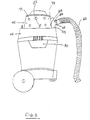
- a toy vacuum cleaner 10 includes a housing unit 15 having a cover 20 and a bottom portion 25.
- Cover 20 and bottom portion 25 may be made from plastic.
- Two releasable latches 30 are formed as part of the cover 20 and bottom portion 25 of the housing unit 15, and are arranged to hold those components in place.
- the cover 20 also includes a side aperture 95 that permits air to flow out of the housing unit 15.
- the toy vacuum cleaner 10 is supported by three wheels. Two large wheels 35 are attached to the front sides of the bottom portion 25 and one small wheel 40 is attached to the rear of the bottom portion.
- the toy vacuum cleaner 10 also includes a clear plastic housing 45 attached to the top of the cover 20. The housing 45 defines a chamber 48.
- the cover 20 includes an extension 55 to which is attached a nozzle 50.
- the extension 55 includes an opening 57 that communicates with the nozzle 50 and with an opening in the housing 45.
- the nozzle 50 extends horizontally from the opening 57.
- a removable, translucent hose 60 is attached to the nozzle 50 (FIGS. 1 and 3).
- the hose 60 is attached by sliding the hose 60 onto the nozzle 50.
- the hose 60 is held on the nozzle 50 by an interference fit.
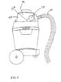
- the hose 60 is configured to be grasped by the hand of a child using the toy vacuum cleaner 10 to pick up material such as the nylon fabric pieces 70 shown in FIG. 1. As shown in FIG. 3, the nylon pieces 70 are received within the clear plastic housing 45 after they have been vacuumed up through the hose 60. Fabric pieces 70 can be observed as they spin around in the clear plastic housing 45.
- the housing 45 includes a side opening 75 and two rotation stops 130, 132.
- FIG. 3 shows the housing 45 positioned with the side opening 75 aligned with the opening 57 in the extension 55 of the cover 20.
- a negative pressure created in the chamber 48 creates a negative pressure in the hose 60 that permits the hose to pick up the fabric pieces 70.
- the rotation stop 130 rests against the extension 55 of the cover 20 and the rotation stop 132 is spaced from the extension 55.
- FIG. 4 shows the housing 45 positioned with the side opening 75 not being aligned with the opening 57 in the extension 55 of the cover 20. In this alignment, negative pressure in the chamber 48 draws air through the opening 57 into the chamber 48, and negative pressure is not created in the hose 60.
- the rotation stop 132 rests against the extension 55 of the cover 20 and the rotation stop 130 is spaced away from the extension 55. The arc of rotation of the housing 45 is limited by the positioning of the stops 130, 132.
- a three-bladed fan 85 is mounted in the housing unit 15 beneath the cover 20.
- a screen 90 is formed in the cover 20 and serves to prevent objects in the chamber 48 from reaching the fan 85.
- the fan 85 produces a negative pressure in the chamber 48 that results in an air flow that enters the chamber 48 through the opening 75, passes through screen 90 and emerges from housing unit 15 through the side aperture 95.
- Nylon fabric pieces 70 that are vacuumed into the chamber 48 are intercepted by the screen 90 and do not reach the fan 85. Instead, the fabric pieces move around within the chamber 48.
- the fabric pieces are made from fabric having different colors so that movement of the fabric pieces creates changing, colorful patterns that entertain a child playing with the toy vacuum cleaner 10 and increase the play value of the toy.
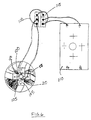
- the housing unit 15 contains the fan 85 and a reversible motor 80. As shown in FIG. 6, a drive shaft 105 couples the motor 80 to the fan 85. Rotation of the shaft 105 and the fan 85 by the motor 80 creates a negative pressure and accompanying suction that draws air and the fabric pieces 70 into the chamber 48 in the clear plastic housing 45. The air exits the housing unit 15 through the side aperture 95. The fabric pieces 70 are blocked by the screen 90 and trapped in the chamber 48.
- the motor 80 may be reversed to create a positive pressure in the chamber 48 and a negative pressure in the housing unit 15.
- the negative pressure in the housing unit 15 causes air to flow into the housing unit 15 through the side aperture 95.
- the air then flows from the housing unit 15 into the chamber 48.
- the positive pressure in the chamber 48 causes air to flow out of the chamber 48 through the opening 75 (and through the hose 60 if the hose is aligned with the opening 75).
- the flow of air out of the chamber 48 causes the fabric pieces 70 to exit the chamber 48.
- the motor 80 is powered by a battery 110.
- a switch 115 is positioned on the top of the cover 20 for convenient engagement by means of the thumb of a child utilizing the toy vacuum cleaner 10. The switch 115 operates to selectively supply electric power from the battery 110 to the motor 80 for activation of the motor 80.
- Electrical wiring 120 interconnects the battery 110, the switch 115, and the motor 80.
- switch 115 When switch 115 is placed in an ON position, motor 80 is activated by the battery 110 and causes the fan 85 to operate. Operation of fan 85 causes an air flow (indicated by the arrows 67 in FIG. 1) inwardly through hose 60 and outwardly through side aperture 95. The screen 90 prevents any of the fabric pieces 70 or other materials from passing into the fan 85 and motor 80.
- the switch 115 When the switch 115 is in an OFF position, the motor 80 is deactivated.
- the switch 115 may be placed in a third position that causes the motor 80 and the fan 85 to rotate in a reverse direction. This causes the fabric pieces 70 to blow around the interior of the clear plastic housing 45. The fabric pieces 70 may also fly out of the housing 45 when the blower is turned on from either the opening 65 in the hose 60 or through the side opening 75 of the housing 45.
- the latter is opened by simply rotating the plastic housing 45. Because the plastic housing 45 consists of transparent, impact-resistance plastic, the contents of the chamber 48 can be viewed without opening the housing 45.
- the chamber defined by the transparent housing may include an enclosed portion in which fabric pieces are permanently positioned.
- the enclosed portion would include holes positioned to permit air flow from the fan to cause the fabric pieces to move around within the enclosed portion.
- the fabric pieces could be replaced with pieces of vinyl or other sheet materials, pieces of styrofoam, or any other lightweight material.
Landscapes
- Toys (AREA)
Applications Claiming Priority (2)
| Application Number | Priority Date | Filing Date | Title |
|---|---|---|---|
| US65507096A | 1996-06-03 | 1996-06-03 | |
| US655070 | 1996-06-03 |
Publications (1)
| Publication Number | Publication Date |
|---|---|
| EP0811409A1 true EP0811409A1 (fr) | 1997-12-10 |
Family
ID=24627380
Family Applications (1)
| Application Number | Title | Priority Date | Filing Date |
|---|---|---|---|
| EP97303686A Withdrawn EP0811409A1 (fr) | 1996-06-03 | 1997-06-02 | Aspirateur jouet |
Country Status (3)
| Country | Link |
|---|---|
| EP (1) | EP0811409A1 (fr) |
| AU (1) | AU2463897A (fr) |
| CA (1) | CA2206798A1 (fr) |
Cited By (1)
| Publication number | Priority date | Publication date | Assignee | Title |
|---|---|---|---|---|
| GB2331712A (en) * | 1998-01-09 | 1999-06-02 | Cassidy Brothers Plc | Toy Vacuum Cleaner |
Families Citing this family (1)
| Publication number | Priority date | Publication date | Assignee | Title |
|---|---|---|---|---|
| AU704256B3 (en) * | 1997-08-28 | 1999-04-15 | Dyson Appliances Limited | Toy vacuum cleaner |
Citations (3)
| Publication number | Priority date | Publication date | Assignee | Title |
|---|---|---|---|---|
| DE1478612A1 (de) * | 1962-02-23 | 1969-07-17 | Neuhierl Dr Hermann | Spielzeug in Gestalt eines Staubsaugers |
| DE1603626A1 (de) * | 1966-05-03 | 1971-07-15 | Trossinger Metallstimmenfab H | Mechanisches Spielzeug |
| FR2222986A1 (en) * | 1973-03-29 | 1974-10-25 | Baquet Daniel | Battery powered toy vacuum cleaner - has central base plate which supports motor etc. and two part casing |
-
1997
- 1997-06-02 AU AU24638/97A patent/AU2463897A/en not_active Abandoned
- 1997-06-02 EP EP97303686A patent/EP0811409A1/fr not_active Withdrawn
- 1997-06-03 CA CA 2206798 patent/CA2206798A1/fr not_active Abandoned
Patent Citations (3)
| Publication number | Priority date | Publication date | Assignee | Title |
|---|---|---|---|---|
| DE1478612A1 (de) * | 1962-02-23 | 1969-07-17 | Neuhierl Dr Hermann | Spielzeug in Gestalt eines Staubsaugers |
| DE1603626A1 (de) * | 1966-05-03 | 1971-07-15 | Trossinger Metallstimmenfab H | Mechanisches Spielzeug |
| FR2222986A1 (en) * | 1973-03-29 | 1974-10-25 | Baquet Daniel | Battery powered toy vacuum cleaner - has central base plate which supports motor etc. and two part casing |
Cited By (2)
| Publication number | Priority date | Publication date | Assignee | Title |
|---|---|---|---|---|
| GB2331712A (en) * | 1998-01-09 | 1999-06-02 | Cassidy Brothers Plc | Toy Vacuum Cleaner |
| GB2331712B (en) * | 1998-01-09 | 1999-10-13 | Cassidy Brothers Plc | Toy vacuum cleaner |
Also Published As
| Publication number | Publication date |
|---|---|
| CA2206798A1 (fr) | 1997-12-03 |
| AU2463897A (en) | 1997-12-11 |
Similar Documents
| Publication | Publication Date | Title |
|---|---|---|
| US4775348A (en) | Bubble machine | |
| CA1199456A (fr) | Outil d'aspirateur pour le nettoyage des surfaces horizontales et verticales | |
| CA2465859A1 (fr) | Nettoyeuse aspirante | |
| JPH03267598A (ja) | 送風装置 | |
| JPH09192056A (ja) | 眞空掃除機 | |
| US3715775A (en) | Vacuum cleaner | |
| US5659920A (en) | Blower vacuum device of improved design | |
| JP2003204904A5 (fr) | ||
| US6079079A (en) | Vacuum cleaner including ventilation fan for forming air current flowing along the axial direction of rotary brush to suction member | |
| WO2004010838A2 (fr) | Dispositif de soufflage depoussierant a main portatif fonctionnant sur pile | |
| EP0811409A1 (fr) | Aspirateur jouet | |
| JP2002320935A (ja) | ほこり払い器 | |
| JP2954431B2 (ja) | 電気掃除機の吸口体及びこの吸口体を用いた電気掃除機 | |
| US20030000042A1 (en) | Eraser having selectively openable and closable aperatures | |
| CN201200375Y (zh) | 可分离吹机吸尘器 | |
| EP1697198A1 (fr) | Poussette comprenant un jouet | |
| KR100278756B1 (ko) | 전기 청소기 | |
| CA2625736A1 (fr) | Dispositif aspirateur/souffleur mobile | |
| JP3300607B2 (ja) | 電気掃除機 | |
| CN221267123U (zh) | 一种可装拆使用的泡泡机组件 | |
| JP3300574B2 (ja) | 電気掃除機の吸口体及びこれを備えた電気掃除機 | |
| KR0140763B1 (ko) | 진공청소기의 물걸레 이송장치 | |
| JP2005348914A (ja) | 電気掃除機 | |
| JP3300573B2 (ja) | 電気掃除機の吸口体及びこれを備えた電気掃除機 | |
| JPH10165336A (ja) | 電気掃除機の吸込口体 |
Legal Events
| Date | Code | Title | Description |
|---|---|---|---|
| PUAI | Public reference made under article 153(3) epc to a published international application that has entered the european phase |
Free format text: ORIGINAL CODE: 0009012 |
|
| AK | Designated contracting states |
Kind code of ref document: A1 Designated state(s): AT BE CH DE DK ES FI FR GB IT LI LU NL |
|
| RIN1 | Information on inventor provided before grant (corrected) |
Inventor name: RUGGIERO, JAMES A. Inventor name: JENKINS, BARBARA P. |
|
| AKX | Designation fees paid |
Inventor name: RUGGIERO, JAMES A. |
|
| RBV | Designated contracting states (corrected) |
Inventor name: RUGGIERO, JAMES A. |
|
| RBV | Designated contracting states (corrected) |
Inventor name: RUGGIERO, JAMES A. |
|
| STAA | Information on the status of an ep patent application or granted ep patent |
Free format text: STATUS: THE APPLICATION IS DEEMED TO BE WITHDRAWN |
|
| 18D | Application deemed to be withdrawn |
Effective date: 19980611 |