EP0813288A1 - Segmentierte Ankerwicklung für Gleichstrommotor - Google Patents
Segmentierte Ankerwicklung für Gleichstrommotor Download PDFInfo
- Publication number
- EP0813288A1 EP0813288A1 EP96304334A EP96304334A EP0813288A1 EP 0813288 A1 EP0813288 A1 EP 0813288A1 EP 96304334 A EP96304334 A EP 96304334A EP 96304334 A EP96304334 A EP 96304334A EP 0813288 A1 EP0813288 A1 EP 0813288A1
- Authority
- EP
- European Patent Office
- Prior art keywords
- commutating
- electric machine
- primary
- brushes
- strips
- Prior art date
- Legal status (The legal status is an assumption and is not a legal conclusion. Google has not performed a legal analysis and makes no representation as to the accuracy of the status listed.)
- Withdrawn
Links
- 238000004804 winding Methods 0.000 title description 15
- 150000001875 compounds Chemical class 0.000 claims 1
- 230000004907 flux Effects 0.000 description 10
- 230000005284 excitation Effects 0.000 description 7
- 230000008878 coupling Effects 0.000 description 3
- 238000010168 coupling process Methods 0.000 description 3
- 238000005859 coupling reaction Methods 0.000 description 3
- XEEYBQQBJWHFJM-UHFFFAOYSA-N Iron Chemical group [Fe] XEEYBQQBJWHFJM-UHFFFAOYSA-N 0.000 description 2
- 239000004020 conductor Substances 0.000 description 2
- 230000006698 induction Effects 0.000 description 2
- 230000001939 inductive effect Effects 0.000 description 2
- 238000006243 chemical reaction Methods 0.000 description 1
- 101150084411 crn1 gene Proteins 0.000 description 1
- 230000004048 modification Effects 0.000 description 1
- 238000012986 modification Methods 0.000 description 1
- 230000010349 pulsation Effects 0.000 description 1
Images


Classifications
-
- H—ELECTRICITY
- H02—GENERATION; CONVERSION OR DISTRIBUTION OF ELECTRIC POWER
- H02K—DYNAMO-ELECTRIC MACHINES
- H02K23/00—DC commutator motors or generators having mechanical commutator; Universal AC/DC commutator motors
- H02K23/26—DC commutator motors or generators having mechanical commutator; Universal AC/DC commutator motors characterised by the armature windings
- H02K23/28—DC commutator motors or generators having mechanical commutator; Universal AC/DC commutator motors characterised by the armature windings having open windings, i.e. not closed within the armatures
-
- H—ELECTRICITY
- H02—GENERATION; CONVERSION OR DISTRIBUTION OF ELECTRIC POWER
- H02K—DYNAMO-ELECTRIC MACHINES
- H02K23/00—DC commutator motors or generators having mechanical commutator; Universal AC/DC commutator motors
- H02K23/26—DC commutator motors or generators having mechanical commutator; Universal AC/DC commutator motors characterised by the armature windings
- H02K23/36—DC commutator motors or generators having mechanical commutator; Universal AC/DC commutator motors characterised by the armature windings having two or more windings; having two or more commutators; having two or more stators
-
- H—ELECTRICITY
- H02—GENERATION; CONVERSION OR DISTRIBUTION OF ELECTRIC POWER
- H02K—DYNAMO-ELECTRIC MACHINES
- H02K41/00—Propulsion systems in which a rigid body is moved along a path due to dynamo-electric interaction between the body and a magnetic field travelling along the path
- H02K41/02—Linear motors; Sectional motors
- H02K41/035—DC motors; Unipolar motors
Definitions
- the present invention relates to DC machines, and more particularly, to a DC machine having a primary (in a rotary embodiment this might be the stator) of limited or infinite length (or circumference), and even more particularly, to a DC machine wherein a primary (or stator) is furnished with conductive segments forming non-closed loop excitation coils, each coil having two spaced-apart ends.
- the armatures of traditional DC machines are generally furnished with either lap windings or wave windings. No matter which one of these two types of windings are furnished, the ending lead will return to the starting lead to form a closed loop. This constraint renders it impractical to use these traditional windings in certain situations. For example, lap windings or wave windings are impractical in linear motors because the coils begin and end at remote positions along an elongate primary core. Hence, it would be awkward to bring the ending lead back to the starting lead in order to form a closed loop.
- a DC machine comprises a primary having a plurality of coils, each said coil having a first end portion, a coiled medial portion and a second end portion spaced from the first end portion, said coils being wound with said first end portions aligned along a first edge of said primary and with said second portion aligned along a second edge of said primary opposite said first edge, a secondary having a linearly disposed series of magnetic poles of alternate polarity, said magnetic poles being supported in facing relationship to said primary, commutating means including a plurality of first and second conductive commutating strips (or brushes), said first and second commutating strips (or brushes) each having a length substantially equal to or slightly shorter than the length of one of said magnetic poles, said first commutating strips (or brushes) each being supported along one side of one of said magnetic poles and extending parallel to said first edge of said primary substantially coextensively with said one side of said one magnetic pole so as to contact simultaneously said first end portions of the said coils
- the coils are typically discrete and arranged side-by-side in a series of limited or infinite length.
- the secondary (or rotor) commutates successive groups of the primary coils together as it moves relative thereto.
- the primary may be easily extended to any length, and is thereby especially suited for use in linear DC machines.
- the present invention is a DC machine having a primary (in a rotary embodiment this might be the stator) which, instead of the conventional lap-windings or wave-windings, incorporates a series of conductive segments arranged side-by-side) and including a medial portion which forms an electro-magnetic coil.
- the medial portion is shown as a strip in Figures 1 to 5B for clarity only, and represents the coil.
- the conductive segments when connected, form non-closed loop current conducting armature windings each having a pair of spaced-apart ends.
- the invention also includes a secondary, which in a rotary embodiment would typically be the rotor, which moves relative to the primary as the result of electromagnetic excitement.
- the secondary is defined by a series of magnetic poles directed orthogonally with respect to the conductive segments of the primary, the poles being arranged in alternating polarities.
- a commutator including commutating strips (or brushes) mounted on the secondary for connecting the ends of the conductive segments together to form series or parallel excitation coils capable of inducing an electromagnetic reaction between the primary and the secondary.
- the commutating strips (or brushes) serve the purpose of conventional brushes, and are fixed on both sides of the secondary and move therewith to connect the ends of the conductive segments together to form circuitous electrical paths which serves as excitation coils. Any reference in this specification to the commutating strips also refers to brushes.
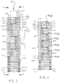
- Fig. 1 illustrates a linear DC motor in accordance with a parallel-connected embodiment of the present invention.
- Fig. 2 illustrates a linear DC motor in accordance with a series-connected embodiment.
- the DC motor of the present invention includes a primary along which a plurality of conductive segments A1, A2 VietnameseAn-1, An are arranged side-by-side. Conductive segments A1, A2 VietnameseAn-1, An are preferably mounted on a primary core (schematically shown in Figs. 3A-5B), and may be embedded in respective slots in the primary core. It is a primary advantage that the number of conductive segments and the length of the primary core are not limited, and may be conveniently extended to suit any particular application.
- conductive segments A1, A2....An include a corresponding pair of commutating pads CL1&CR1, CL2&CR....CLn-2&CRn-2, CLn-1&CRn-1, CLn&CRn, respectively.
- Commutating pads CL1-CRn may be integrally formed extensions of conductive segments Al-An.
- the DC motor of Figs. 1 and 2 also includes a secondary 10 adapted for electromotive movement with respect to the primary.
- the secondary 10 has at least one (but preferably more than one) magnetic poles P100 directed orthogonally to the primary conductive segments A1, A2....An.
- the magnetic poles are arranged in alternating polarities (N-S-N-S) as shown.
- the DC motor also includes a commutator for commutating the conductive segments A1, A2...An of the primary to maintain a linear induction drive of the secondary 10 as the secondary 10 moves along the length of the primary.
- the commutator comprises a plurality of commutating strips (or brushes) B101, B102....B107 mounted on opposing sides of the secondary 10.
- the commutating strips (or brushes) B101, B103...B107 grouped on the right side of secondary 10 maintain slidable conductive contact with a cluster of commutating pads on the same side, for example, commutating strip B101 is in contact with commutating pads CR1-CR4.
- commutating strips (or brushes) B102, B104...B106 grouped on the left side of secondary 10 maintain slidable conductive contact with a cluster of commutating pads on that side, for example, commutating strip B102 is in contact with commutating pads CL1-CL4.
- commutating strips (or brushes) B102, B104...B106 on the left hand side extend between points midway of the left sides of the magnets of secondary 10 and are spaced by a gap between each pair of commutating strips (or brushes) which should not be less than the width of one commutating pad CL1...CLn.
- the commutating strips (or brushes) B101, B103...B105, B107 on the right side are coextensive with the right side of the magnets of secondary 10 and are spaced by a gap between each pair of commutating strips (or brushes) which should not be less than the width of one commutating pad CR1...CRn.
- the commutating strips (or brushes) B101...B107 are equally spaced on both sides of the secondary 10 along the length, and the commutating strips (or brushes) B102, B104, B106 on the left side are arranged 180° out of phase with the commutating strips (or brushes) B101, B103, B105, B107 on the right side.
- each left side commutating strip B102, B104....B106 makes contact with a cluster of conductive segments A1....An via left commutating pads CL1....CLn
- each side commutating strip B101, B103...B105, B107 makes contact with a cluster of conductive segments A1...An via right commutating pads CR1...CRn.
- half of the adjacent conductive segments, contacting a commutating strip on the one side of the secondary are also contacting one commutating strip on the other side of the secondary, while half are contacting another adjacent commutating strip on the other side of the secondary.
- a cluster of adjacent conductive segments A1-A3 are connected between commutating strips (or brushes) B101 and B102, while another cluster of adjacent segments A5-A8 are connected between commutating strips (or brushes) B102 and B103.
- the arrangement continues in this manner for all commutating strips (or brushes) along the length of secondary 10, and for all conductive segments along the length of the primary.
- right and left sides of the secondary, right and left commutating strips (or brushes), etc. can be interchanged from right to left without affecting the operability of the invention. Therefore, those elements can be referred to as "one" side and “opposite” side, or "first commutating strips” (or brushes) and “second commutating strips” (or brushes), etc.
- Fig. 1 is a parallel-connected embodiment in which alternate right side commutating strips (or brushes), for example commutating strips (or brushes) B101 and B105, are connected to a source input of one polarity (+) while the other right side commutating strips (or brushes) B103 and B107 are connected to the other polarity (-).
- (+) and (-) terminals and conductors for the application of DC potential to the respective commutating strips (or brushes) constitute means for applying a DC potential of positive or negative polarity to the commutating strips (or brushes).
- the parallel-connected embodiment engenders multiple parallel current paths from each right side commutating strip B101, B103...B105, B107 to a left side commutating strip B102, B104...B106 and back to an adjacent right side commutating strip.
- the extent of each secondary magnetic pole must equal the extent of one commutating strip B101-B107 (180 electrical degrees in the illustrated embodiment).
- current return paths from the positive terminal (+) of the input source to the negative terminal (-) are provided by commutating strips (or brushes) B102, B103 etc. Current from the positive terminal flows from B101 through conductive segments A1-A4 into B102, thence through conductive segments A5-A8 into B103, whence it returns to the negative terminal.
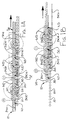
- Fig. 1A is an elevation view of the present invention corresponding to Fig. 1 except that the position of commutating strips (or brushes) B102, B104 and B106 is modified for clarity.
- commutating strips (or brushes) B102, B104 and B106 are shown as contacting the under sides of conductive segments A1, A2, etc., where, in practice, all commutating strips (or brushes) B101-B107 would contact the upper surfaces of conductive segments A1, A2, etc.
- No core for the primary is shown in Fig. 1A.
- the flux paths between adjacent magnetic poles of the secondary 10 are through the air.
- flux from the north pole N1 of the magnet M1 at the left end of secondary 10 threads downward past conductive segments A1-A4 and then loops upward to enter the south pole S2 of the adjacent magnet M2, as shown by the flux lines C.
- Flux from magnet M1 entering magnet M2 is returned from magnet M2 to magnet M1 as is shown by the flux lines D.
- Fig. 1A current in conductive segments A1-A4 is shown as flowing out of the plane of the paper, (i.e. from B101 to B102 in Fig. 1) and current in conductive segments A5-A12 is shown as flowing into the plane of the paper (from B102 and B104 through A5-A12 into B103).
- the magnetic fields surrounding conductive segments A1-A4 due to current flow are in counter clockwise direction and the field from magnet M1 to magnet M2 is also in the counter clockwise direction. Therefore, the field to the left of conductive segments A1-A4 is strengthened and the field to the right of conductive segments A1-A4 is weakened, generating a force on the secondary 10 that is directed to the right.
- the fields surrounding conductive segments A5-A12 due to current flow are in the clockwise direction.
- the fields of conductive segments A5-A8 due to current flow react with the flux entering magnet M2 from magnet M1 such that the fields to the right of conductive segments A5-A8 are weakened while the fields to the left of conductive segments A5-A8 are strengthened.
- the fields surrounding conductive segments A9-A12 due to current flow react with the flux entering magnet M2 from magnet M3 in the same manner as occurs with the fields of conductive segments A5-A8 and the flux from magnet M1, with the result that conductive segments A5-A12 also generate a force on secondary 10 that is directed to the right.
- Fig. 1B shows the disposition of the fields of the secondary 10 and of the conductors A1-An of the primary after movement of the secondary 10 to the right from the position shown in Fig. 1A.
- different conductive segments underlie the magnets of the secondary 10 and the directions of the currents in certain of the conductive segments is reversed, but the directions of the fields of the conductive segments of the primary and the magnets of the secondary are the same in Fig. 1B as in Fig. 1A. Therefore, the secondary will continue to be driven toward the right.
- Fig. 2 is an alternative series-connected embodiment wherein the extent of each secondary pole P100 equals one-half the extent of each secondary pole P100 of Fig. 1.
- Commutating strips (or brushes) B201 and B207 at opposite ends of the left side of secondary 10 are coextensive with the left sides of the poles at the opposite ends of the secondary 10.
- Commutating strips (or brushes) B202, B204 and B206 on the right side of the secondary 10 and commutating strips (or brushes) B203 and B205 on the left side of the secondary each extend the lengths of two adjacent poles of the secondary.
- any commutating strip on either side may be connected to any other commutating strip on the same side to complete a zig-zag series current path back and forth across the clusters of conductive segments A1-An, thereby serving to drive the primary.
- a zig-zag series current path will be created from commutating strip B201 across conductive segments A1-A4 to commutating strip B202, then back across conductive segments A5-A8 to commutating strip B203, and so on to commutating strip B207.
- the commutating angle is adjustable from a lagging angle to a leading angle by altering the dimensions and/or spacing of the commutating strips (or brushes) B101-B107 (B201-B208) or conductive segments A1-An, or the input source or secondary pole polarities.
- leading or lagging angle adjustments can be utilised to adjust the magnetomotive source between the primary and secondary. Therefore, the present invention is especially suitable to be used as the driving motor of a high speed electric train.
- the DC motor of the present invention includes magnetic poles P100 and correspondingly installed primary core M100 to constitute a closed magnetic circuit accommodating the conducting segments A1-An therebetween.
- Said primary core M100 may be implemented with multiple teeth type iron cores 301 having respective slots 302 between each two teeth iron cores 301 to receive respective conductive segments A1-An therein ( Figures 3A, 3B), or with a plane type coupling surface under the bottom side of the conducting segments (opposing to the side facing the magnetic poles P100 (Figs. 4A, 4B), or with magnetic poles P101 of the opposite polarity with respect to the magnetic poles P100 ( Figures 5A, 5B).
- Conductive segments A1-An are installed on the primary core (in any one of its implementations) by means known by those skilled in the art.
- a typical flux path (as explained above in reference to Figs. 1A, 1B) is from a north pole of the secondary 10 across the air gap separating the primary from the secondary 10, through the primary core M100 to an area underlying the adjacent south pole of the secondary 10, across the air gap between the primary and secondary, into the south pole of the adjacent magnet. From there, the magnetic circuit would be completed through air. If no core were provided for the primary, the magnetic circuits between adjacent magnetic would be completely through air.
- the conductive segments are electromagnetic coils which run substantially parallel to magnetic poles surface. Said conducting segments intersect with the motion direction at 90° angle (slighter larger or smaller angles). Said conducting segments may be implemented in different shapes (for instance, V shape) to reduce the thrust pulsation. In order to meet various requirements in different applications of the present invention, the coupling surface between conductive segments and magnetic poles may be implemented (in cross-sectional view) in linear, in V shape, U shape, W shape, M shape, and other modifications.
- FIG. 6 shows an example of the present invention as it applies to a DC rotary motor. From these figures it can be seen that the cylindrical rotor is provided with evenly distributed armature windings 610, and the two ends of these windings are connected to their respective commutating segments 607, 608.
- a first commutator is provided at one end of the machine and has at least two commutating strips (or brushes) 603, 604 (one for positive power and the other for negative), the commutating strips (or brushes) being separated by an angle of less than 180°.
- the angular distance between the two commutating strips (or brushes) 603 and 604 should be greater than one commutating segment 607 and 608 to prevent the windings from short circuiting.
- a second commutator is provided at the other end of the machine and has at least two commutating strips (or brushes) 605, 606 (one for positive power and the other for negative), the commutating strips (or brushes) being separated by an angle of less than 180°.
- the angular distance between the two commutating strips (or brushes) 605 and 606 should be greater than one commutating segment 607 and 608 to prevent the windings from short circuiting.
- the commutating strips (or brushes) 605 and 606 of the second commutator should be located 90° out of phase with the commutating strips (or brushes) 603 and 604 of the first commutator.
- the rotor may be of cylindrical, disk or cone type.
- Each conducting segment A1-An includes one of a plurality of coils, maintaining the principle of two spaced-apart ends of said conducting segments.
- Figs. 9 and 10 schematically show an example of a single coil and intercrossed coils, respectively. Spaced-apart ends of the coils are connected to the respective commutative pads CLn and CRn.
Landscapes
- Engineering & Computer Science (AREA)
- Power Engineering (AREA)
- Physics & Mathematics (AREA)
- Chemical & Material Sciences (AREA)
- Combustion & Propulsion (AREA)
- Electromagnetism (AREA)
- Dc Machiner (AREA)
Priority Applications (2)
| Application Number | Priority Date | Filing Date | Title |
|---|---|---|---|
| CN95106460A CN1055803C (zh) | 1995-06-14 | 1995-06-14 | 双侧交错导流非封闭型电枢绕组直流电动机 |
| EP96304334A EP0813288A1 (de) | 1995-06-14 | 1996-06-10 | Segmentierte Ankerwicklung für Gleichstrommotor |
Applications Claiming Priority (2)
| Application Number | Priority Date | Filing Date | Title |
|---|---|---|---|
| CN95106460A CN1055803C (zh) | 1995-06-14 | 1995-06-14 | 双侧交错导流非封闭型电枢绕组直流电动机 |
| EP96304334A EP0813288A1 (de) | 1995-06-14 | 1996-06-10 | Segmentierte Ankerwicklung für Gleichstrommotor |
Publications (1)
| Publication Number | Publication Date |
|---|---|
| EP0813288A1 true EP0813288A1 (de) | 1997-12-17 |
Family
ID=25743715
Family Applications (1)
| Application Number | Title | Priority Date | Filing Date |
|---|---|---|---|
| EP96304334A Withdrawn EP0813288A1 (de) | 1995-06-14 | 1996-06-10 | Segmentierte Ankerwicklung für Gleichstrommotor |
Country Status (2)
| Country | Link |
|---|---|
| EP (1) | EP0813288A1 (de) |
| CN (1) | CN1055803C (de) |
Families Citing this family (3)
| Publication number | Priority date | Publication date | Assignee | Title |
|---|---|---|---|---|
| CN102088238A (zh) * | 2010-12-30 | 2011-06-08 | 中国科学院等离子体物理研究所 | 直线电、机械比例转换器 |
| CN103187853B (zh) * | 2013-04-24 | 2016-08-24 | 宁波江东晟创工业产品设计有限公司 | 磁电动能连运装置 |
| CN110086318B (zh) * | 2019-04-25 | 2020-05-01 | 江苏利得尔电机有限公司 | 一种轨道交通用直线感应电机w型次级设计方法 |
Citations (4)
| Publication number | Priority date | Publication date | Assignee | Title |
|---|---|---|---|---|
| DE52130C (de) * | TH. L. WlLL-SON in Brooklyn, New-York, V. St. A | Dynamomaschine | ||
| US4185216A (en) * | 1978-03-29 | 1980-01-22 | Westinghouse Electric Corp. | Circumferentially-segmented magnet homopolar dynamoelectric machine |
| DE3315617A1 (de) * | 1982-06-01 | 1983-12-01 | Anorad Corp., 11788 Hauppauge, N.Y. | Linearmotor |
| EP0481774A2 (de) * | 1990-10-19 | 1992-04-22 | Tai-Her Yang | Zwei Richtungen leitende und zwei Enden aufweisende, nicht geschlossene Ankerwicklungen für Gleichstrommotor |
-
1995
- 1995-06-14 CN CN95106460A patent/CN1055803C/zh not_active Expired - Fee Related
-
1996
- 1996-06-10 EP EP96304334A patent/EP0813288A1/de not_active Withdrawn
Patent Citations (4)
| Publication number | Priority date | Publication date | Assignee | Title |
|---|---|---|---|---|
| DE52130C (de) * | TH. L. WlLL-SON in Brooklyn, New-York, V. St. A | Dynamomaschine | ||
| US4185216A (en) * | 1978-03-29 | 1980-01-22 | Westinghouse Electric Corp. | Circumferentially-segmented magnet homopolar dynamoelectric machine |
| DE3315617A1 (de) * | 1982-06-01 | 1983-12-01 | Anorad Corp., 11788 Hauppauge, N.Y. | Linearmotor |
| EP0481774A2 (de) * | 1990-10-19 | 1992-04-22 | Tai-Her Yang | Zwei Richtungen leitende und zwei Enden aufweisende, nicht geschlossene Ankerwicklungen für Gleichstrommotor |
Also Published As
| Publication number | Publication date |
|---|---|
| CN1138239A (zh) | 1996-12-18 |
| CN1055803C (zh) | 2000-08-23 |
Similar Documents
| Publication | Publication Date | Title |
|---|---|---|
| US4883999A (en) | Polyphase electronically commutated reluctance motor | |
| US4197488A (en) | Electrical machine | |
| US3891874A (en) | Compensated reciprocating electrodynamic machine | |
| EP1192700B1 (de) | Elektrische maschinen | |
| US11515771B2 (en) | Alternating-current driven, salient-teeth reluctance motor with concentrated windings | |
| US5202599A (en) | Electric motor | |
| WO2009056879A1 (en) | Permanent magnet reluctance machines | |
| US20150054373A1 (en) | Commutatorless and brushless dc machine with stationary armature and method of operating the same | |
| WO1989012347A1 (en) | Electric motor with iron-cored disk armature | |
| US4605873A (en) | Electromechanical machine | |
| US20030127931A1 (en) | Generator motor having inductor rotor | |
| US5894177A (en) | Segmented armature winding for a DC motor | |
| RU2091969C1 (ru) | Бесколлекторный двигатель постоянного тока | |
| EP0813288A1 (de) | Segmentierte Ankerwicklung für Gleichstrommotor | |
| RU2249904C2 (ru) | Электрическая машина с постоянными магнитами и энергосберегающим управлением | |
| US3239705A (en) | Electric rotating machine | |
| RU2089991C1 (ru) | Реактивный коммутируемый электродвигатель | |
| EP0431178A1 (de) | Synchronmaschine | |
| EP0481774B1 (de) | Zweirichtungsleitende, zwei Enden aufweisende, nicht geschlossene Ankerwicklungen für Gleichstrommotor | |
| US5317220A (en) | Linear DC motor | |
| RU2088028C1 (ru) | Двигатель ефименко (его варианты) | |
| EP0184418A2 (de) | Elektrische Gleichstromdrehmaschine | |
| JP7251212B2 (ja) | 巻線界磁型同期電動機 | |
| JPH09135545A (ja) | 電気モ−タ | |
| JP2005176463A (ja) | モータ |
Legal Events
| Date | Code | Title | Description |
|---|---|---|---|
| PUAI | Public reference made under article 153(3) epc to a published international application that has entered the european phase |
Free format text: ORIGINAL CODE: 0009012 |
|
| AK | Designated contracting states |
Kind code of ref document: A1 Designated state(s): AT CH DE ES FR GB IT LI NL SE |
|
| RBV | Designated contracting states (corrected) |
Designated state(s): AT CH DE ES FR GB IT LI NL SE |
|
| 17P | Request for examination filed |
Effective date: 19980615 |
|
| 17Q | First examination report despatched |
Effective date: 19991227 |
|
| GRAG | Despatch of communication of intention to grant |
Free format text: ORIGINAL CODE: EPIDOS AGRA |
|
| GRAG | Despatch of communication of intention to grant |
Free format text: ORIGINAL CODE: EPIDOS AGRA |
|
| GRAH | Despatch of communication of intention to grant a patent |
Free format text: ORIGINAL CODE: EPIDOS IGRA |
|
| STAA | Information on the status of an ep patent application or granted ep patent |
Free format text: STATUS: THE APPLICATION IS DEEMED TO BE WITHDRAWN |
|
| 18D | Application deemed to be withdrawn |
Effective date: 20010901 |