EP0818855A1 - Connector - Google Patents
Connector Download PDFInfo
- Publication number
- EP0818855A1 EP0818855A1 EP97111952A EP97111952A EP0818855A1 EP 0818855 A1 EP0818855 A1 EP 0818855A1 EP 97111952 A EP97111952 A EP 97111952A EP 97111952 A EP97111952 A EP 97111952A EP 0818855 A1 EP0818855 A1 EP 0818855A1
- Authority
- EP
- European Patent Office
- Prior art keywords
- cover
- protection tube
- lock portion
- corrugated tube
- lock
- Prior art date
- Legal status (The legal status is an assumption and is not a legal conclusion. Google has not performed a legal analysis and makes no representation as to the accuracy of the status listed.)
- Granted
Links
- 230000037431 insertion Effects 0.000 claims abstract description 16
- 238000003780 insertion Methods 0.000 claims abstract description 16
- 238000006073 displacement reaction Methods 0.000 claims abstract description 13
- 230000005489 elastic deformation Effects 0.000 claims description 8
- 238000010276 construction Methods 0.000 description 6
- 230000013011 mating Effects 0.000 description 5
- 230000015572 biosynthetic process Effects 0.000 description 3
- 238000005452 bending Methods 0.000 description 2
- 230000000694 effects Effects 0.000 description 2
- 230000001419 dependent effect Effects 0.000 description 1
- XLYOFNOQVPJJNP-UHFFFAOYSA-N water Substances O XLYOFNOQVPJJNP-UHFFFAOYSA-N 0.000 description 1
Images



Classifications
-
- H—ELECTRICITY
- H01—ELECTRIC ELEMENTS
- H01R—ELECTRICALLY-CONDUCTIVE CONNECTIONS; STRUCTURAL ASSOCIATIONS OF A PLURALITY OF MUTUALLY-INSULATED ELECTRICAL CONNECTING ELEMENTS; COUPLING DEVICES; CURRENT COLLECTORS
- H01R13/00—Details of coupling devices of the kinds covered by groups H01R12/70 or H01R24/00 - H01R33/00
- H01R13/58—Means for relieving strain on wire connection, e.g. cord grip, for avoiding loosening of connections between wires and terminals within a coupling device terminating a cable
- H01R13/582—Means for relieving strain on wire connection, e.g. cord grip, for avoiding loosening of connections between wires and terminals within a coupling device terminating a cable the cable being clamped between assembled parts of the housing
- H01R13/5825—Means for relieving strain on wire connection, e.g. cord grip, for avoiding loosening of connections between wires and terminals within a coupling device terminating a cable the cable being clamped between assembled parts of the housing the means comprising additional parts captured between housing parts and cable
-
- H—ELECTRICITY
- H01—ELECTRIC ELEMENTS
- H01R—ELECTRICALLY-CONDUCTIVE CONNECTIONS; STRUCTURAL ASSOCIATIONS OF A PLURALITY OF MUTUALLY-INSULATED ELECTRICAL CONNECTING ELEMENTS; COUPLING DEVICES; CURRENT COLLECTORS
- H01R13/00—Details of coupling devices of the kinds covered by groups H01R12/70 or H01R24/00 - H01R33/00
- H01R13/46—Bases; Cases
- H01R13/502—Bases; Cases composed of different pieces
- H01R13/506—Bases; Cases composed of different pieces assembled by snap action of the parts
-
- H—ELECTRICITY
- H02—GENERATION; CONVERSION OR DISTRIBUTION OF ELECTRIC POWER
- H02G—INSTALLATION OF ELECTRIC CABLES OR LINES, OR OF COMBINED OPTICAL AND ELECTRIC CABLES OR LINES
- H02G3/00—Installations of electric cables or lines or protective tubing therefor in or on buildings, equivalent structures or vehicles
- H02G3/02—Details
- H02G3/06—Joints for connecting lengths of protective tubing or channels, to each other or to casings, e.g. to distribution boxes; Ensuring electrical continuity in the joint
- H02G3/0616—Joints for connecting tubing to casing
- H02G3/0691—Fixing tubing to casing by auxiliary means co-operating with indentations of the tubing, e.g. with tubing-convolutions
-
- H—ELECTRICITY
- H01—ELECTRIC ELEMENTS
- H01R—ELECTRICALLY-CONDUCTIVE CONNECTIONS; STRUCTURAL ASSOCIATIONS OF A PLURALITY OF MUTUALLY-INSULATED ELECTRICAL CONNECTING ELEMENTS; COUPLING DEVICES; CURRENT COLLECTORS
- H01R13/00—Details of coupling devices of the kinds covered by groups H01R12/70 or H01R24/00 - H01R33/00
- H01R13/58—Means for relieving strain on wire connection, e.g. cord grip, for avoiding loosening of connections between wires and terminals within a coupling device terminating a cable
- H01R13/582—Means for relieving strain on wire connection, e.g. cord grip, for avoiding loosening of connections between wires and terminals within a coupling device terminating a cable the cable being clamped between assembled parts of the housing
- H01R13/5829—Means for relieving strain on wire connection, e.g. cord grip, for avoiding loosening of connections between wires and terminals within a coupling device terminating a cable the cable being clamped between assembled parts of the housing the clamping part being flexibly or hingedly connected to the housing
Definitions
- the present invention relates to a connector which protects wires coming out of a connector housing by a cover.
- FIG. 7 A connector of this type is shown in FIG. 7.
- This connector is comprised of a connector housing 1 for accommodating terminals (not shown) inside, wires 2 coming out of the connector housing 1 through its rear end surface, a protection tube 3 surrounding the wires 2, and a tubular cover 4 to be mounted on a rear end portion of the connector housing 1 to surround exposed portions of the wires 2 between the connector housing 1 and the protection tube 3.
- a loose displacement of the protection tube 3 along its longitudinal direction is restricted by locking the protection tube 3 in the cover 4.
- the cover 4 is formed such that two half pieces 4a having a semicylindrical configuration are connected via a hinge 4b. At a front part of the cover 4 is formed an engaging portion 4c to be engaged with the connector housing 1. At a rear part of the cover 4 is formed a lock portion 4d which is corrugated to be engageable with circumferentially extending recesses and projections formed in the outer surface of the protection tube 3.
- the above prior art connector has a poor operability because the protection tube 3 needs to be positioned with respect to the lock portion 4d when being mounted on the cover 4.
- the present invention was developed in view of the above problem and an object thereof is to improve operability when a protection tube is mounted on a cover.
- a connector in which wires come out of a connector housing through a end surface, a substantially tubular cover is mounted on an end portion of the connector housing and a protection tube is mounted on an end portion of the cover, wherein the cover is provided with at least one elastically deformable lock portion, so that the elastic deformation of the lock portion permits the insertion of a portion of the protection tube into the cover along its longitudinal direction and brings the lock portion into engagement with the protection tube to hold the protection tube while restricting its loose displacement along its longitudinal and/or radial direction.
- the protection tube when the protection tube is inserted into the tubular cover substantially along its longitudinal direction, the insertion of the protection tube is permitted by the elastic deformation of the lock portion.
- the lock engages the outer surface of the protection tube, with the result that the protection tube is mounted in such a manner that its loose displacement with respect to the cover along its longitudinal and/or radial direction is restricted.
- the inventive connector has a good operability because the protection tube can be mounted on the cover only by being inserted.
- the lock portion is formed such that its free ends extend obliquely inward along the insertion direction of the protection tube from its supported end on the inner surface of the cover.
- the lock portion is formed such that its free ends extend obliquely inward along the insertion direction of the protection tube from its supported end on the inner surface of the cover, it can smoothly undergo an elastic deformation in its outward direction as the protection tube is inserted.
- a force acts on the lock portion to deform inward, thereby being pressed against the outer surface of the protection tube. Accordingly, the lock portion is not disengaged from the protection tube.
- the lock portion can make the insertion of the protection tube smoother and, at the same time, prevent the disengagement of the protection tube.
- the lock portion is formed with cover engaging means for engaging the protection tube, wherein the cover engaging means preferably comprises at least one projection and at least one recess interacting with at least one groove and at least one projection of the protection tube, respectively.
- cover engaging means mating to the protection tube are provided in the cover.
- At least one lock portion comprises an inwardly projecting portion having both ends supported on the cover, wherein the inwardly projecting portion is preferably shaped like a triangle or an embossment.
- the lock portion comprises an arcuate portion, having preferably a radius of curvature substantially corresponding to that of the protection tube, in particular of one or more grooves thereof, wherein the arcuate portion is preferably substantially concentrically arranged with an opening of the cover, through which the protection tube is inserted into the cover.
- the protection tube substantially surrounding the wires is mounted on the end portion of the cover to substantially protect the portions of the wires coming out of the connector housing by the cover and the protection tube.
- the lock portion is brought into engagement with the outer surface of the protection tube.
- the lock portion is formed such that there is formed a drain hole in the cover.
- the cover comprises two half pieces being lockable with each other by locking means.
- the two half pieces have substantially the same configuration in rotationally inverted positions about an axis.
- a connector in which wires come out of a connector housing through its rear end surface, a tubular cover is mounted on a rear end portion of the connector housing to surround the wires and a protection tube surrounding the wires is mounted a rear end portion of the cover to protect the portions of the wires coming out of the connector housing by the cover and the protection tube, wherein the cover is provided with an elastically deformable lock portion, so that the elastic deformation of the lock portion permits the insertion of the protection tube into the cover along its longitudinal direction and brings the lock portion into engagement with the outer surface of the protection tube to hold the protection tube while restricting its loose displacement along its longitudinal direction.
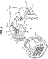
- a connector according to this embodiment is comprised of a connector housing 10 accommodating terminals (not shown) inside, a cover 20 to be mounted on a rear end portion of the connector housing 10, and a corrugated tube 30 (protection tube) to be mounted on the cover 20.
- mount grooves 11 for mounting the cover 20.
- a plurality of wires connected with the terminals come out of the connector housing 10 through its rear end surface.
- the corrugated tube 30 is preferably mounted in advance to movably surround the wires W coming out of the connector housing 10 along its longitudinal direction.
- the corrugated tube 30 has circumferentially extending grooves 31 and projections 32 alternately formed in its outer surface, and is deformable in such a manner as to curve its longitudinal axis. By being surrounded by such a corrugated tube 30, the wires W are protected without being exposed. Lock portions 27 of the cover 20 to be described later are to be engaged with the grooves 31 and the projections 32 of the corrugated tube 30.
- the cover 20 is comprised of a pair of half pieces 20A having preferably a substantially semicylindrical configuration.
- the pair of half pieces 20A When being mounted on the connector housing 10, the pair of half pieces 20A are assembled into a tubular form as a whole and protect the portions of the wires W coming out of the connector housing 10 by substantially surrounding them.
- the pair of half pieces 20A have preferably the same configuration and are assembled in rotationally inverted positions about an axis.
- mount portions 22 which are engageable with the corresponding mount grooves 11 of the connector housing 10.
- a preferably semicircular notch 23 used for the insertion of the corrugated tube 30.
- the shape of the notch or opening 23 is adapted or corresponds to the shape of the corrugated tube 30.
- a lock projection 24 and a lock portion 25 are formed on each of the contact edges of the half pieces 20A which are to abut against each other.
- the lock projection 24 and the lock portion 25 of one half piece 20A are engaged with their counterparts of the mating half piece 20A.
- engaging projections 26A, 26B are formed on one contact edge of the half piece 20A for holding the other contact edge of the mating half piece 20A from opposite sides in inward and outward directions.
- the half pieces 20A are locked in their tubular state by the engagement of the lock projections 24 and the lock portions 25 and by the engagement of the engaging projections 26A, 26B and the contact edges of the mating half pieces 20A.
- Each half piece 20A is formed with the lock portion 27 for holding the corrugated tube 30 mounted.
- the lock portion 27 is formed such that its free end extends from its supported end on the inner surface of the half piece 20A so as to be elastically deformable in radial and/or axial directions.
- the lock portion 27 extends obliquely inward toward the front from a position near its rear end (an end where the corrugated tube 30 is inserted).
- At the free end of the lock portion 27 are formed at least one projection 28 and/or at least one recess 29 to be engaged with the groove 31 and the projections 32 of the corrugated tube 30, wherein the projection 28 and/or the recess 29 are preferably circumferentially provided. When they are engaged, the projections 28 and the recess 29 are locked along the longitudinal direction of the corrugated tube 30, thereby restricting a loose displacement of the corrugated tube 30 with respect to the cover 20 along its longitudinal direction.
- an opening is left in one side surface of the half piece 20A. This opening acts as a drain hole 21 for draining water within the cover 20 when the pair of half pieces 20A are assembled into a tubular form.
- the wires W are caused to come out of the connector housing 10 through its rear end surface and surrounded by the corrugated tube 30.
- the cover 20 is first mounted on the connector housing 10.
- the corrugate tube 30 is positioned behind the cover 20.
- the lock portions 25 are elastically deformed to be engaged with the lock projections 24, and the engaging projections 26A, 26B hold the contact edges of the mating half pieces 20A.
- the pair of half pieces 20A are assembled into the tubular cover 20 and, at the same time, the cover 20 is mounted on the rear end portion of the connector housing 10.
- the mounted cover 20 protects the portions of the wires W coming out of the connector housing 10 by surrounding them.
- the corrugated tube 30 is fitted to the cover 20. This operation is done by moving the corrugated tube 30 forward along its longitudinal direction and inserting it into the cover 20 through the notches 23 in the rear end surface of the cover 20. Then, a pair of lock portions 27 inside the cover 20 are elastically deformed outward by being pressed by the outer surface of the corrugated tube 30 as shown in FIG. 3, with the result that the projections 28 of the lock portions 27 move over the projection 32 of the corrugated tube 30. In other words, the corrugated tube 30 can be smoothly inserted by the elastic deformation of the lock portions 27. The insertion is stopped when the corrugated tube 30 reaches a proper lock position.
- the lock portions 27 engage the outer surface of the corrugated tube 30 due to their elastic restoring forces. In this way, the mounting of the corrugated tube 30 is completed. In this state, the projections 28 and the recesses 29 of the lock portions 27 are locked with the groove 31 and the projection 32 of the corrugated tube 30 along its longitudinal direction, with the result that the corrugated tube 30 is held in such a manner that its loose displacement with respect to the cover 20 along its longitudinal direction is restricted.
- the wires W are surrounded by any one of the connector housing 10, the cover 20 and the corrugated tube 30 over their substantially entire length so as to not be exposed to the outside.
- the corrugated tube 30 can be mounted only by moving the corrugated tube 30 along its longitudinal direction and inserting it into the cover 20. Accordingly, a cumbersome operation of positioning the corrugated tube 30 with respect to the lock portions 27 in advance can be omitted, thereby improving operability.
- This connector can be more easily assembled as compared to a connector in which a cover is mounted on a connector housing after a corrugated tube is partly locked with a lock portion so as not to displace.
- each lock portion 27 is formed such that its free end extends preferably obliquely inward along the insertion direction of the corrugated tube 30 from its supported end on the inner surface of the cover 20. Accordingly, the lock portions 27 can smoothly undergo an elastic deformation in their outward directions by being pressed by the outer surface of the corrugated tube 30 being inserted. Thus, the corrugated tube 30 can be satisfactorily easily inserted.
- the lock portion 27 may extend vertically and be deflectable along an axial direction and a radial direction, so as to allow the insertion or fitting of the corrugated tube 30 into the cover 20. Furthermore there might be provided two or more lock portions 27 in the cover 20.
- the projection 32 of the corrugated tube 30 presses the projections 28 of the lock portions 27 along the longitudinal direction of the corrugated tube 30, with the result that a force acts on the lock portions to deform them in their inward directions. Accordingly, the projections 32 and 28 cannot be disengaged and the corrugated tube 30 cannot move in its withdrawal direction.
- the corrugated tube 30 can be more smoothly inserted and the disengagement thereof can be securely prevented.
- the cover 20 is formed by assembling the pair of half pieces 20A having the same configuration in rotationally inverted positions about an axis. Accordingly, as compared to a connector in which a cover is formed by assembling two types of parts having different configurations, production costs can be reduced and storage and handling can be made easier.
- the openings left in the side walls of the cover 20 after the formation of the lock portions 27 can be utilized as drain holes 21, as compared to a case where such openings and drain holes are separately formed, a total open area of the cover 20 is smaller. Thus, the strength of the cover 20 can be enhanced.
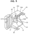
- the second embodiment differs from the first embodiment in the construction of the lock portions. Since the other constructions are similar to those of the first embodiment, no description is given on such constructions, and action and effects thereof by identifying them by the same reference numerals.
- a lock portion of the second embodiment is, similar to the lock portion 27 of the first embodiment, formed such that its free end extends preferably obliquely inward toward the front from its supported end on the inner surface of the half piece 20A of the cover 20.
- On the rear end of the lock portion 40 is formed a plate-like projection 41 projecting inward at an angle different from 0° or 180°, preferably at a substantially right angle to the longitudinal direction of the half piece 20A.
- an arcuate portion 42 having the substantially same radius of curvature as the grooves 31 of the corrugated tube 30 (not shown in FIG. 5).
- the arcuate portions 42 are preferably concentrically arranged with a substantially circular opening or notch 23 formed in the rear end surface of the cover 20.
- the projection 41 is preferably provided on a tongue-shaped portion of the cover 20, projecting inwardly at an angle different from 0° or 180° with respect to the wall(s) of the cover 20.
- the corrugated tube 30 When the corrugated tube 30 is inserted into the cover 20 provided with such lock portions 40, the insertion thereof can be smoothly performed by the elastic deformation of the lock portions 40.
- the projection 32 of the inserted corrugated tube 30 is locked with the projections 41 along its longitudinal direction, thereby restricting a loose displacement of the corrugated tube 30 along its longitudinal direction.
- the arcuate portions 42 of the projections 41 are engaged with the groove 31, thereby restricting a loose displacement of the corrugated tube 30 with respect to the cover 20 along radial directions, particularly along vertical direction of FIG. 5. There is, accordingly, no likelihood that the corrugate tube 30 is radially displaced and disengaged from the locking portions 40.
- the corrugated tube 30 can be securely held mounted on the cover 20.
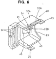
- the third embodiment differs from the first embodiment in the construction of the lock portions. Since the other constructions are similar to those of the first embodiment, no description is given on such constructions, and action and effects thereof by identifying them by the same reference numerals.
- a lock portion of the third embodiment is made elastically deformable with both ends thereof supported.
- the lock portion 45 is narrow along forward and backward directions (a direction parallel to the insertion direction of the corrugated tube 30); has its front and rear ends supported on the half piece 20A of the cover 20; and projects inwardly from the inner surface of the half piece 20A along a moderately curved arc.
- a projection 46 projecting inward is formed preferably in a substantially middle position of the lock portion 45 along forward and backward directions. The projections 46 are engaged with the groove 31 of the corrugated tube 30 (not shown in FIG. 6) to be locked with the projection 32 along the longitudinal direction of the corrugated tube 30, thereby restricting a loose displacement of the corrugated tube 30 with respect to the cover 20 along its longitudinal direction.
- the lock portion 45 Since the lock portion 45 is supported at its both ends according to the third embodiment, a larger force is required to deform it. Accordingly, even upon a force acting in the withdrawal direction of the corrugated tube 30 or in a transverse direction thereof (direction in which the lock portion 45 is deformed), the lock portion 45 is unlikely to be deformed. Thus, the displacement of the corrugated tube 30 in its withdrawal and/or transverse directions can be securely hindered.
Landscapes
- Engineering & Computer Science (AREA)
- Architecture (AREA)
- Civil Engineering (AREA)
- Structural Engineering (AREA)
- Details Of Connecting Devices For Male And Female Coupling (AREA)
- Details Of Indoor Wiring (AREA)
- Connector Housings Or Holding Contact Members (AREA)
Abstract
Description
wherein the cover is provided with at least one elastically deformable lock portion, so that the elastic deformation of the lock portion permits the insertion of a portion of the protection tube into the cover along its longitudinal direction and brings the lock portion into engagement with the protection tube to hold the protection tube while restricting its loose displacement along its longitudinal and/or radial direction.
wherein the cover is provided with an elastically deformable lock portion, so that the elastic deformation of the lock portion permits the insertion of the protection tube into the cover along its longitudinal direction and brings the lock portion into engagement with the outer surface of the protection tube to hold the protection tube while restricting its loose displacement along its longitudinal direction.
- W
- Wire
- 10
- Connector Housing
- 20
- Housing
- 27
- Lock Portion
- 30
- Corrugated Tube (Protection Tube)
- 40, 45
- Lock Portion
Claims (10)
- A connector in which wires come out of a connector housing (10) through an end surface, a substantially tubular cover (20) is mounted on an end portion of the connector housing (10) and a protection tube (30) is mounted on an end portion of the cover (20),
wherein the cover (20) is provided with at least one elastically deformable lock portion (27; 40; 45), so that the elastic deformation of the lock portion (27; 40; 45) permits the insertion of a portion of the protection tube (30) into the cover (20) along its longitudinal direction and brings the lock portion (27; 40; 45) into engagement with the protection tube (30) to hold the protection tube (30) while restricting its loose displacement along its longitudinal and/or radial direction. - A connector according to claim 1, wherein the lock portion (27; 40; 45) is formed such that its free ends extend obliquely inward along the insertion direction of the protection tube (30) from its supported end on the inner surface of the cover (20).
- A connector according to one or more of the preceding claims, wherein at least one lock portion (45) comprises an inwardly projecting portion having both ends supported on the cover (20), wherein the inwardly projecting portion is preferably shaped like a triangle or an embossment.
- A connector according to one or more of the preceding claims, wherein the lock portion (41) comprises an arcuate portion (42), having preferably a radius of curvature substantially corresponding to that of the protection tube (30), in particular of one or more grooves (31) thereof.
- A connector according to claim 4, wherein the arcuate portion (42) is substantially concentrically arranged with an opening (23) of the cover (20), through which the protection tube (30) is inserted into the cover (20).
- A connector according to one or more of the preceding claims, wherein the protection tube (30) substantially surrounding the wires (W) is mounted on the end portion of the cover (20) to substantially protect the portions of the wires (W) coming out of the connector housing (10) by the cover (20) and the protection tube (30).
- A connector according to one or more of the preceding claims, wherein the lock portion (27; 40; 45) is brought into engagement with the outer surface of the protection tube (30).
- A connector according to one or more of the preceding claims, wherein the lock portion (27; 40; 45) is formed such that there is formed a drain hole (21; 47) in the cover (20).
- A connector according to one or more of the preceding claims, wherein the cover (20) comprises two half pieces (20A) being lockable with each other by locking means (24; 25).
- A connector according to claim 9, wherein the two half pieces (20A) have substantially the same configuration in rotationally inverted positions about an axis.
Priority Applications (1)
| Application Number | Priority Date | Filing Date | Title |
|---|---|---|---|
| EP00107902A EP1022814A3 (en) | 1996-07-12 | 1997-07-14 | Connector |
Applications Claiming Priority (3)
| Application Number | Priority Date | Filing Date | Title |
|---|---|---|---|
| JP18355296 | 1996-07-12 | ||
| JP8183552A JPH1027646A (en) | 1996-07-12 | 1996-07-12 | Connector |
| JP183552/96 | 1996-07-12 |
Related Child Applications (1)
| Application Number | Title | Priority Date | Filing Date |
|---|---|---|---|
| EP00107902A Division EP1022814A3 (en) | 1996-07-12 | 1997-07-14 | Connector |
Publications (2)
| Publication Number | Publication Date |
|---|---|
| EP0818855A1 true EP0818855A1 (en) | 1998-01-14 |
| EP0818855B1 EP0818855B1 (en) | 2001-06-13 |
Family
ID=16137809
Family Applications (2)
| Application Number | Title | Priority Date | Filing Date |
|---|---|---|---|
| EP00107902A Withdrawn EP1022814A3 (en) | 1996-07-12 | 1997-07-14 | Connector |
| EP97111952A Expired - Lifetime EP0818855B1 (en) | 1996-07-12 | 1997-07-14 | Connector |
Family Applications Before (1)
| Application Number | Title | Priority Date | Filing Date |
|---|---|---|---|
| EP00107902A Withdrawn EP1022814A3 (en) | 1996-07-12 | 1997-07-14 | Connector |
Country Status (5)
| Country | Link |
|---|---|
| US (1) | US5967830A (en) |
| EP (2) | EP1022814A3 (en) |
| JP (1) | JPH1027646A (en) |
| CN (1) | CN1184349A (en) |
| DE (1) | DE69705170T2 (en) |
Cited By (9)
| Publication number | Priority date | Publication date | Assignee | Title |
|---|---|---|---|---|
| EP1158548A1 (en) * | 2000-05-24 | 2001-11-28 | Aupem Sefli | Cable lead-through device |
| EP1170828A1 (en) | 2000-07-06 | 2002-01-09 | Yazaki Corporation | Protective cover |
| EP1770829A1 (en) * | 2005-09-30 | 2007-04-04 | Yazaki Corporation | Connector |
| US7713070B2 (en) | 2005-04-11 | 2010-05-11 | Autonetwork Technologies, Ltd. | Electric connection box |
| EP2781395A1 (en) * | 2013-03-21 | 2014-09-24 | Delphi International Operations Luxembourg S.à r.l. | Cable connector and connector assembly process |
| EP2816879A3 (en) * | 2013-06-21 | 2015-04-01 | Wieland Electric GmbH | Lead connector |
| EP3200288A1 (en) * | 2016-01-29 | 2017-08-02 | Wago Verwaltungsgesellschaft mbH | Housing of an electrical connector housing or for mounting an electrical connector |
| WO2017198365A1 (en) * | 2016-05-17 | 2017-11-23 | Schlemmer Gmbh | Receiving device and cable harness |
| EP3956958A4 (en) * | 2019-04-18 | 2022-04-06 | Bimed Teknik Aletler Sanayi ve Ticaret Anonim Sirketi | Conduit draining and protecting muff |
Families Citing this family (40)
| Publication number | Priority date | Publication date | Assignee | Title |
|---|---|---|---|---|
| US6558185B1 (en) * | 2000-05-02 | 2003-05-06 | Dekko Engineering, Inc. | Jumper cable plug |
| JP3755654B2 (en) * | 2002-04-17 | 2006-03-15 | タイコエレクトロニクスアンプ株式会社 | Electrical connector assembly and wire protector |
| JP4062146B2 (en) * | 2003-03-25 | 2008-03-19 | 住友電装株式会社 | Connector and wire cover |
| JP4096255B2 (en) * | 2003-06-24 | 2008-06-04 | 住友電装株式会社 | Wire cover |
| DE102004024484A1 (en) * | 2004-05-14 | 2005-12-08 | Murrplastik Systemtechnik Gmbh | Electrical wiring system, has plastic fixing socket with two half shells partially encompassing terminal coupling and protecting hose, where coupling is fixed at hose in its longitudinal direction by socket |
| DE102004026346A1 (en) * | 2004-05-26 | 2005-12-15 | Murrplastik Systemtechnik Gmbh | Screw connection device for coupling corrugated protective sleeve for cable connection to electrical apparatus, has one cable inserted into connection channel and connected to coupling for joining to second cable |
| JP4520315B2 (en) * | 2005-01-21 | 2010-08-04 | タイコエレクトロニクスジャパン合同会社 | Wire cover for connector |
| JP4765818B2 (en) * | 2006-08-02 | 2011-09-07 | 住友電装株式会社 | Wire cover |
| JP2008052918A (en) * | 2006-08-22 | 2008-03-06 | Sumitomo Wiring Syst Ltd | Connector with a cover |
| JP4930177B2 (en) * | 2007-05-07 | 2012-05-16 | 住友電装株式会社 | Protector |
| JP5084019B2 (en) * | 2007-08-21 | 2012-11-28 | 矢崎総業株式会社 | Wire harness protector |
| DE102007053722B4 (en) * | 2007-11-10 | 2011-08-25 | Amphenol-Tuchel Electronics GmbH, 74080 | Hermaphroditic connector |
| US7927150B2 (en) * | 2008-10-23 | 2011-04-19 | Tyco Electronics Corporation | Connectors including spring tabs for holding a contact module |
| JP4898855B2 (en) * | 2009-02-04 | 2012-03-21 | 矢崎総業株式会社 | connector |
| JP5588773B2 (en) * | 2010-07-28 | 2014-09-10 | タイコエレクトロニクスジャパン合同会社 | Wire cover, electrical connector |
| JP5598384B2 (en) * | 2011-03-04 | 2014-10-01 | 住友電装株式会社 | connector |
| EP2511988B1 (en) * | 2011-04-12 | 2014-11-19 | Siemens Aktiengesellschaft | Line seating with torsion relief |
| US9287652B2 (en) * | 2011-08-24 | 2016-03-15 | Yazaki Corporation | Cover-fitted connector |
| JP5723726B2 (en) * | 2011-08-24 | 2015-05-27 | 矢崎総業株式会社 | Connector with cover |
| JP5686077B2 (en) | 2011-09-10 | 2015-03-18 | 住友電装株式会社 | connector |
| US8545257B2 (en) * | 2011-09-20 | 2013-10-01 | Jason Pedruzzi | Integrated banding connector |
| JP5854331B2 (en) * | 2012-07-20 | 2016-02-09 | 住友電装株式会社 | connector |
| JP6055260B2 (en) * | 2012-10-05 | 2016-12-27 | 矢崎総業株式会社 | Charging connector |
| DE102014109270B4 (en) | 2014-07-02 | 2023-11-16 | Lisa Dräxlmaier GmbH | Cable fixation, plug with a cable fixation and method for fixing an electrical cable to a plug |
| CN105281277A (en) * | 2015-11-20 | 2016-01-27 | 中天科技海缆有限公司 | A submarine cable center positioning protection device |
| JP6324364B2 (en) * | 2015-12-11 | 2018-05-16 | 矢崎総業株式会社 | Connector wire cover |
| CN106450907B (en) * | 2016-12-06 | 2019-02-12 | 安徽江淮汽车集团股份有限公司 | A kind of automobile inserting components tail folder |
| CN106515620B (en) * | 2016-12-06 | 2018-09-11 | 安徽江淮汽车集团股份有限公司 | A kind of automobile inserting components tail folder |
| JP6798402B2 (en) * | 2017-04-12 | 2020-12-09 | 住友電装株式会社 | Wire harness with protector |
| US9780483B1 (en) * | 2017-04-27 | 2017-10-03 | Wesley Astor Goulbourne | Modular strain relief assembly |
| US10020599B1 (en) * | 2017-07-12 | 2018-07-10 | Delphi Technologies, Inc. | Connector back shell assembly |
| CN107611868A (en) * | 2017-09-27 | 2018-01-19 | 国网山西省电力公司检修分公司 | Fast demountable type cable protective sleeve |
| US10290970B1 (en) * | 2018-02-08 | 2019-05-14 | Delphi Technologies, Llc | Connector with strain relief device |
| JP6735313B2 (en) * | 2018-05-22 | 2020-08-05 | 矢崎総業株式会社 | Closure body holding structure and electric wire with connector |
| KR102056934B1 (en) * | 2018-09-14 | 2020-01-22 | 한국단자공업 주식회사 | Assembly of shield shell and wire and high voltage connector using the same |
| CN109818273B (en) * | 2019-01-31 | 2020-06-30 | 国网浙江宁海县供电有限公司 | A relay protection device |
| JP6883595B2 (en) * | 2019-01-31 | 2021-06-09 | 矢崎総業株式会社 | Protective tube connection structure |
| US11557854B2 (en) * | 2021-04-09 | 2023-01-17 | Webasto Charging Systems, Inc. | Electric cable assembly |
| CN214754556U (en) * | 2021-05-09 | 2021-11-16 | 东莞市万旅电器有限公司 | Socket structure |
| US20230411873A1 (en) | 2022-06-17 | 2023-12-21 | Hubbell Incorporated | Connector cover assemblies |
Citations (4)
| Publication number | Priority date | Publication date | Assignee | Title |
|---|---|---|---|---|
| AT335001B (en) * | 1975-02-03 | 1977-02-25 | Goeransson Bengt S | COUPLING DEVICE |
| EP0080813A1 (en) * | 1981-11-20 | 1983-06-08 | AMP INCORPORATED (a New Jersey corporation) | Hermaphroditic back shell cover |
| US5422437A (en) * | 1993-04-16 | 1995-06-06 | Hubbell Incorporated | Electrical connector assembly |
| US5444182A (en) * | 1990-11-21 | 1995-08-22 | Sumitomo Wiring Systems | Wire harness connector cover |
Family Cites Families (6)
| Publication number | Priority date | Publication date | Assignee | Title |
|---|---|---|---|---|
| JP2557399B2 (en) * | 1987-04-28 | 1996-11-27 | 北川工業株式会社 | Corrugated pipe fitting |
| JPH07105249B2 (en) * | 1989-03-01 | 1995-11-13 | 矢崎総業株式会社 | Electrical connector |
| US5080614A (en) * | 1991-04-23 | 1992-01-14 | Harold Utgaren | Quick connect electrical plug |
| JP2570126Y2 (en) * | 1992-10-23 | 1998-05-06 | 住友電装株式会社 | Insulator for terminal connection |
| US5762520A (en) * | 1996-04-30 | 1998-06-09 | The Whitaker Corporation | Hermaphroditic wire cover |
| US5839911A (en) * | 1997-01-24 | 1998-11-24 | The Whitaker Corporation | Adjustable and releasable strain relief |
-
1996
- 1996-07-12 JP JP8183552A patent/JPH1027646A/en active Pending
-
1997
- 1997-07-10 CN CN97114563A patent/CN1184349A/en active Pending
- 1997-07-11 US US08/890,815 patent/US5967830A/en not_active Expired - Fee Related
- 1997-07-14 EP EP00107902A patent/EP1022814A3/en not_active Withdrawn
- 1997-07-14 DE DE69705170T patent/DE69705170T2/en not_active Expired - Fee Related
- 1997-07-14 EP EP97111952A patent/EP0818855B1/en not_active Expired - Lifetime
Patent Citations (4)
| Publication number | Priority date | Publication date | Assignee | Title |
|---|---|---|---|---|
| AT335001B (en) * | 1975-02-03 | 1977-02-25 | Goeransson Bengt S | COUPLING DEVICE |
| EP0080813A1 (en) * | 1981-11-20 | 1983-06-08 | AMP INCORPORATED (a New Jersey corporation) | Hermaphroditic back shell cover |
| US5444182A (en) * | 1990-11-21 | 1995-08-22 | Sumitomo Wiring Systems | Wire harness connector cover |
| US5422437A (en) * | 1993-04-16 | 1995-06-06 | Hubbell Incorporated | Electrical connector assembly |
Cited By (17)
| Publication number | Priority date | Publication date | Assignee | Title |
|---|---|---|---|---|
| EP1158548A1 (en) * | 2000-05-24 | 2001-11-28 | Aupem Sefli | Cable lead-through device |
| FR2809530A1 (en) * | 2000-05-24 | 2001-11-30 | Aupem Sefli | DEVICE FOR PASSING A CABLE |
| EP1170828A1 (en) | 2000-07-06 | 2002-01-09 | Yazaki Corporation | Protective cover |
| US6568967B2 (en) | 2000-07-06 | 2003-05-27 | Yazaki Corporation | Protective cover |
| US7713070B2 (en) | 2005-04-11 | 2010-05-11 | Autonetwork Technologies, Ltd. | Electric connection box |
| EP1770829A1 (en) * | 2005-09-30 | 2007-04-04 | Yazaki Corporation | Connector |
| US7381072B2 (en) | 2005-09-30 | 2008-06-03 | Yazaki Corporation | Connector having a strain relief structure |
| EP2781395A1 (en) * | 2013-03-21 | 2014-09-24 | Delphi International Operations Luxembourg S.à r.l. | Cable connector and connector assembly process |
| EP2816879A3 (en) * | 2013-06-21 | 2015-04-01 | Wieland Electric GmbH | Lead connector |
| EP3200288A1 (en) * | 2016-01-29 | 2017-08-02 | Wago Verwaltungsgesellschaft mbH | Housing of an electrical connector housing or for mounting an electrical connector |
| WO2017198365A1 (en) * | 2016-05-17 | 2017-11-23 | Schlemmer Gmbh | Receiving device and cable harness |
| CN109155509A (en) * | 2016-05-17 | 2019-01-04 | 德国诗兰姆有限及两合公司 | Reception device and cable bundle |
| EP3459148A1 (en) * | 2016-05-17 | 2019-03-27 | Schlemmer GmbH | Receiving device and cable harness |
| RU2698798C1 (en) * | 2016-05-17 | 2019-08-30 | Шлеммер Гмбх | Receiving device and cable harness |
| US10707660B2 (en) | 2016-05-17 | 2020-07-07 | Schlemmer Gmbh | Receiving device and cable harness |
| CN109155509B (en) * | 2016-05-17 | 2021-02-26 | 德国诗兰姆有限及两合公司 | Receivers and Cable Harnesses |
| EP3956958A4 (en) * | 2019-04-18 | 2022-04-06 | Bimed Teknik Aletler Sanayi ve Ticaret Anonim Sirketi | Conduit draining and protecting muff |
Also Published As
| Publication number | Publication date |
|---|---|
| US5967830A (en) | 1999-10-19 |
| EP1022814A3 (en) | 2000-09-06 |
| CN1184349A (en) | 1998-06-10 |
| DE69705170D1 (en) | 2001-07-19 |
| EP0818855B1 (en) | 2001-06-13 |
| DE69705170T2 (en) | 2001-11-22 |
| JPH1027646A (en) | 1998-01-27 |
| EP1022814A2 (en) | 2000-07-26 |
Similar Documents
| Publication | Publication Date | Title |
|---|---|---|
| US5967830A (en) | Connector | |
| US7201592B2 (en) | Wire cover and connector provided therewith | |
| EP1923962B1 (en) | A connector and method of preassembling it | |
| JP3301329B2 (en) | connector | |
| EP0959532A1 (en) | A lever type connector | |
| EP1009063A2 (en) | A connector | |
| EP0843384A2 (en) | A block connector | |
| CN101218714B (en) | Connector Assemblies with Terminal Position Assurance Devices | |
| EP1091451B1 (en) | Connector | |
| JP2000150041A (en) | Connector terminals and housing | |
| EP0978905B1 (en) | Connector | |
| EP1091450B1 (en) | Connector | |
| US6623286B2 (en) | Lever-type connector | |
| EP1689034B1 (en) | A terminal fitting, connector provided therewith and method of forming a terminal fitting | |
| JP3247344B2 (en) | Connector housing and connector using the same | |
| US5957710A (en) | Lif connector | |
| EP2051335B1 (en) | A connector | |
| JP3494285B2 (en) | connector | |
| EP1487063B1 (en) | A connector and a connector assembly | |
| EP1801925B1 (en) | A connector | |
| EP1689036B1 (en) | A terminal fitting, a connector provided therewith and a method of forming a terminal fitting | |
| JP7513955B2 (en) | connector | |
| EP1689035B1 (en) | A terminal fitting and method of forming it | |
| JP2006100237A (en) | Connector | |
| US5613878A (en) | Reverse insertion preventing connector |
Legal Events
| Date | Code | Title | Description |
|---|---|---|---|
| PUAI | Public reference made under article 153(3) epc to a published international application that has entered the european phase |
Free format text: ORIGINAL CODE: 0009012 |
|
| 17P | Request for examination filed |
Effective date: 19970714 |
|
| AK | Designated contracting states |
Kind code of ref document: A1 Designated state(s): DE ES FR GB IT PT |
|
| AKX | Designation fees paid |
Free format text: DE ES FR GB IT PT |
|
| RBV | Designated contracting states (corrected) |
Designated state(s): DE ES FR GB IT PT |
|
| 17Q | First examination report despatched |
Effective date: 19990615 |
|
| GRAG | Despatch of communication of intention to grant |
Free format text: ORIGINAL CODE: EPIDOS AGRA |
|
| GRAG | Despatch of communication of intention to grant |
Free format text: ORIGINAL CODE: EPIDOS AGRA |
|
| GRAH | Despatch of communication of intention to grant a patent |
Free format text: ORIGINAL CODE: EPIDOS IGRA |
|
| RIC1 | Information provided on ipc code assigned before grant |
Free format text: 7H 01R 13/58 A, 7H 01R 13/506 B, 7H 01R 24/18 B, 7H 02G 3/06 B |
|
| GRAH | Despatch of communication of intention to grant a patent |
Free format text: ORIGINAL CODE: EPIDOS IGRA |
|
| GRAA | (expected) grant |
Free format text: ORIGINAL CODE: 0009210 |
|
| AK | Designated contracting states |
Kind code of ref document: B1 Designated state(s): DE ES FR GB IT PT |
|
| PGFP | Annual fee paid to national office [announced via postgrant information from national office to epo] |
Ref country code: FR Payment date: 20010618 Year of fee payment: 5 |
|
| PGFP | Annual fee paid to national office [announced via postgrant information from national office to epo] |
Ref country code: GB Payment date: 20010704 Year of fee payment: 5 |
|
| REF | Corresponds to: |
Ref document number: 69705170 Country of ref document: DE Date of ref document: 20010719 |
|
| ET | Fr: translation filed | ||
| ITF | It: translation for a ep patent filed | ||
| PG25 | Lapsed in a contracting state [announced via postgrant information from national office to epo] |
Ref country code: PT Free format text: LAPSE BECAUSE OF FAILURE TO SUBMIT A TRANSLATION OF THE DESCRIPTION OR TO PAY THE FEE WITHIN THE PRESCRIBED TIME-LIMIT Effective date: 20010917 |
|
| PGFP | Annual fee paid to national office [announced via postgrant information from national office to epo] |
Ref country code: DE Payment date: 20010925 Year of fee payment: 5 |
|
| PG25 | Lapsed in a contracting state [announced via postgrant information from national office to epo] |
Ref country code: ES Free format text: LAPSE BECAUSE OF FAILURE TO SUBMIT A TRANSLATION OF THE DESCRIPTION OR TO PAY THE FEE WITHIN THE PRESCRIBED TIME-LIMIT Effective date: 20011220 |
|
| REG | Reference to a national code |
Ref country code: GB Ref legal event code: IF02 |
|
| PLBE | No opposition filed within time limit |
Free format text: ORIGINAL CODE: 0009261 |
|
| STAA | Information on the status of an ep patent application or granted ep patent |
Free format text: STATUS: NO OPPOSITION FILED WITHIN TIME LIMIT |
|
| 26N | No opposition filed | ||
| PG25 | Lapsed in a contracting state [announced via postgrant information from national office to epo] |
Ref country code: GB Free format text: LAPSE BECAUSE OF NON-PAYMENT OF DUE FEES Effective date: 20020714 |
|
| PG25 | Lapsed in a contracting state [announced via postgrant information from national office to epo] |
Ref country code: DE Free format text: LAPSE BECAUSE OF NON-PAYMENT OF DUE FEES Effective date: 20030201 |
|
| GBPC | Gb: european patent ceased through non-payment of renewal fee |
Effective date: 20020714 |
|
| PG25 | Lapsed in a contracting state [announced via postgrant information from national office to epo] |
Ref country code: FR Free format text: LAPSE BECAUSE OF NON-PAYMENT OF DUE FEES Effective date: 20030331 |
|
| REG | Reference to a national code |
Ref country code: FR Ref legal event code: ST |
|
| PG25 | Lapsed in a contracting state [announced via postgrant information from national office to epo] |
Ref country code: IT Free format text: LAPSE BECAUSE OF NON-PAYMENT OF DUE FEES;WARNING: LAPSES OF ITALIAN PATENTS WITH EFFECTIVE DATE BEFORE 2007 MAY HAVE OCCURRED AT ANY TIME BEFORE 2007. THE CORRECT EFFECTIVE DATE MAY BE DIFFERENT FROM THE ONE RECORDED. Effective date: 20050714 |