EP0820557B1 - Improved cooling fan shroud - Google Patents
Improved cooling fan shroud Download PDFInfo
- Publication number
- EP0820557B1 EP0820557B1 EP97901982A EP97901982A EP0820557B1 EP 0820557 B1 EP0820557 B1 EP 0820557B1 EP 97901982 A EP97901982 A EP 97901982A EP 97901982 A EP97901982 A EP 97901982A EP 0820557 B1 EP0820557 B1 EP 0820557B1
- Authority
- EP
- European Patent Office
- Prior art keywords
- shroud
- fan
- air
- throat
- motor vehicle
- Prior art date
- Legal status (The legal status is an assumption and is not a legal conclusion. Google has not performed a legal analysis and makes no representation as to the accuracy of the status listed.)
- Expired - Lifetime
Links
Images

Classifications
-
- F—MECHANICAL ENGINEERING; LIGHTING; HEATING; WEAPONS; BLASTING
- F04—POSITIVE - DISPLACEMENT MACHINES FOR LIQUIDS; PUMPS FOR LIQUIDS OR ELASTIC FLUIDS
- F04D—NON-POSITIVE-DISPLACEMENT PUMPS
- F04D29/00—Details, component parts, or accessories
- F04D29/40—Casings; Connections of working fluid
- F04D29/52—Casings; Connections of working fluid for axial pumps
- F04D29/54—Fluid-guiding means, e.g. diffusers
- F04D29/541—Specially adapted for elastic fluid pumps
- F04D29/545—Ducts
-
- F—MECHANICAL ENGINEERING; LIGHTING; HEATING; WEAPONS; BLASTING
- F01—MACHINES OR ENGINES IN GENERAL; ENGINE PLANTS IN GENERAL; STEAM ENGINES
- F01P—COOLING OF MACHINES OR ENGINES IN GENERAL; COOLING OF INTERNAL-COMBUSTION ENGINES
- F01P5/00—Pumping cooling-air or liquid coolants
- F01P5/02—Pumping cooling-air; Arrangements of cooling-air pumps, e.g. fans or blowers
- F01P5/06—Guiding or ducting air to, or from, ducted fans
-
- F—MECHANICAL ENGINEERING; LIGHTING; HEATING; WEAPONS; BLASTING
- F04—POSITIVE - DISPLACEMENT MACHINES FOR LIQUIDS; PUMPS FOR LIQUIDS OR ELASTIC FLUIDS
- F04D—NON-POSITIVE-DISPLACEMENT PUMPS
- F04D17/00—Radial-flow pumps, e.g. centrifugal pumps; Helico-centrifugal pumps
- F04D17/08—Centrifugal pumps
- F04D17/16—Centrifugal pumps for displacing without appreciable compression
-
- F—MECHANICAL ENGINEERING; LIGHTING; HEATING; WEAPONS; BLASTING
- F04—POSITIVE - DISPLACEMENT MACHINES FOR LIQUIDS; PUMPS FOR LIQUIDS OR ELASTIC FLUIDS
- F04D—NON-POSITIVE-DISPLACEMENT PUMPS
- F04D19/00—Axial-flow pumps
- F04D19/002—Axial flow fans
-
- F—MECHANICAL ENGINEERING; LIGHTING; HEATING; WEAPONS; BLASTING
- F04—POSITIVE - DISPLACEMENT MACHINES FOR LIQUIDS; PUMPS FOR LIQUIDS OR ELASTIC FLUIDS
- F04D—NON-POSITIVE-DISPLACEMENT PUMPS
- F04D25/00—Pumping installations or systems
- F04D25/16—Combinations of two or more pumps ; Producing two or more separate gas flows
- F04D25/166—Combinations of two or more pumps ; Producing two or more separate gas flows using fans
-
- F—MECHANICAL ENGINEERING; LIGHTING; HEATING; WEAPONS; BLASTING
- F04—POSITIVE - DISPLACEMENT MACHINES FOR LIQUIDS; PUMPS FOR LIQUIDS OR ELASTIC FLUIDS
- F04D—NON-POSITIVE-DISPLACEMENT PUMPS
- F04D29/00—Details, component parts, or accessories
- F04D29/66—Combating cavitation, whirls, noise, vibration or the like; Balancing
- F04D29/68—Combating cavitation, whirls, noise, vibration or the like; Balancing by influencing boundary layers
- F04D29/681—Combating cavitation, whirls, noise, vibration or the like; Balancing by influencing boundary layers especially adapted for elastic fluid pumps
- F04D29/684—Combating cavitation, whirls, noise, vibration or the like; Balancing by influencing boundary layers especially adapted for elastic fluid pumps by fluid injection
-
- Y—GENERAL TAGGING OF NEW TECHNOLOGICAL DEVELOPMENTS; GENERAL TAGGING OF CROSS-SECTIONAL TECHNOLOGIES SPANNING OVER SEVERAL SECTIONS OF THE IPC; TECHNICAL SUBJECTS COVERED BY FORMER USPC CROSS-REFERENCE ART COLLECTIONS [XRACs] AND DIGESTS
- Y10—TECHNICAL SUBJECTS COVERED BY FORMER USPC
- Y10S—TECHNICAL SUBJECTS COVERED BY FORMER USPC CROSS-REFERENCE ART COLLECTIONS [XRACs] AND DIGESTS
- Y10S415/00—Rotary kinetic fluid motors or pumps
- Y10S415/914—Device to control boundary layer
Definitions
- the invention relates generally to shrouds for motor vehicle cooling fans and more particularly to a shroud for a motor vehicle engine cooling fan which utilizes a Coanda surface to provide air flow through the annulus between the fan blade tips and the shroud to improve the efficiency of the cooling fan.
- Such fan efficiency is achieved by well-known and recognized parameters such as the number of fan blades and their configuration as well as a properly designed radiator/fan shroud which maximizes radiator air flow and heat transfer while minimizing leakage and back flow around the fan.
- a problem inherent in motor vehicle design typically interferes with the attainment of high fan efficiencies. This problem results from the mounting of the radiator and fan shroud to the vehicle body whereas the fan is mounted upon the engine which is, in turn, secured to the vehicle body or frame through a plurality of engine mounts. These engine mounts are typically resilient and allow controlled motion of the engine and associated drive train components relative to the body or frame in response to engine reaction torque and vehicle acceleration and deceleration.
- Fan efficiencies in such configurations have been determined to be on the order of sixteen percent. Viewed not only from the perspective of fan efficiency but also from the perspectives of achieving necessary engine cooling with a given fan size and overall engine efficiency and fuel consumption, this is not a desirable figure. Accordingly, it is apparent that improvements in the configuration of motor vehicle cooling fans which provide improved fan efficiency and thus motor vehicle cooling are desirable.
- US-A-4 104 993 describes an engine cooling system in which a cooling air flow induced by the motor vehicle fan is divided into a main stream and an auxiliary stream, and exhaust gases from the engine are mixed with the auxiliary stream.
- the components are located at one specific circumferential location relative to the fan.
- the exhaust gases flow from an inlet volute axially pass the tips of the fan to an outlet volute so that these features overlie a portion of the fan and may reduce its efficiency.
- US-A-4 136 735 shows a heat exchange apparatus wherein a toroidal-type radiator is disposed circumferentially about the fan.
- Fan shroud means are shaped and positioned with respect to the radiator core and the fan blades, where by the air stream induced by the fan has a major component in radial direction.
- Great Britain Patent Specification 1 502 000 describes a cooling system for an internal combustion engine that includes a fan for drawing air through a radiator.
- the fan is surrounded by a shroud and cowl assembly that includes a section for producing a Coanda effect.
- the air is drawn solely through the shroud and cowl assembly.
- the present invention is directed to an assembly for improving fan operation efficiency as defined in claim 1.
- the invention is further directed to the use of the shroud assembly in a motor vehicle cooling system as defined in claim 9, as well as a method of operating a fan disposed within a shroud assembly according to claim 10.
- a shroud for the cooling fan of a motor vehicle engine provides a circumferential axial flow of air between the fan blade tips and the shroud to improve fan efficiency and engine cooling.
- the shroud includes an interior flow distribution passageway (shroud plenum) and a circumferentially extending Coanda surface and adjacent circular throat which directs air flow toward the annulus between the shroud and the fan blade tips.
- Air is provided to the shroud plenum at a pressure of between about 2 and 10 inches water gauge (5.32 to 26.6 mbar). Adjustment of the air pressure and throat dimension allows accurate control of the velocity profile of the air flow through the annulus.
- An alternate embodiment molded or formed shroud is also disclosed.
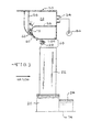
- the motor vehicle 10 includes a prime mover 12 which may be either a Diesel engine, Otto cycle engine as illustrated or other heat generating power plant.
- the prime mover 12 is secured to the frame 14 or other body structure by a plurality of resilient engine mounts 16 one of which is illustrated in Figure 1.
- the engine mounts 16 damp vibration and allow limited and controlled motion of the prime mover 12 relative to the frame or unibody 14 of the motor vehicle 10.
- the power generated by the prime mover 12 is transferred through a transmission 18 to associated driveline components (not illustrated).
- a fan 20 having a plurality of radially and obliquely oriented fan blades 22.
- the fan 20 may be disposed upon a shaft 24 of a water pump 26 or may be independently mounted, as desired.
- a radiator 28 Forward of the fan 20 is a radiator 28.
- the radiator 28 is conventional and functions as a heat exchanger, receiving a flow of engine coolant through internal, vertical or horizontal passageways 32. The engine coolant gives up heat to air which moves horizontally, that is, from left to right in Figure 1, through the radiator 28.
- a decorative grill 36 is disposed forward of the radiator 28 and provides an attractive appearance as well as a modicum of protection to the radiator. 28.
- a bumper 38 is secured to the frame or unibody 14 and also protects the forward end of the motor vehicle 10.
- a hinged hood 42 covers the prime mover 12 and other components in the engine compartment as will be readily appreciated.
- a fan shroud 50 disposed intermediate and proximate the fan 20 and radiator 28 is a fan shroud 50.
- the fan shroud 50 is secured to and moves with the radiator 28 which, in turn, is securely fastened to the frame or unibody 14.
- the fan 20 is attached to the prime mover 12 and the prime mover 12 is secured to the frame or unibody 14 through resilient engine mounts 16
- relative motion can and does occur between the fan 20 and the fan shroud 50.
- the one inch (25.4 mm) annular spacing between the tips of the blade 22 and the fan shroud 50 constitutes an area of 66 square inches (425.4 square cm).
- fan efficiencies on the order of 16% have been observed. It is believed that such efficiencies are the result of significant backflow through the annulus defined by the tips of the fan blades 22 and the most proximate surface of the fan shroud 50.
- the imposed axial flow will also limit the localized flow from the pressure-side to the suction-side of the fan blade. Thus localized flow contributes to the "tip loss" phenomenon of such fans.
- the fan shroud 50 defines a circumferentially continuous interior passageway or plenum 52.
- the circumferential plenum 52 preferably is in fluid communication with a plurality of inlet ports 54 which, in turn, communicate with one or more sources of low pressure air such as a pump 56.
- a single inlet port 54 will suffice to pressurize the plenum 52 improved air distribution and operation is achieved with multiple ports 54.
- the air is preferably provided at a pressure of between about 3 to 5 inches of water gauge or about 8 to 13.3 mbar. Depending upon the flow characteristics desired, the pressure in the engine compartment and other variables, it is anticipated that an operable range for such air pressure is from about 2 to about 10 inches of water gauge (5.32 to 26.6 mbar).
- the shroud 50 includes interior walls 58 which define the passageway or plenum 52 and converge to a throat 60.
- An overhanging lip 62 defines one portion of the throat 60 and the other portion of the throat 60 is defined by a curved circumferential Coanda surface 64.
- the Coanda surface 64 causes the air moving through the throat 60 to continue to curve along the Coanda surface 64 thereby providing an air flow having a representative velocity profile 66 and directing air flow through the annular space 68 between the Coanda surface 64 and the tips of the fan blades 22.
- a plurality of radially disposed webs 72 which span the throat 60 ensure maintenance of the desired width of the throat 60 and generally strengthen the shroud 50.
- the interior walls 56, the throat 60, the lip 62 and the Coanda surface 64 are preferably axisymmetric about a center reference axis 74. Viewing the profile of the Coanda surface 64 and the overhanging lip 62, it will be appreciated that the utilization of a Coanda surface 64 not only achieves air flow in the annular space 68 but presents a smooth aerodynamic surface to the air passing through the peripheral regions of the radiator 28 as it moves towards the fan 20, thereby also improving fan efficiency.
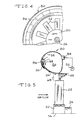
- FIG. 5 a first alternate embodiment fan shroud is illustrated and designated by the reference numeral 80.
- the first alternate embodiment fan shroud 80 defines a formed or curled body having an axisymmetric shape suggestive of a torus.
- the cross section illustrated in Figure 5 generally represents the cross section of the fan shroud 80 about its circumference, with certain exceptions.
- the exceptions relate to the plurality of air inlet ports 84 which provide fluid communication into the interior or plenum 86 of the shroud 80 at a plurality of circumferential locations about the shroud 80.
- a plurality of inlet ports 84 provide uniform airflow and thus optimum operation.
- construction and operation with, for example, a single or double inlet ports 84 is readily possible.
- the continuous sidewall 82 of the shroud 80 is formed into a reverse curved terminal portion 88 on the interior which provides an appropriately streamlined surface as the air travels toward a throat 90.
- the throat 90 is, of course, defined by the continuous curved sidewall 82 which is a Coanda surface 94 which directs airflow into the annular space 68 between the tips of the fan blades 22 and the first alternate embodiment shroud 80.
- Circumferentially spaced around the shroud 80 at a plurality of locations between the portions of the sidewall 82 which define the throat 90 are webs 96 which maintain the shape of the throat 90 and thus maintain the desired air velocity profile 98 illustrated schematically in Figure 5.
- the precise size and shape, that is, the profile of the curved Coanda surfaces 64 and 94 of the preferred and alternate embodiment shrouds 50 and 80, respectively, is not critical to obtaining a desired velocity profile. Rather, the width of the throats 60 and 90 and the pressure of the air provided to the plenums 52 and 86 of the shrouds 50 and 80, respectively provide readily adjustable parameters by which the velocity profile may be adjusted to provide optimum operation and fan efficiency in differing applications and operating conditions.
- the present invention is deemed to include the real time adjustment of air pressure delivered to the plenums 52 and 86 in response to one or more sensed variables such as underhood temperature, ambient temperature, engine compartment pressure or engine speed to change the velocity profile of the air delivered to the annular space 68 by the fan shrouds 50 and 80.
- the preferred and alternate embodiment shrouds 50 and 80 both incorporate the present invention but disclose differences based primarily on different approaches to the manufacture and assembly of the shrouds.
- the preferred embodiment shroud 50 as illustrated in Figure 3, may be fabricated of three or more molded plastic pieces which are fit together with mating edges and channels aligned and then secured by suitable adhesives.
- the alternate embodiment shroud 80 illustrated in Figure 5 is, however, preferably fabricated of a single piece of plastic molded material with edges which are curled and overlapped to form the final product. In either event, it is anticipated that the shrouds 50 and 80 may be molded of a temperature resistant plastic such as acrylonitrile-butadiene-styrene (ABS).
- ABS acrylonitrile-butadiene-styrene
- thermosetting form i.e., cured or crosslinked
- ABS in a thermoplastic form i.e., uncured or non-crosslinked, is suitable for the molding of the alternate embodiment shroud 80 which requires additional forming (curling) after the initial molding.
Landscapes
- Engineering & Computer Science (AREA)
- Mechanical Engineering (AREA)
- General Engineering & Computer Science (AREA)
- Chemical & Material Sciences (AREA)
- Combustion & Propulsion (AREA)
- Structures Of Non-Positive Displacement Pumps (AREA)
- Cooling, Air Intake And Gas Exhaust, And Fuel Tank Arrangements In Propulsion Units (AREA)
- Heating, Cooling, Or Curing Plastics Or The Like In General (AREA)
- Telephone Function (AREA)
Abstract
Description
Claims (13)
- An assembly comprising in combination an axial flow fan (20) having a plurality of blade tips, a shroud (50, 80) having a substantially circular opening for receiving said fan and including a Coanda surface (64; 94) spaced apart from said blade tips by an annular spacing (68), characterized in that
said shroud comprises an interior passage (52; 86) having sidewalls (58; 82) converging into a circular throat (60; 90) extending about said fan adjacent said Coanda surface and communicating with said interior passage (52; 82) for directing air from said interior passage toward said annular spacing (68), and
said assembly further comprising means (56) for providing air to said interior passage (52; 82) of said shroud. - The shroud assembly of claim 1 further including a plurality of webs (72) disposed across said circular throat (60; 90).
- The shroud assembly of claims 1 or 2 wherein said shroud (50; 80) is axisymmetric about the axis of rotation of such fan (20).
- The shroud assembly of any one of claims 1 to 3 wherein said shroud (50; 80) is disposed adjacent a motor vehicle radiator (28) and said fan (20) is disposed upon and driven by a prime mover (12) of such motor vehicle.
- The shroud assembly of any one of claims 1 to 4 wherein said means (56) for providing air includes an air pump (56) for providing air at a pressure of about 26.6 mbar (10 inches water gauge) or less.
- The shroud assembly of any one of claims 1 to 5 wherein said circular throat (60; 90) defines a width extending generally perpendicularly to an adjacent portion of said adjacent curved surface (64; 94).
- The shroud assembly of any one of claims 1 to 6 wherein said shroud (50; 80) includes a plurality of inlet ports (54; 84) in fluid communication with said air providing means (56) and said interior passage (52; 86).
- The shroud assembly of any one of claims 1 to 7 wherein a radial spacing between said fan (20) and said opening of said shroud (50; 80) is about 25.4 mm (1 inch).
- Use of a shroud assembly according to claim 1 in a motor vehicle cooling system further including a radiator (28) disposed adjacent said shroud (50; 80).
- A method of operating a fan disposed in a shroud assembly according to claim 1, the method comprising the step of: providing a flow of air to said interior passage and thereby to said throat (60; 90), whereby air flows from said throat to said annular spacing adjacent said Coanda surface.
- The method of claim 10 wherein said flow of air travels generally along a portion of said Coanda surface after passing through said throat (60; 90).
- The method of claims 10 or 11 wherein said air is provided at a pressure of about 26.6 mbar (10 inches water gauge) or less.
- The method of any one of claims 10 to 12 wherein said throat (60; 90) defines a width and said width and said air pressure are adjusted to achieve a desired velocity profile.
Applications Claiming Priority (3)
| Application Number | Priority Date | Filing Date | Title |
|---|---|---|---|
| US08/585,880 US5762034A (en) | 1996-01-16 | 1996-01-16 | Cooling fan shroud |
| US585880 | 1996-01-16 | ||
| PCT/US1997/000420 WO1997026450A1 (en) | 1996-01-16 | 1997-01-14 | Improved cooling fan shroud |
Publications (3)
| Publication Number | Publication Date |
|---|---|
| EP0820557A1 EP0820557A1 (en) | 1998-01-28 |
| EP0820557A4 EP0820557A4 (en) | 2001-01-03 |
| EP0820557B1 true EP0820557B1 (en) | 2004-10-27 |
Family
ID=24343351
Family Applications (1)
| Application Number | Title | Priority Date | Filing Date |
|---|---|---|---|
| EP97901982A Expired - Lifetime EP0820557B1 (en) | 1996-01-16 | 1997-01-14 | Improved cooling fan shroud |
Country Status (6)
| Country | Link |
|---|---|
| US (2) | US5762034A (en) |
| EP (1) | EP0820557B1 (en) |
| JP (1) | JPH11502586A (en) |
| AT (1) | ATE280896T1 (en) |
| DE (1) | DE69731337D1 (en) |
| WO (1) | WO1997026450A1 (en) |
Cited By (1)
| Publication number | Priority date | Publication date | Assignee | Title |
|---|---|---|---|---|
| DE102011120865B3 (en) * | 2011-12-12 | 2012-11-15 | Audi Ag | Vehicle, has fan assembly generating airflow through heat exchanger and including fan, which generates strong adjacent airflow using primary airflow from annular element, where fan assembly is designed as component of radiator grill |
Families Citing this family (133)
| Publication number | Priority date | Publication date | Assignee | Title |
|---|---|---|---|---|
| US6244817B1 (en) * | 1996-12-05 | 2001-06-12 | Mcdonnell Douglas Corporation | Method and apparatus for a fan noise controller |
| EP1094223A3 (en) * | 1999-10-20 | 2002-04-24 | Siemens Canada Limited | Integrated engine cooling fan module |
| JP3526424B2 (en) * | 1999-11-30 | 2004-05-17 | 本田技研工業株式会社 | Radiator mounting structure |
| US6474290B1 (en) | 2000-06-29 | 2002-11-05 | Kohler Co. | Engine cover |
| US6611071B2 (en) | 2001-08-17 | 2003-08-26 | Siemens Automotive Inc. | Embedded electronics for high convection cooling in an engine cooling motor application |
| EP1485624B1 (en) * | 2002-03-15 | 2007-08-29 | Robert Bosch Corporation | Engine-cooling fan assembly with overlapping fans |
| DE10355240A1 (en) * | 2003-11-26 | 2005-07-07 | Rolls-Royce Deutschland Ltd & Co Kg | Fluid flow machine with fluid removal |
| DE10355241A1 (en) * | 2003-11-26 | 2005-06-30 | Rolls-Royce Deutschland Ltd & Co Kg | Fluid flow machine with fluid supply |
| US7097414B2 (en) * | 2003-12-16 | 2006-08-29 | Pratt & Whitney Rocketdyne, Inc. | Inducer tip vortex suppressor |
| DE102004030597A1 (en) * | 2004-06-24 | 2006-01-26 | Rolls-Royce Deutschland Ltd & Co Kg | Turbomachine with external wheel jet generation at the stator |
| DE102004043036A1 (en) * | 2004-09-06 | 2006-03-09 | Rolls-Royce Deutschland Ltd & Co Kg | Fluid flow machine with fluid removal |
| DE102004055439A1 (en) * | 2004-11-17 | 2006-05-24 | Rolls-Royce Deutschland Ltd & Co Kg | Fluid flow machine with dynamic flow control |
| US7478993B2 (en) * | 2006-03-27 | 2009-01-20 | Valeo, Inc. | Cooling fan using Coanda effect to reduce recirculation |
| DE102006049076B4 (en) * | 2006-10-13 | 2019-09-26 | Mahle International Gmbh | Axial fan arranged to promote cooling air for a cooling device of a motor vehicle |
| US8475111B2 (en) * | 2007-04-05 | 2013-07-02 | Borgwarner Inc. | Ring fan and shroud air guide system |
| US20080315042A1 (en) * | 2007-06-20 | 2008-12-25 | General Electric Company | Thrust generator for a propulsion system |
| DE102007037924A1 (en) * | 2007-08-10 | 2009-02-12 | Rolls-Royce Deutschland Ltd & Co Kg | Turbomachine with Ringkanalwandausnehmung |
| GB2452593A (en) * | 2007-09-04 | 2009-03-11 | Dyson Technology Ltd | A fan |
| GB2452490A (en) * | 2007-09-04 | 2009-03-11 | Dyson Technology Ltd | Bladeless fan |
| CN101468365B (en) * | 2007-12-29 | 2011-03-30 | 富准精密工业(深圳)有限公司 | Air guide device and workpiece cooling device adopting the air guide device |
| DE102008011644A1 (en) * | 2008-02-28 | 2009-09-03 | Rolls-Royce Deutschland Ltd & Co Kg | Housing structuring for axial compressor in the hub area |
| AU325226S (en) | 2008-06-06 | 2009-03-24 | Dyson Technology Ltd | Fan head |
| AU325225S (en) | 2008-06-06 | 2009-03-24 | Dyson Technology Ltd | A fan |
| DE102008031982A1 (en) * | 2008-07-07 | 2010-01-14 | Rolls-Royce Deutschland Ltd & Co Kg | Turbomachine with groove at a trough of a blade end |
| DE102008037154A1 (en) | 2008-08-08 | 2010-02-11 | Rolls-Royce Deutschland Ltd & Co Kg | Turbomachine |
| GB2463698B (en) * | 2008-09-23 | 2010-12-01 | Dyson Technology Ltd | A fan |
| DE102008052409A1 (en) | 2008-10-21 | 2010-04-22 | Rolls-Royce Deutschland Ltd & Co Kg | Turbomachine with near-suction edge energization |
| GB2464736A (en) * | 2008-10-25 | 2010-04-28 | Dyson Technology Ltd | Fan with a filter |
| CA130551S (en) | 2008-11-07 | 2009-12-31 | Dyson Ltd | Fan |
| GB2466058B (en) | 2008-12-11 | 2010-12-22 | Dyson Technology Ltd | Fan nozzle with spacers |
| GB2468315A (en) * | 2009-03-04 | 2010-09-08 | Dyson Technology Ltd | Tilting fan |
| GB2468323A (en) * | 2009-03-04 | 2010-09-08 | Dyson Technology Ltd | Fan assembly |
| GB0903682D0 (en) * | 2009-03-04 | 2009-04-15 | Dyson Technology Ltd | A fan |
| GB2468312A (en) | 2009-03-04 | 2010-09-08 | Dyson Technology Ltd | Fan assembly |
| GB2468325A (en) * | 2009-03-04 | 2010-09-08 | Dyson Technology Ltd | Height adjustable fan with nozzle |
| GB2476171B (en) * | 2009-03-04 | 2011-09-07 | Dyson Technology Ltd | Tilting fan stand |
| KR101370271B1 (en) * | 2009-03-04 | 2014-03-04 | 다이슨 테크놀러지 리미티드 | fan |
| GB2468326A (en) * | 2009-03-04 | 2010-09-08 | Dyson Technology Ltd | Telescopic pedestal fan |
| GB2468331B (en) | 2009-03-04 | 2011-02-16 | Dyson Technology Ltd | A fan |
| AU2010219495B2 (en) | 2009-03-04 | 2011-11-10 | Dyson Technology Limited | A fan |
| GB2468320C (en) | 2009-03-04 | 2011-06-01 | Dyson Technology Ltd | Tilting fan |
| GB2468317A (en) * | 2009-03-04 | 2010-09-08 | Dyson Technology Ltd | Height adjustable and oscillating fan |
| EP2414738B1 (en) | 2009-03-04 | 2013-10-09 | Dyson Technology Limited | Humidifying apparatus |
| GB2468329A (en) * | 2009-03-04 | 2010-09-08 | Dyson Technology Ltd | Fan assembly |
| CA2746496C (en) * | 2009-03-04 | 2012-12-04 | Dyson Technology Limited | A fan assembly |
| GB0919473D0 (en) * | 2009-11-06 | 2009-12-23 | Dyson Technology Ltd | A fan |
| US20110116934A1 (en) * | 2009-11-16 | 2011-05-19 | Meng Sen Y | Pumping element design |
| GB2478927B (en) | 2010-03-23 | 2016-09-14 | Dyson Technology Ltd | Portable fan with filter unit |
| GB2478925A (en) * | 2010-03-23 | 2011-09-28 | Dyson Technology Ltd | External filter for a fan |
| CN201696365U (en) * | 2010-05-20 | 2011-01-05 | 张钜标 | A flat jet fan |
| ES2553148T3 (en) * | 2010-05-27 | 2015-12-04 | Dyson Technology Limited | Air blowing device by means of a narrow slit nozzle assembly |
| CN101865149B (en) * | 2010-07-12 | 2011-04-06 | 魏建峰 | Multifunctional super-silent fan |
| GB2482548A (en) | 2010-08-06 | 2012-02-08 | Dyson Technology Ltd | A fan assembly with a heater |
| GB2482547A (en) | 2010-08-06 | 2012-02-08 | Dyson Technology Ltd | A fan assembly with a heater |
| GB2482549A (en) * | 2010-08-06 | 2012-02-08 | Dyson Technology Ltd | A fan assembly with a heater |
| GB2483448B (en) | 2010-09-07 | 2015-12-02 | Dyson Technology Ltd | A fan |
| USD672024S1 (en) | 2010-09-11 | 2012-12-04 | Dyson Limited | Fan |
| US10100836B2 (en) | 2010-10-13 | 2018-10-16 | Dyson Technology Limited | Fan assembly |
| WO2012052735A1 (en) | 2010-10-18 | 2012-04-26 | Dyson Technology Limited | A fan assembly |
| GB2484670B (en) | 2010-10-18 | 2018-04-25 | Dyson Technology Ltd | A fan assembly |
| JP5778293B2 (en) | 2010-11-02 | 2015-09-16 | ダイソン テクノロジー リミテッド | Blower assembly |
| US9567942B1 (en) * | 2010-12-02 | 2017-02-14 | Concepts Nrec, Llc | Centrifugal turbomachines having extended performance ranges |
| GB2486019B (en) | 2010-12-02 | 2013-02-20 | Dyson Technology Ltd | A fan |
| GB2486890B (en) | 2010-12-23 | 2017-09-06 | Dyson Technology Ltd | A fan |
| GB2486892B (en) | 2010-12-23 | 2017-11-15 | Dyson Technology Ltd | A fan |
| GB2486889B (en) | 2010-12-23 | 2017-09-06 | Dyson Technology Ltd | A fan |
| US10041505B2 (en) | 2011-06-14 | 2018-08-07 | Robert Bosch Llc | Airflow assembly having improved acoustical performance |
| TWM416690U (en) * | 2011-06-16 | 2011-11-21 | Kable Entpr Co Ltd | Blade-free fan with flow guide structure |
| GB2492961A (en) | 2011-07-15 | 2013-01-23 | Dyson Technology Ltd | Fan with impeller and motor inside annular casing |
| GB2492962A (en) | 2011-07-15 | 2013-01-23 | Dyson Technology Ltd | Fan with tangential inlet to casing passage |
| GB2492963A (en) | 2011-07-15 | 2013-01-23 | Dyson Technology Ltd | Fan with scroll casing decreasing in cross-section |
| GB2493506B (en) * | 2011-07-27 | 2013-09-11 | Dyson Technology Ltd | A fan assembly |
| AU2012288597B2 (en) * | 2011-07-27 | 2015-04-09 | Dyson Technology Limited | A fan assembly |
| KR101203379B1 (en) | 2011-07-27 | 2012-11-21 | 이광식 | Ring nozzle of no bladeless fan |
| DE112011105574B4 (en) * | 2011-08-30 | 2025-04-30 | Luoyang Northglass Technology Co., Ltd. | Air amplifier having a function for amplifying an air flow |
| JP5408227B2 (en) * | 2011-10-31 | 2014-02-05 | ダイキン工業株式会社 | Air conditioning indoor unit |
| GB201119500D0 (en) | 2011-11-11 | 2011-12-21 | Dyson Technology Ltd | A fan assembly |
| GB2496877B (en) | 2011-11-24 | 2014-05-07 | Dyson Technology Ltd | A fan assembly |
| DE102011087831A1 (en) * | 2011-12-06 | 2013-06-06 | Robert Bosch Gmbh | blower assembly |
| JP5338895B2 (en) * | 2011-12-28 | 2013-11-13 | ダイキン工業株式会社 | Air conditioning indoor unit |
| GB2498547B (en) | 2012-01-19 | 2015-02-18 | Dyson Technology Ltd | A fan |
| GB2499042A (en) | 2012-02-06 | 2013-08-07 | Dyson Technology Ltd | A nozzle for a fan assembly |
| GB2499041A (en) | 2012-02-06 | 2013-08-07 | Dyson Technology Ltd | Bladeless fan including an ionizer |
| GB2499044B (en) | 2012-02-06 | 2014-03-19 | Dyson Technology Ltd | A fan |
| GB2500010B (en) | 2012-03-06 | 2016-08-24 | Dyson Technology Ltd | A humidifying apparatus |
| GB2500005B (en) | 2012-03-06 | 2014-08-27 | Dyson Technology Ltd | A method of generating a humid air flow |
| GB2500011B (en) | 2012-03-06 | 2016-07-06 | Dyson Technology Ltd | A Humidifying Apparatus |
| GB2500017B (en) | 2012-03-06 | 2015-07-29 | Dyson Technology Ltd | A Humidifying Apparatus |
| GB2500012B (en) | 2012-03-06 | 2016-07-06 | Dyson Technology Ltd | A Humidifying Apparatus |
| KR101699293B1 (en) | 2012-03-06 | 2017-01-24 | 다이슨 테크놀러지 리미티드 | A fan assembly |
| GB2500903B (en) | 2012-04-04 | 2015-06-24 | Dyson Technology Ltd | Heating apparatus |
| GB2501301B (en) | 2012-04-19 | 2016-02-03 | Dyson Technology Ltd | A fan assembly |
| GB2502103B (en) | 2012-05-16 | 2015-09-23 | Dyson Technology Ltd | A fan |
| GB2532557B (en) | 2012-05-16 | 2017-01-11 | Dyson Technology Ltd | A fan comprsing means for suppressing noise |
| EP2850324A2 (en) | 2012-05-16 | 2015-03-25 | Dyson Technology Limited | A fan |
| US9885368B2 (en) | 2012-05-24 | 2018-02-06 | Carrier Corporation | Stall margin enhancement of axial fan with rotating shroud |
| GB2503907B (en) | 2012-07-11 | 2014-05-28 | Dyson Technology Ltd | A fan assembly |
| CN102889239A (en) * | 2012-11-02 | 2013-01-23 | 李起武 | Fan |
| CN104781519B (en) * | 2012-11-28 | 2017-06-23 | 博格华纳公司 | The compressor stage of the vortex supercharger with flow amplifier |
| BR302013003358S1 (en) | 2013-01-18 | 2014-11-25 | Dyson Technology Ltd | CONFIGURATION APPLIED ON HUMIDIFIER |
| AU350181S (en) | 2013-01-18 | 2013-08-15 | Dyson Technology Ltd | Humidifier or fan |
| AU350140S (en) | 2013-01-18 | 2013-08-13 | Dyson Technology Ltd | Humidifier or fan |
| AU350179S (en) | 2013-01-18 | 2013-08-15 | Dyson Technology Ltd | Humidifier or fan |
| GB2510195B (en) | 2013-01-29 | 2016-04-27 | Dyson Technology Ltd | A fan assembly |
| CA2899747A1 (en) | 2013-01-29 | 2014-08-07 | Dyson Technology Limited | A fan assembly |
| CA152657S (en) | 2013-03-07 | 2014-05-20 | Dyson Technology Ltd | Fan |
| CA152658S (en) | 2013-03-07 | 2014-05-20 | Dyson Technology Ltd | Fan |
| BR302013004394S1 (en) | 2013-03-07 | 2014-12-02 | Dyson Technology Ltd | CONFIGURATION APPLIED TO FAN |
| CA152655S (en) | 2013-03-07 | 2014-05-20 | Dyson Technology Ltd | Fan |
| USD729372S1 (en) | 2013-03-07 | 2015-05-12 | Dyson Technology Limited | Fan |
| CA152656S (en) | 2013-03-07 | 2014-05-20 | Dyson Technology Ltd | Fan |
| GB2511757B (en) * | 2013-03-11 | 2016-06-15 | Dyson Technology Ltd | Fan assembly nozzle with control port |
| GB2530906B (en) | 2013-07-09 | 2017-05-10 | Dyson Technology Ltd | A fan assembly |
| CA154722S (en) | 2013-08-01 | 2015-02-16 | Dyson Technology Ltd | Fan |
| CA154723S (en) | 2013-08-01 | 2015-02-16 | Dyson Technology Ltd | Fan |
| TWD172707S (en) | 2013-08-01 | 2015-12-21 | 戴森科技有限公司 | A fan |
| GB2518638B (en) | 2013-09-26 | 2016-10-12 | Dyson Technology Ltd | Humidifying apparatus |
| JP1518059S (en) | 2014-01-09 | 2015-02-23 | ||
| JP1518058S (en) | 2014-01-09 | 2015-02-23 | ||
| US10569827B2 (en) | 2014-04-17 | 2020-02-25 | Thomas S. Felker | Bicycle dual power turning track, rack, pinion, and one-way bearing propulsion system |
| US9580137B2 (en) | 2014-04-17 | 2017-02-28 | Thomas S. Felker | Dual powered propulsion system |
| GB2528704A (en) | 2014-07-29 | 2016-02-03 | Dyson Technology Ltd | Humidifying apparatus |
| GB2528709B (en) | 2014-07-29 | 2017-02-08 | Dyson Technology Ltd | Humidifying apparatus |
| GB2528708B (en) | 2014-07-29 | 2016-06-29 | Dyson Technology Ltd | A fan assembly |
| ES2978931T3 (en) * | 2015-03-04 | 2024-09-23 | Airmaster As | System for distributing air in a room |
| FR3034145B1 (en) * | 2015-03-26 | 2017-04-07 | Snecma | COMPRESSOR FLOOR |
| JP6627391B2 (en) * | 2015-10-07 | 2020-01-08 | いすゞ自動車株式会社 | Cooling module |
| US10569129B2 (en) | 2016-04-15 | 2020-02-25 | Thomas S. Felker | Tri-power exercising device |
| US12268931B2 (en) | 2016-04-15 | 2025-04-08 | Thomas S. Felker | Exercise system |
| BR112018073722A2 (en) * | 2016-05-18 | 2019-02-26 | De' Longhi Appliances S.R.L. Con Unico Socio | fan |
| US20180066677A1 (en) * | 2016-08-15 | 2018-03-08 | Chia-Ning Yang | Fan |
| GB2575064B (en) * | 2018-06-27 | 2021-06-09 | Dyson Technology Ltd | A nozzle for a fan assembly |
| CN112253500A (en) * | 2020-09-09 | 2021-01-22 | 武汉格罗夫氢能汽车有限公司 | High-low pressure air flow mixed electronic fan for hydrogen energy automobile |
Family Cites Families (20)
| Publication number | Priority date | Publication date | Assignee | Title |
|---|---|---|---|---|
| US2785620A (en) * | 1954-02-24 | 1957-03-19 | Harlan C Welch | Wind director |
| US3799128A (en) * | 1973-03-08 | 1974-03-26 | Gen Motors Corp | Engine cooling system radiator and fan shroud |
| US3937189A (en) * | 1974-01-28 | 1976-02-10 | International Harvester Company | Fan shroud exit structure |
| US3937192A (en) * | 1974-09-03 | 1976-02-10 | General Motors Corporation | Ejector fan shroud arrangement |
| US4136735A (en) * | 1975-01-24 | 1979-01-30 | International Harvester Company | Heat exchange apparatus including a toroidal-type radiator |
| FR2347533A2 (en) * | 1975-10-30 | 1977-11-04 | Saviem | ENGINE COOLING SYSTEM |
| DE2657840B2 (en) * | 1976-12-21 | 1979-07-26 | Sueddeutsche Kuehlerfabrik Julius Fr. Behr Gmbh & Co Kg, 7000 Stuttgart | Cooling system for internal combustion engines |
| US4181172A (en) * | 1977-07-01 | 1980-01-01 | General Motors Corporation | Fan shroud arrangement |
| US4329946A (en) * | 1979-10-09 | 1982-05-18 | General Motors Corporation | Shroud arrangement for engine cooling fan |
| US4406581A (en) * | 1980-12-30 | 1983-09-27 | Hayes-Albion Corp. | Shrouded fan assembly |
| US4398508A (en) * | 1981-02-20 | 1983-08-16 | Volvo White Truck Corporation | Engine cooling fan construction |
| US4685513A (en) * | 1981-11-24 | 1987-08-11 | General Motors Corporation | Engine cooling fan and fan shrouding arrangement |
| IT8353039U1 (en) * | 1982-03-15 | 1984-09-10 | Sueddeutsche Kuehlerfabrik Julius Fr Behr Gmbh & Co Kg | Axial fan, especially for cooling radiators of water-cooled internal combustion engines |
| US4548548A (en) * | 1984-05-23 | 1985-10-22 | Airflow Research And Manufacturing Corp. | Fan and housing |
| JPS62195494A (en) * | 1986-02-21 | 1987-08-28 | Aisin Seiki Co Ltd | Cooling device for internal combustion engine |
| US4927328A (en) * | 1989-03-02 | 1990-05-22 | Scoates William D | Shroud assembly for axial flow fans |
| DE69126136T2 (en) * | 1990-07-09 | 1997-12-11 | Deco-Grand, Inc., Royal Oak, Mich. | WATER PUMP |
| US5216983A (en) * | 1992-10-26 | 1993-06-08 | Harvard Industries, Inc. | Vehicle hydraulic cooling fan system |
| DE4438184C1 (en) * | 1994-10-26 | 1996-04-11 | Behr Gmbh & Co | Axial air fan for heavy goods vehicle radiator |
| US5590624A (en) * | 1995-03-31 | 1997-01-07 | Caterpillar Inc. | Engine cooling systems |
-
1996
- 1996-01-16 US US08/585,880 patent/US5762034A/en not_active Expired - Fee Related
-
1997
- 1997-01-14 JP JP9526080A patent/JPH11502586A/en active Pending
- 1997-01-14 AT AT97901982T patent/ATE280896T1/en not_active IP Right Cessation
- 1997-01-14 EP EP97901982A patent/EP0820557B1/en not_active Expired - Lifetime
- 1997-01-14 WO PCT/US1997/000420 patent/WO1997026450A1/en not_active Ceased
- 1997-01-14 DE DE69731337T patent/DE69731337D1/en not_active Expired - Lifetime
- 1997-09-04 US US08/923,886 patent/US5881685A/en not_active Expired - Fee Related
Cited By (1)
| Publication number | Priority date | Publication date | Assignee | Title |
|---|---|---|---|---|
| DE102011120865B3 (en) * | 2011-12-12 | 2012-11-15 | Audi Ag | Vehicle, has fan assembly generating airflow through heat exchanger and including fan, which generates strong adjacent airflow using primary airflow from annular element, where fan assembly is designed as component of radiator grill |
Also Published As
| Publication number | Publication date |
|---|---|
| ATE280896T1 (en) | 2004-11-15 |
| WO1997026450A1 (en) | 1997-07-24 |
| US5762034A (en) | 1998-06-09 |
| JPH11502586A (en) | 1999-03-02 |
| EP0820557A1 (en) | 1998-01-28 |
| EP0820557A4 (en) | 2001-01-03 |
| DE69731337D1 (en) | 2004-12-02 |
| US5881685A (en) | 1999-03-16 |
Similar Documents
| Publication | Publication Date | Title |
|---|---|---|
| EP0820557B1 (en) | Improved cooling fan shroud | |
| US7108482B2 (en) | Centrifugal blower | |
| US4180130A (en) | Heat exchange apparatus including a toroidal-type radiator | |
| US4136735A (en) | Heat exchange apparatus including a toroidal-type radiator | |
| EP0649978B1 (en) | Airflow ejector for an automotive vehicle | |
| US4184541A (en) | Heat exchange apparatus including a toroidal-type radiator | |
| US4173995A (en) | Recirculation barrier for a heat transfer system | |
| US5765630A (en) | Radiator with air flow directing fins | |
| US5423660A (en) | Fan inlet with curved lip and cylindrical member forming labyrinth seal | |
| US3872916A (en) | Fan shroud exit structure | |
| EP0887558B1 (en) | Axial flow fan | |
| US4396351A (en) | Engine cooling fan | |
| EP1141528B1 (en) | Cooling system for an off-highway vehicle | |
| US5758716A (en) | Radiator unit for internal combustion engine | |
| EP0799979A1 (en) | Engine cooler and construction machines | |
| JP2000501808A (en) | High efficiency, low noise axial fan assembly | |
| US5626185A (en) | Airflow ejector system for an automotive vehicle with wheel-well ejectors | |
| WO1999031391A1 (en) | Radiator cooling fan | |
| US4211514A (en) | Mixed flow fan | |
| US5971709A (en) | Radiator fan for internal combustion engines | |
| EP1048832B1 (en) | "Supercharged internal-combustion engine" | |
| EP0779419B1 (en) | Improvements made in the engine assembly of automotive vehicles | |
| US12338888B2 (en) | Space-saving gearbox cooler device and gearbox | |
| CN117052520A (en) | Ventilator module for heat exchangers used in drives of motor vehicles | |
| CA1044972A (en) | Combination fan shroud and toroidal radiator |
Legal Events
| Date | Code | Title | Description |
|---|---|---|---|
| PUAI | Public reference made under article 153(3) epc to a published international application that has entered the european phase |
Free format text: ORIGINAL CODE: 0009012 |
|
| 17P | Request for examination filed |
Effective date: 19971014 |
|
| AK | Designated contracting states |
Kind code of ref document: A1 Designated state(s): AT BE CH DE DK ES FI FR GB GR IE IT LI LU MC NL PT SE |
|
| A4 | Supplementary search report drawn up and despatched |
Effective date: 20001121 |
|
| AK | Designated contracting states |
Kind code of ref document: A4 Designated state(s): AT BE CH DE DK ES FI FR GB GR IE IT LI LU MC NL PT SE |
|
| 17Q | First examination report despatched |
Effective date: 20020923 |
|
| GRAP | Despatch of communication of intention to grant a patent |
Free format text: ORIGINAL CODE: EPIDOSNIGR1 |
|
| GRAS | Grant fee paid |
Free format text: ORIGINAL CODE: EPIDOSNIGR3 |
|
| GRAA | (expected) grant |
Free format text: ORIGINAL CODE: 0009210 |
|
| AK | Designated contracting states |
Kind code of ref document: B1 Designated state(s): AT BE CH DE DK ES FI FR GB GR IE IT LI LU MC NL PT SE |
|
| PG25 | Lapsed in a contracting state [announced via postgrant information from national office to epo] |
Ref country code: NL Free format text: LAPSE BECAUSE OF FAILURE TO SUBMIT A TRANSLATION OF THE DESCRIPTION OR TO PAY THE FEE WITHIN THE PRESCRIBED TIME-LIMIT Effective date: 20041027 Ref country code: LI Free format text: LAPSE BECAUSE OF FAILURE TO SUBMIT A TRANSLATION OF THE DESCRIPTION OR TO PAY THE FEE WITHIN THE PRESCRIBED TIME-LIMIT Effective date: 20041027 Ref country code: IT Free format text: LAPSE BECAUSE OF FAILURE TO SUBMIT A TRANSLATION OF THE DESCRIPTION OR TO PAY THE FEE WITHIN THE PRE;WARNING: LAPSES OF ITALIAN PATENTS WITH EFFECTIVE DATE BEFORE 2007 MAY HAVE OCCURRED AT ANY TIME BEFORE 2007. THE CORRECT EFFECTIVE DATE MAY BE DIFFERENT FROM THE ONE RECORDED.SCRIBED TIME-LIMIT Effective date: 20041027 Ref country code: FR Free format text: LAPSE BECAUSE OF FAILURE TO SUBMIT A TRANSLATION OF THE DESCRIPTION OR TO PAY THE FEE WITHIN THE PRESCRIBED TIME-LIMIT Effective date: 20041027 Ref country code: FI Free format text: LAPSE BECAUSE OF FAILURE TO SUBMIT A TRANSLATION OF THE DESCRIPTION OR TO PAY THE FEE WITHIN THE PRESCRIBED TIME-LIMIT Effective date: 20041027 Ref country code: CH Free format text: LAPSE BECAUSE OF FAILURE TO SUBMIT A TRANSLATION OF THE DESCRIPTION OR TO PAY THE FEE WITHIN THE PRESCRIBED TIME-LIMIT Effective date: 20041027 Ref country code: BE Free format text: LAPSE BECAUSE OF FAILURE TO SUBMIT A TRANSLATION OF THE DESCRIPTION OR TO PAY THE FEE WITHIN THE PRESCRIBED TIME-LIMIT Effective date: 20041027 Ref country code: AT Free format text: LAPSE BECAUSE OF FAILURE TO SUBMIT A TRANSLATION OF THE DESCRIPTION OR TO PAY THE FEE WITHIN THE PRESCRIBED TIME-LIMIT Effective date: 20041027 |
|
| REG | Reference to a national code |
Ref country code: GB Ref legal event code: FG4D |
|
| REG | Reference to a national code |
Ref country code: CH Ref legal event code: EP |
|
| REG | Reference to a national code |
Ref country code: IE Ref legal event code: FG4D |
|
| REF | Corresponds to: |
Ref document number: 69731337 Country of ref document: DE Date of ref document: 20041202 Kind code of ref document: P |
|
| PG25 | Lapsed in a contracting state [announced via postgrant information from national office to epo] |
Ref country code: LU Free format text: LAPSE BECAUSE OF NON-PAYMENT OF DUE FEES Effective date: 20050114 Ref country code: IE Free format text: LAPSE BECAUSE OF NON-PAYMENT OF DUE FEES Effective date: 20050114 |
|
| PG25 | Lapsed in a contracting state [announced via postgrant information from national office to epo] |
Ref country code: SE Free format text: LAPSE BECAUSE OF FAILURE TO SUBMIT A TRANSLATION OF THE DESCRIPTION OR TO PAY THE FEE WITHIN THE PRESCRIBED TIME-LIMIT Effective date: 20050127 Ref country code: GR Free format text: LAPSE BECAUSE OF FAILURE TO SUBMIT A TRANSLATION OF THE DESCRIPTION OR TO PAY THE FEE WITHIN THE PRESCRIBED TIME-LIMIT Effective date: 20050127 Ref country code: GB Free format text: LAPSE BECAUSE OF NON-PAYMENT OF DUE FEES Effective date: 20050127 Ref country code: DK Free format text: LAPSE BECAUSE OF FAILURE TO SUBMIT A TRANSLATION OF THE DESCRIPTION OR TO PAY THE FEE WITHIN THE PRESCRIBED TIME-LIMIT Effective date: 20050127 |
|
| PG25 | Lapsed in a contracting state [announced via postgrant information from national office to epo] |
Ref country code: DE Free format text: LAPSE BECAUSE OF FAILURE TO SUBMIT A TRANSLATION OF THE DESCRIPTION OR TO PAY THE FEE WITHIN THE PRESCRIBED TIME-LIMIT Effective date: 20050128 |
|
| PG25 | Lapsed in a contracting state [announced via postgrant information from national office to epo] |
Ref country code: MC Free format text: LAPSE BECAUSE OF NON-PAYMENT OF DUE FEES Effective date: 20050131 |
|
| PG25 | Lapsed in a contracting state [announced via postgrant information from national office to epo] |
Ref country code: ES Free format text: LAPSE BECAUSE OF FAILURE TO SUBMIT A TRANSLATION OF THE DESCRIPTION OR TO PAY THE FEE WITHIN THE PRESCRIBED TIME-LIMIT Effective date: 20050207 |
|
| REG | Reference to a national code |
Ref country code: CH Ref legal event code: PL |
|
| NLV1 | Nl: lapsed or annulled due to failure to fulfill the requirements of art. 29p and 29m of the patents act | ||
| PLBE | No opposition filed within time limit |
Free format text: ORIGINAL CODE: 0009261 |
|
| STAA | Information on the status of an ep patent application or granted ep patent |
Free format text: STATUS: NO OPPOSITION FILED WITHIN TIME LIMIT |
|
| GBPC | Gb: european patent ceased through non-payment of renewal fee |
Effective date: 20050127 |
|
| 26N | No opposition filed |
Effective date: 20050728 |
|
| REG | Reference to a national code |
Ref country code: IE Ref legal event code: MM4A |
|
| EN | Fr: translation not filed | ||
| PG25 | Lapsed in a contracting state [announced via postgrant information from national office to epo] |
Ref country code: PT Free format text: LAPSE BECAUSE OF NON-PAYMENT OF DUE FEES Effective date: 20050327 |