EP0821176B1 - Elektromagnetische Kupplungsvorrichtung - Google Patents
Elektromagnetische Kupplungsvorrichtung Download PDFInfo
- Publication number
- EP0821176B1 EP0821176B1 EP97305509A EP97305509A EP0821176B1 EP 0821176 B1 EP0821176 B1 EP 0821176B1 EP 97305509 A EP97305509 A EP 97305509A EP 97305509 A EP97305509 A EP 97305509A EP 0821176 B1 EP0821176 B1 EP 0821176B1
- Authority
- EP
- European Patent Office
- Prior art keywords
- coil
- excitation coil
- electric component
- terminal
- accommodation section
- Prior art date
- Legal status (The legal status is an assumption and is not a legal conclusion. Google has not performed a legal analysis and makes no representation as to the accuracy of the status listed.)
- Expired - Lifetime
Links
- 230000008878 coupling Effects 0.000 title claims description 32
- 238000010168 coupling process Methods 0.000 title claims description 32
- 238000005859 coupling reaction Methods 0.000 title claims description 32
- 230000005284 excitation Effects 0.000 claims description 120
- 230000004308 accommodation Effects 0.000 claims description 66
- 238000004804 winding Methods 0.000 claims description 37
- WABPQHHGFIMREM-UHFFFAOYSA-N lead(0) Chemical compound [Pb] WABPQHHGFIMREM-UHFFFAOYSA-N 0.000 claims description 15
- 239000002184 metal Substances 0.000 description 16
- 229910052751 metal Inorganic materials 0.000 description 16
- 230000002093 peripheral effect Effects 0.000 description 5
- 150000002739 metals Chemical class 0.000 description 4
- 229920003002 synthetic resin Polymers 0.000 description 4
- 239000000057 synthetic resin Substances 0.000 description 4
- 230000020169 heat generation Effects 0.000 description 3
- 238000005476 soldering Methods 0.000 description 3
- 229910001369 Brass Inorganic materials 0.000 description 2
- RYGMFSIKBFXOCR-UHFFFAOYSA-N Copper Chemical compound [Cu] RYGMFSIKBFXOCR-UHFFFAOYSA-N 0.000 description 2
- XUIMIQQOPSSXEZ-UHFFFAOYSA-N Silicon Chemical compound [Si] XUIMIQQOPSSXEZ-UHFFFAOYSA-N 0.000 description 2
- 238000005452 bending Methods 0.000 description 2
- 239000010951 brass Substances 0.000 description 2
- 238000010276 construction Methods 0.000 description 2
- 229910052802 copper Inorganic materials 0.000 description 2
- 239000010949 copper Substances 0.000 description 2
- 210000003298 dental enamel Anatomy 0.000 description 2
- 238000000465 moulding Methods 0.000 description 2
- 238000005057 refrigeration Methods 0.000 description 2
- 229920005989 resin Polymers 0.000 description 2
- 239000011347 resin Substances 0.000 description 2
- 229910052710 silicon Inorganic materials 0.000 description 2
- 239000010703 silicon Substances 0.000 description 2
- 125000006850 spacer group Chemical group 0.000 description 2
- 229910000831 Steel Inorganic materials 0.000 description 1
- 238000010521 absorption reaction Methods 0.000 description 1
- 230000009471 action Effects 0.000 description 1
- 230000005540 biological transmission Effects 0.000 description 1
- 239000011248 coating agent Substances 0.000 description 1
- 238000000576 coating method Methods 0.000 description 1
- 238000005520 cutting process Methods 0.000 description 1
- 230000000694 effects Effects 0.000 description 1
- 230000004907 flux Effects 0.000 description 1
- 238000009413 insulation Methods 0.000 description 1
- 238000004519 manufacturing process Methods 0.000 description 1
- 238000005192 partition Methods 0.000 description 1
- 230000001681 protective effect Effects 0.000 description 1
- 238000004080 punching Methods 0.000 description 1
- 239000010959 steel Substances 0.000 description 1
- 238000003466 welding Methods 0.000 description 1
Images


Classifications
-
- H—ELECTRICITY
- H01—ELECTRIC ELEMENTS
- H01F—MAGNETS; INDUCTANCES; TRANSFORMERS; SELECTION OF MATERIALS FOR THEIR MAGNETIC PROPERTIES
- H01F7/00—Magnets
- H01F7/06—Electromagnets; Actuators including electromagnets
-
- F—MECHANICAL ENGINEERING; LIGHTING; HEATING; WEAPONS; BLASTING
- F16—ENGINEERING ELEMENTS AND UNITS; GENERAL MEASURES FOR PRODUCING AND MAINTAINING EFFECTIVE FUNCTIONING OF MACHINES OR INSTALLATIONS; THERMAL INSULATION IN GENERAL
- F16D—COUPLINGS FOR TRANSMITTING ROTATION; CLUTCHES; BRAKES
- F16D27/00—Magnetically- or electrically- actuated clutches; Control or electric circuits therefor
- F16D27/10—Magnetically- or electrically- actuated clutches; Control or electric circuits therefor with an electromagnet not rotating with a clutching member, i.e. without collecting rings
- F16D27/108—Magnetically- or electrically- actuated clutches; Control or electric circuits therefor with an electromagnet not rotating with a clutching member, i.e. without collecting rings with axially movable clutching members
- F16D27/112—Magnetically- or electrically- actuated clutches; Control or electric circuits therefor with an electromagnet not rotating with a clutching member, i.e. without collecting rings with axially movable clutching members with flat friction surfaces, e.g. discs
-
- F—MECHANICAL ENGINEERING; LIGHTING; HEATING; WEAPONS; BLASTING
- F16—ENGINEERING ELEMENTS AND UNITS; GENERAL MEASURES FOR PRODUCING AND MAINTAINING EFFECTIVE FUNCTIONING OF MACHINES OR INSTALLATIONS; THERMAL INSULATION IN GENERAL
- F16D—COUPLINGS FOR TRANSMITTING ROTATION; CLUTCHES; BRAKES
- F16D27/00—Magnetically- or electrically- actuated clutches; Control or electric circuits therefor
- F16D27/14—Details
-
- F—MECHANICAL ENGINEERING; LIGHTING; HEATING; WEAPONS; BLASTING
- F16—ENGINEERING ELEMENTS AND UNITS; GENERAL MEASURES FOR PRODUCING AND MAINTAINING EFFECTIVE FUNCTIONING OF MACHINES OR INSTALLATIONS; THERMAL INSULATION IN GENERAL
- F16D—COUPLINGS FOR TRANSMITTING ROTATION; CLUTCHES; BRAKES
- F16D27/00—Magnetically- or electrically- actuated clutches; Control or electric circuits therefor
- F16D2027/001—Means for electric connection of the coils of the electromagnetic clutches
Definitions
- This invention relates to an electromagnetic coupling device which is used as a solenoid clutch for transmitting a turning torque or a solenoid brake for braking the turning torque. More particularly, the present invention relates to an electromagnetic coupling device having a built-in electric component for preventing damage of an electric circuit due to a surge voltage, breakage of a V belt when a rotary member on the output side is locked, and the like.
- Friction type electromagnetic coupling devices in general, such as solenoid clutches, transmit or cut off the turning torque by passing the magnetic flux generated by the excitation of an excitation coil between a rotor and an armature disposed in such a manner that their friction surfaces are opposed to each other, and bringing the friction surfaces into and out of pressure contact with and from each other by the magnetic attraction and the repulsion of a flexible member against the magnetic attraction.
- a solenoid clutch fitted to a refrigeration compressor of an automobile for example, has a different lead length depending on the kind or model of automobile. Therefore, one kind of yoke having a built-in excitation coil cannot be used as a common automobile component for a variety of automobiles, and this is disadvantageous from the aspects of design and stock management. Therefore, various electromagnetic coupling devices where the excitation coil is connected to the lead wire on the power source side outside the yoke by changing the design of the prior art structure, wherein the excitation coil and the lead wire on the power side are connected outside the yoke, have been proposed in the past (for example, Japanese Patent Laid-Open Nos. 12108/1988 and 125322/1992 (corresponding to U.S. Patent No. 5,138,293).
- the electromagnetic coupling device described in Japanese Patent Laid-Open No. 125322/1992 (hereinafter referred to as the "prior art invention 1") was proposed by the same applicant of the present invention.
- a terminal accommodation section is formed integrally with a coil bobbin for accommodating an excitation coil
- a winding start portion and a winding end portion of the excitation coil are led into this terminal accommodation section, and a diode is connected in parallel with the excitation coil.
- the winding start portion and the winding end portion of the excitation coil are forced into the slits of two fitting metals disposed inside the terminal accommodation section, and by partly removing the insulating coating and the two end portions are electrically connected to these fitting metals, respectively.
- a bent plate of a support metal is forced into each fitting metal and is electrically connected thereto, so that the excitation coil and the diode are connected in parallel.
- a notch is made in an outer peripheral edge of one of the flanges of a coil bobbin having the excitation coil wound thereon, and the winding start portion and the winding end portion of the excitation coil are led out from this notch.
- a notch is similarly made in the outside end of the other flange, an intermediate portion of the excitation coil is led out so as to form a deflection portion, the deflection portion is then cut and is used as fuse connection terminal sections, and the terminals of the temperature fuse are connected to these terminal sections by pressure-connection terminals so as to connect the temperature fuse in series with the excitation coil.
- This temperature fuse is fixed by a hook disposed on the other flange.
- a fuse holder section for holding the temperature fuse is formed on the outside surface of a coil bobbin for accommodating the excitation coil and this coil bobbin together with the temperature fuse is molded with a synthetic resin and is insulated from outside.
- the temperature fuse is connected to the excitation coil, the temperature fuse is fused by the heat generated by the slip between the rotor and the armature, so that the supply of power to the excitation coil can be cut off and breakage of the V-belt, etc, can be prevented in advance.
- the prior art inventions 1, 2 and 3 described above involve the following problems.
- the winding start portion and the winding end portion of the excitation coil are inserted through the slit of each fitting metal and electrically connected, each lead of the diode is connected in advance to the lead on the power source side and to the ground wire from the excitation coil by the support metal, and the bent portion of this support metal is forced into the fitting metal so as to electrically connect the support metal and the fitting metal, as described above. Therefore, two metal members of two kinds, that is, the support metals and the fitting metals, or four metal members in all, must be prepared. Therefore, the number of components is large, and the connection work of the excitation coil, the lead wire and the diode is troublesome and time-consuming, and the terminal accommodation section becomes great in size.
- the coil bobbin together with the temperature fuse is molded with synthetic resin. Therefore, it is necessary to inject the molten molding resin into the coil receiving groove of the yoke accommodating the coil bobbin and to cure the resin. Therefore, it takes a long time for the molding, and the productivity drops.
- US 5508671 describes an electromagnetic clutch assembly which includes a magnetizing coil enclosed in a bobbin and a cover and secured in a yoke.
- the bobbin includes a terminal holder which receives a terminal assembly and is held in position by a terminal housing.
- the terminal assembly includes two terminals connected by a diode. The diode and a portion of each terminal is embedded in an enclosing member.
- EP 0 806 583 is available as prior art only under Art. 54(3) EPC. It discloses an electromagnetic clutch assembly including a U-shaped annular magnetic housing within which a coil is disposed. A connector connects a pair of end portions of the coil to a pair of lead wires connected to an external power source. A pair of channel-shaped terminals are provided at one end of the pair of the lead wires respectively.
- the connector includes a box member comprising a first groove for the pair or end portions of the coil, a second groove, for a pair of lead wires oppositely extending from a diode, a pair of third grooves, and a pair of fourth grooves formed on an inner bottom surface thereof. The pair of terminals are received within the pair of third and fourth grooves. The end portions of the coil and the pair of lead wires of the diode are received within a pair of slits of the pair of terminals.
- the present invention has been made in view of the above drawbacks and, at least in its preferred forms its object is to provide an electromagnetic coupling device such that a smaller number of terminals are needed, the manufacturing cost is accordingly low, the excitation coil, lead wires on the power source side and an electric component are mutually connected easily, and the size of the accommodation section is small.
- an electromagnetic coupling device including: a coil bobbin disposed in a ring-like groove of a yoke, an excitation coil held in said bobbin; an accommodation section formed integrally with said coil bobbin, an electric component accomodated in said accomodation section; and two terminals disposed in said accommodation section, for electrically connecting said excitation coil and said electric component; wherein: each of said terminals is U-shaped in the longitudinal direction; grooves into which the end portions of said excitation coil and the leads of said electric component are fitted, respectively, are made in two side plate sections opposed to each other to form opposite sides of the U-shaped terminal; and said accommodation section includes: coil engagement grooves into which the end portions of said excitation coil are fitted, lead engagement grooves with which the leads of said electric component are engaged; and terminal engagement grooves into which the side plate sections of said terminal are fitted, respectively.
- an electromagnetic coupling device comprising: an excitation coil; a bobbin main body to which said excitation coil is fitted; a first accomodation section formed integrally with said bobbin main body winding start and end portions of said excitation coil led out from an inner bottom surface of said first accommodation section; a first electric component accommodated in said first accommodation section; a pair of first terminals accommodated in said first accommodation section, for connecting said winding start and end portions and leads of said first electric component; a terminal cover fixed to said first accommodation section; a coil cover put on said excitation coil protruding from said bobbin main body; a second accommodation section provided integrally to said coil cover; cut end portions of said excitation coil lead out from an inner bottom surface of said second accommodation section; a second electric component accommodated in said second accommodation section; a pair of second terminals accommodated in said second accommodation section, for connecting said cut end portions and leads of said second electric component; a fuse cover fixed to said second accommodation section; and a yok
- the electric component may be a varistor and may be connected in parallel with the excitation coil, and a lead wire on the power source side is connected to each terminal.
- the electric component is a temperature fuse and is connected in series with the excitation coil.
- the electric component may also be a heat-sensitive device which is connected in series with the excitation coil.
- an engagement pawl for preventing come-off of the terminal from the terminal engagement groove is integrally formed on each side plate section of the terminal in such a manner as to protrude therefrom.
- the terminal electrically connects the end portions of the excitation coil, the leads of the electric component and the lead wire on the power source side.
- the terminal is forced into the terminal engagement groove, and its come-off is prevented by the engagement pawl.
- the varistor absorbs the surge voltage induced across both ends of this excitation coil.
- the temperature fuse is fused by the heat generated by the rotor and resultantly stops the supply of power to the excitation coil.
- the heat-sensitive device undergoes deformation with the temperature rise and cuts off the circuit, thereby stopping the supply of power to the excitation coil.
- Figs. 1 to 19 show an example of the application of the electromagnetic coupling device according to the present invention to a solenoid clutch of a refrigeration compressor of a car.
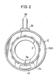
- a yoke 2 formed into a ring-like body and having a U-shaped section at a part thereof in the circumferential direction is fixed to the outer periphery on the nose (1a) side of a compressor housing 1 through a support plate 3.
- the support plate 3 is positioned relative to the housing 1 by a recess 1d and a protuberance 3a and its movement in the axial direction is restricted by a retaining ring 23.
- a coil bobbin 20 for accommodating an excitation coil 4 comprising a self-weldable wire is fitted into a ring-like groove 2a of this yoke 2.
- a ball bearing 5 is fitted into the nose portion 1a of the housing 1, and a snap ring 6 and a step portion 1b of the housing 1 restrict the movement in the axial direction.
- a ring-like rotor 7 having a ring-like groove 7a and a U-shaped section at a part thereof in the circumferential direction is forced into the outer race 5a of the ball bearing 5, and the step portion 7b and a plurality of caulking plates 7c restrict the movement in the axial direction.
- a plurality of V-shaped grooves 7d are made round the outer periphery of the rotor 7, and the rotation on the driving side is transmitted to the rotor through a V belt, not shown, which is stretched between the V-shaped grooves 7d and a driving source such as a car engine.
- a rotary shaft 8 is provided through a center hole 1c of the housing.
- This rotary shaft 8 is rotatably supported by a bearing, not shown, on the housing (1) side and protrudes outside from the nose portion 1a.
- An armature assembly 9 as a rotary member on the output side is fitted to the distal end of this protruding portion.
- the armature assembly 9 comprises an armature hub 10, a stopper plate 11, an armature 12, and associated components.
- the armature hub 10 comprises a boss 10a and a flange 10b formed integrally with this boss 10a.
- the boss 10a is spline-coupled with the distal end of the protruding portion of the rotary shaft 8 and is fixed with a bolt 13 and a doubling plate 14.
- the doubling plate 14 is prevented from coming off by a plurality of caulking plates 10c provided to the boss 10a.
- the stopper plate 11 described above is fixed to the outside surface of the flange 10b with a Plurality of headed rivets 15. This stopper plate 11 is formed by punching out a steel sheet into a substantial triangle when viewed from the front. A round through-hole 11a is bored at each vertex and at the same time, a damper cover 17 for accommodating a damper rubber 16 is welded to each vertex.
- the afore-mentioned armature 12 is fitted to the inside surface of the stopper plate 11.
- This armature 12 is fitted to the stopper plate 11 through the rivet 18 and the damper rubber 16 and is opposed to a friction surface 7e of the rotor 7 with a small gap G between them.
- the coil bobbin 20 for accommodating the excitation coil 4 comprises two members, that is, a bobbin main body 20A and a coil cover 20B, each of which is molded with a synthetic resin into a ring-like body so that a part thereof in the peripheral direction has a U-shaped section and whose opening is bonded to that of the other. These members 20A and 20B cover the excitation coil 4 and shield it from outside.
- the coil bobbin 20 is fitted into the ring-like groove 2a of the yoke 2 and is prevented from coming off from the ring-like groove 2a by a plurality of caulking plates 2b. As shown in Figs.
- the joint surfaces of the bobbin main body 20A and the coil cover 20B are formed into taper surfaces 19a and 19b that incline at the same angle but in mutually opposite directions.
- these taper surfaces are tightly fitted to each other by the wedge action, further reinforce fixing of the excitation coil 4 and completely shield the excitation coil 4 from outside.
- the outer peripheral surface 20a of the coil cover 20B is shaped into a slope that inclines towards the opening of the coil cover 20B and is forced into the ring-like groove 2a of the yoke 2.
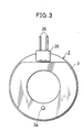
- a rectangular hole 21 through the bottom plate of the yoke 2 is bored at one position of the yoke 2, into which such a coil bobbin 20 is fitted, in the circumferential direction, and the accommodation section 22 formed integrally and protrusively from the outside surface of the bobbin main body 20A protrudes from this hole 21 to the outside of the yoke 2.
- this accommodation section 22 is constituted into a rectangular frame body extended in the circumferential direction of the bobbin main body 20A by four side plates 22a to 22d.
- a silicon diffused junction diode 24 as a varistor for absorbing a surge voltage that develops when the supply of the current to the excitation coil 4 is cut off is accommodated inside this frame body.
- Two terminals 27 (27A and 27B) having the same structure for connecting electrically this diode 24, the excitation coil 4 and lead wires 26 on the power source side are also accommodated in the frame body, and are covered with a terminal cover 28.
- the terminal cover 28 is fixed to the accommodation section 22 by ultrasonic fusing, or the like, in such a manner as to cover the frame body comprising the side plates 22a to 22d and the terminals 27A and 27B.
- a spacer 33 is fitted to the outer periphery of the accommodation section 22 and is fixed to it by ultrasonic welding, or the like.
- three side plates 22a, 22b and 22d have the same height but are higher than the side plate 22c on the external side.
- An engagement groove 27f of the terminals 27A and 27B is engaged with the side plate 22c, and the lead wire 26 on the power source side is clamped between the terminal cover 28 and the spacer 33.
- the center portion of the inner bottom surface 22e of the accommodation section 22 in the longitudinal direction is so formed as to be lower than both of its side portions, functions as the support surface of the diode 24 described above, and has two coil lead-out holes 29a and 29b communicating with the inside of the bobbin main body 20A. As shown in Figs. 4 and 6, these coil lead-out holes 29a and 29b are provided on one of the sides of the diode 24 and are spaced apart in the peripheral direction of the bobbin main body 20A. A winding start portion 4a and a winding end portion 4b of the excitation coil 4 are inserted through, and led out from these coil lead-out holes 29a and 29b, respectively. A groove 29c for leading out the coil is made in the portion on the inner surface side of the bobbin main body 20A, where the coil lead-out holes 29a and 29b are made, as shown in Figs. 9 and 10.
- Two grooves 30a and 30b into which the winding start portion and the winding end portion 4b of the excitation coil 4 are fitted, respectively, two grooves 31a and 31b into which the leads 24a and 24b of the diode 24 are fitted, respectively, and two grooves 32a and 32b into which the terminals 27A and 27B are forced, are made on both sides of the inner bottom surface 22e of the accommodation section 22.
- the grooves 30a, 30b for fitting the coil and the grooves 31a, 31b for fitting the lead are parallel to one another and are extended in the circumferential direction of the bobbin main body 20A.
- Each of the grooves 32a and 32b for fitting the two terminals comprises two grooves which are parallel to each other and is extended in the radial direction of the bobbin main body 20 in such a manner as to perpendicularly cross the grooves 30a and 30b for fitting the coil and the grooves 31a and 31b for fitting the leads.
- the upper surface of the step portion 22f that partitions the center portion of the inner bottom surface 22e of the accommodation section 22 from both side portions is curved arcuately as shown in Fig. 9, and the winding start portion 4a and the winding end portion 4b of the coil 4 are so bent as to extend along this arcuate step portion 22f and to be fitted into the grooves 30a and 30b for fitting the coil.
- the terminal 27 is so formed by bending a conductive metal plate such as of copper, brass, etc, that the section has a U shape as shown in Fig. 18.
- the terminal 27 includes integrally an oblong main body 27a, two side plate sections 27b and 27c so formed contiguously to one of the ends of the main body 27a as to be opposed to each other, and two side plate sections 27d and 27e so formed contiguously to the other end of the main body 27a as to be opposed to each other.
- Engagement grooves 27f are made between the side plate section 27b and the side plate section 27d and between the side plate section 27c and the side plate section 27e.
- Two grooves 34a and 34b into which each end portion (4a, 4b) of the excitation coil 4 and each lead 24a, 24b of the diode 24 are fitted are made in the end surface of each side plate section 27b, 27c, and a triangular engagement pawl 35 is formed integrally at each end in such a manner as to protrude therefrom.
- the grooves 34a into which the winding start portion 4a and the winding end portion 4b of the excitation coil 4 are fitted have edge shapes at their groove ends.
- the winding start and end edge portions break through the insulating film such as an enamel film insulating and covering the coil core wire and are clamped in the coil core wires when the winding start and end portions 4a, 4b are fitted, so that the coil core wires and the terminal 27 can be connected more reliably.
- the leads 24a and 24b of the diode 24 are not generally coated for insulation. Therefore, the groove end of the groove 34b need not be shaped into an edge.
- the engagement pawl 35 is between into the groove walls of the grooves 32a and 32b for fitting the terminal and prevents come-off of the terminal 27.
- the engagement pawl 35 abuts on the groove wall, the side plate sections 27b and 27c are compressed and narrow the grooves 34a and 34b. In consequence, the terminal 27 can be connected more reliably to the excitation coil 4 and the diode 24.
- the end portion of the core wire of the lead wire 26 on the power source side is extended along the lower surface of the main body 27a and is fitted between the side plate sections 27d and 27e, and when these side plate sections 27d and 27e are bent inward, they clamp the insulating portion of the lead wire 26 on the power source side, so that the lead wire 26 is fixed to the terminal 27 and is electrically connected thereto.
- the lead wires 26 on the positive and negative sides of the power source are connected in advance to the terminals 27A and 27B.
- the winding start portion 4a and the winding end portion of the excitation coil 4 led out from the coil lead-out holes 29a and 29b are bent outward and are fitted into the grooves 30a and 30b for fitting the coil, respectively.
- the leads 24a and 24b of the diode 24 are fitted into the lead fitting grooves 31a and 31b.
- the grooves 34a and 34b of the terminals 27A and 27B are brought into alignment with the grooves 30a, 30b for fitting the coil and the grooves 31a, 31b for fitting the leads, and the side plate sections 27b and 27c are fitted into the grooves 32a and 32b for fitting the terminals in order.
- the winding start portion 4a and the winding end portion 4b of the excitation coil 4 are inserted into the coil grooves 34a for the terminals 27A and 278, and are electrically connected to these terminals.
- the leads 24a and 24b of the diode 24 are fitted into the grooves 34b for the leads of the terminals 27A and 27B and are electrically connected to these terminals.
- the diode 24 is connected in parallel with the excitation coil 4.
- the surge voltage that develops when the supply of power to the excitation coil 4 is cut off can be absorbed.
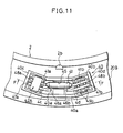
- an accommodation section 40 for accommodating a temperature fuse 41 and two terminals 42 (42A and 42B) for connecting this temperature fuse 41 in parallel with the excitation coil 4 is integrally formed at one position of the outside surface of the coil cover 20B constituting the coil bobbin 20 in its circumferential direction.
- This accommodation section 40 is constituted into a deformed rectangular frame body extended in the circumferential direction of the coil cover 20B by four side plates 40a to 40d, and is covered with a fuse cover 43. After the temperature fuse 41 is accommodated inside the accommodation section 40 and is connected to the excitation coil 4, the fuse cover 43 is fused by ultrasonic fusing, or the like.
- the accommodation section 40 is disposed at a position deviated by about 180° from the accommodation section 22 of the diode 24 in the circumferential direction.
- a fuse accommodation groove 45 for accommodating the temperature fuse 41 described above and two coil lead-out holes 46a and 46b are made at the center of the inner bottom surface 40e of the accommodation section 40 in its longitudinal direction.
- the fuse accommodation groove 45 is extended in the longitudinal direction of the accommodation section 40 and restricts the movement of the temperature fuse 41 in the radial direction of the coil cover 20B.
- the coil lead-out holes 46a and 46b are positioned on one of the sides of the temperature fuse 41 and are spaced apart from each other in the longitudinal direction of the fuse accommodation groove 45. Further, they communicate with the inside of the coil cover 20B.
- the excitation coil 4 is assembled into the coil bobbin 20.
- a deflection portion is formed while the coil is being wound, and is cut at its center so as to form the two cut end portions 4c and 4d.
- the coil is further wound to form the excitation coil 4.
- the cut end portions 4c and 4d are exposed to one of the side surfaces of the excitation coil 4 in this state.
- the excitation coil 4 so wound up is fitted into the bobbin main body 20A.
- the coil cover 20B is put on the portion of the excitation coil 4 protruding from the bobbin main body 20A.
- the cut end portions 4c and 4d are led into the accommodation section 40 through the coil lead-out holes 46a and 46b.
- the coil bobbin 20 is fitted into the ring-like groove 2a of the yoke 2 to constitute the yoke assembly, and is fixed to the housing 1.
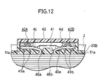
- Both sides of the inner bottom surface 40e of the accommodation section 40 are so shaped as to be higher than the center portion, and two coil engagement grooves 47a and 47b into which the cut end portions 4c and 4d are fitted, two lead engagement grooves 48a and 48b into which the leads 41a and 41b of the temperature fuse 41 are fitted and two terminal grooves 49a and 49b into which the terminals 42A and 42B are fitted are made in the both sides of the inner bottom surface 40e.
- the coil engagement grooves 47a, 47b and the lead engagement grooves 48a, 48b are parallel to one another and are extended in the circumferential direction of the coil cover 20B.
- Each of the two terminal engagement grooves 49a and 49b comprises two mutually parallel grooves and are provided in the radial direction of the coil cover 20B in such a manner as to perpendicularly cross the lead engagement grooves 48a and 48b.
- the terminal 42 is formed by bending a conductive metal plate such as of copper or brass, so that its section has a U-shape like the terminal 27, as shown in Fig. 19, and integrally includes an oblong main body 42a and two side plate sections 42b and 42c that are contiguous to both side edges of the main body 42a and opposed to each other.
- Two grooves 51a and 51b into which the cut end portion 4c, 4d of the excitation coil 4 and the lead 41a, 41b of the temperature fuse 41 are fitted are made in the distal end surface of each of the side plate sections 42b and 42c, and a triangular engagement pawl 52 is integrally formed on each of the side edges.
- the groove end of the groove 51a of the terminal 42 is shaped into an edge like the groove 34a of the terminal 27 described already so that when each cut end portion 4c, 4d of the excitation coil 4 is fitted, the edge breaks through the insulating film such as enamel covering and insulating the coil core wire and electrically connects the coil core wire to the terminal 42.
- the groove end need not be shaped into an edge by merely setting the groove width of the groove 51b to be somewhat smaller than the coil diameter.
- the engagement pawl 52 is caught between the groove wall of each terminal engagement groove when each side plate section 42b, 42c is forced into the terminal engagement groove 49a, 49b, and prevents come-off of the terminal 42.
- the cut end portions 4c and 4d of the excitation coil 4 are bent and are fitted into the coil engagement grooves 47a and 47b, respectively.
- the leads 41a and 41b of the temperature fuse 41 are fitted into the lead engagement grooves 48a and 48b, respectively.
- the grooves 51a and 51b of the terminals 42A and 42B are brought into alignment with the coil engagement grooves 47a and 47b and with the lead engagement grooves 48a and 48b, and the side plate sections 42b and 42c of the terminals 42A and 42B are serially forced into the terminal engagement grooves 49a and 49b, respectively.
- the cut end portions 4c and 4d of the excitation coil 4 are fitted into the coil grooves 51a of the terminals 42A and 42B and are electrically connected to these terminals 42.
- the leads 41a and 41b of the temperature fuse 41 are likewise fitted into the lead grooves 51b of the terminals 42A and 42B and are electrically connected to these terminals 42.
- the temperature fuse 41 connected the cut end portions 4c and 4d of the excitation coil 4 and is connected in series with this coil 4.
- this embodiment is an example where the temperature fuse 41 is used as a protective device of the solenoid clutch when the rotary shaft 8 of the compressor is locked, and the supply of power to the excitation coil 4 is cut off as the temperature fuse 41 is fused by the heat.
- this example is not particularly limitative and it is also possible to dispose a switch which cuts off the supply of power to the excitation coil 4 by using a heat-sensitive device such as a bimetal whose shape changes with the temperature rise.
- a heat-sensitive device such as a bimetal whose shape changes with the temperature rise.
- this embodiment uses a silicon diffused junction diode as the varistor for absorbing the surge voltage, another surge voltage absorption component may be used, as well.
- the armature coil 12 is magnetically attracted to the friction surface 7e of the rotor 7 when the excitation coil 4 is excited by the supply of power.
- a magnetic circuit is so formed as to extend from the yoke 2 to the external poles of the rotor 7 and then through the armature, and to return to the yoke 2 through the internal poles of the yoke 2. Therefore, the armature 12 is attracted to the rotor 7 against the elastic repulsion of the damper rubber 16.
- the armature 12 rotates integrally with the rotor 7, the rotary shaft 8 which is integrated with the armature 12 rotates and the air compressor is operated.
- the armature 12 is separated from the rotor 7 by the elastic repulsion of the damper rubber 16 and returns to the original position shown in Fig. 1, so that the transmission of revolution is cut off and the rotation of the rotary shaft 8 stops.
- the winding start portion 4a and the winding end portion 4b of the excitation coil 4 are led out in advance into the accommodation section 22 provided on the outside surface of the bobbin main body 20A and are fitted into the coil engagement grooves 30a and 30b, respectively.
- the leads 24a and 24b of the diode 24 are fitted in advance into the lead engagement grooves 31a and 31b.
- connection work between the excitation coil 4 and the diode 24 can be easily carried out without the necessity for soldering.
- the winding start portion 4a and the winding end portion 4b of the excitation coil 4 are fitted into the coil grooves 34a of the terminal 27, the groove end of the groove 34a shaped into an edge bites into the insulating film insulating and covering the coil core wire. Therefore, it is not necessary to remove in advance the insulating film, and the coil core wire and the terminal 27 can be reliably connected. Since the terminal 27 is equipped integrally with the engagement pawl 35, it does not come off from the terminal engagement groove 32a, 32b.
- the kind and the number of the terminals 27 can be reduced in comparison with the afore-mentioned prior art invention 1. Therefore, the size of the accommodation section 22 can be economically reduced.
- the cut end portions 4c and 4d of the excitation coil 4 are forced in advance into the accommodation section 40 of the coil cover 20B and are fitted into the coil engagement grooves 47a and 47b, and the leads 41a and 41b of the temperature fuse 41 are in advance fitted into the lead engagement grooves 48a and 48b.
- the two terminals 42 (42A and 42B) are forced into the terminal engagement grooves 49a and 49b in order.
- the cut end portions 4c and 4d of the excitation coil 4 can be electrically connected to the leads 41a and 41b of the temperature fuse 41. Therefore, the connection of the excitation coil 4 and the temperature fuse 41 can be carried out more easily than the prior art invention 2 without the necessity for soldering.
- the groove end of the groove 51a having an edge shape breaks through the insulating film of the excitation coil 4 and bites into the coil core wire. Therefore, the coil core wire and the terminal 42 can be electrically connected. In other words, the insulating film need not be removed and the connection work becomes easier. Since the fuse cover 43 covers the accommodation section 40, it is not necessary to mold the accommodation section 40 with synthetic resin, as in the prior art invention 3 and the temperature fuse 41 can be easily protected.
- the terminal 42 is equipped integrally with the engagement pawl 52, it does not easily come off from the terminal engagement groove 49a, 49b.
- the embodiment described above is an example of the application of the present invention to the solenoid clutch.
- the present invention can also be applied to a solenoid brake which allows the armature to be attracted directly and magnetically to the yoke, and can obtain similar effects.
- the electromagnetic coupling device has a structure wherein the yoke 2 is not fully fitted into the ring-like groove 7a of the rotor 7, the accommodation section 22 of the coil bobbin 20 may protrude from the outer peripheral surface of the yoke 2 and the lead-out direction of the lead wire 26 on the power source side may be any direction.
- the electromagnetic coupling device hereinbefore described includes a coil bobbin disposed inside a ring-like groove of the yoke, for supporting an excitation coil, an accommodation section disposed integrally with this coil bobbin, for accommodating an electric component, and two terminals accommodated in this accommodation section, for electrically connecting the excitation coil and the electric component, wherein each terminal is U-shaped, grooves are made in the two, mutually facing side plate sections so that the end portions of the excitation coil and the leads of the electric component can be fitted into them, the coil engagement grooves into which the end portions of the excitation coil are fitted, the lead engagement grooves into which the leads of the electric component are fitted and the terminal engagement grooves into which the side plate sections of the terminals are fitted are made in the inner bottom surface of the accommodation section.
- a varistor is used as the electric component and is connected in parallel with the excitation coil, the surge voltage developing when the supply of power to the excitation coil is absorbed and damage of the electric circuit can be prevented.
- the temperature fuse or the heat-sensitive device is used as the electric component and is connected in series with the excitation coil, the supply of power to the excitation coil is cut off to separate the rotor from the armature when the rotary member on the output side does not rotate for some reason or other. Therefore, damage of the device due to heat generation or breakage of the V belt can be prevented.
- the engagement pawl is provided integrally to the terminal, come-off of the terminals from the terminal engagement grooves can be reliably prevented.
Landscapes
- Engineering & Computer Science (AREA)
- General Engineering & Computer Science (AREA)
- Physics & Mathematics (AREA)
- Electromagnetism (AREA)
- Mechanical Engineering (AREA)
- Power Engineering (AREA)
- Electromagnets (AREA)
- Braking Arrangements (AREA)
Claims (14)
- Elektromagnetische Kupplungsvorrichtung mit:einem Spulenkörper bzw. -kern (20), der in einer ringartigen Nut (2a) eines Jochs bzw. Bügels (2) angeordnet ist, wobei eine Erregerspule (4) in der Spule gehalten ist,einem Aufnahmeabschnitt (22 oder 40), der integral mit dem Spulenkörper (20) gebildet ist,einer elektrischen Komponente (24 oder 41), die in dem Aufnahmeabschnitt aufgenommen ist, undzwei Anschlüssen (27 oder 42), die in dem Aufnahmeabschnitt (22 oder 40) zum elektrischen Verbinden der Erregerspule (4) und der elektrischen Komponente (24 oder 41) angeordnet ist, wobei:jeder der Anschlüsse (27 oder 42) U-förmig in der longitudinalen Richtung ist,Nuten (34a, 34b oder 51a, 51b), in die Endteilstücke (4a, 4b oder 4c, 4d) der Erregerspule (4) bzw. die Zuleitungen (24a, 24b oder 41a, 41b) der elektrischen Komponente (24 oder 41) eingepasst sind, in zwei Seitenplattenabschnitten (27b, 27c oder 42b, 42c) aneinander gegenüberliegend gefertigt sind, um gegenüberliegende Seiten des U-förmigen Anschlusses zu bilden, und der Aufnahmeabschnitt (22 oder 40) aufweist:Spuleneingriffnuten (30a, 30b oder 47a, 47b), in die die Endteilstücke (4a, 4b oder 4c, 4d) der Erregerspule (4) eingepasst sind,Zuleitungseingriffnuten (31a, 31b oder 48a, 48b), mit denen die Zuleitungen (24a, 24b oder 41a, 41b) der elektrischen Komponente (24 oder 41) im Eingriff sind, und Anschlusseingriffnuten (32a, 32b oder 49a, 49b), in die die Seitenplattenabschnitte (27b, 27c oder 42b, 42c) des Anschlusses (27 oder 42) jeweils eingepasst sind.
- Elektromagnetische Kupplungsvorrichtung nach Anspruch 1, bei der die elektrische Komponente eine Temperatursicherung (41) ist und in Reihe mit der Erregerspule (4) verbunden ist.
- Elektromagnetische Kupplungsvorrichtung nach Anspruch 1, bei der die elektrische Komponente eine wärmeempfindliche Vorrichtung (41) ist und in Reihe mit der Erregerspule (4) verbunden ist.
- Elektromagnetische Kupplungsvorrichtung nach Anspruch 1, bei der die elektrische Komponente ein Varistor (24) ist und parallel zu der Erregerspule (4) verbunden ist, wobei ein Zuleitungsdraht (26) mit jedem Anschluss (27) verbunden ist.
- Elektromagnetische Kupplungsvorrichtung nach einem der vorstehenden Ansprüche, die weiterhin Spulenanschluss- bzw. - auslasslöcher (29a, 29b oder 46a, 46b) aufweist, durch die die Endteilstücke (4a, 4b oder 4c, 4d) der Erregerspule (4) bei Gebrauch angeschlossen bzw. ausgelassen sind.
- Elektromagnetische Kupplungsvorrichtung nach einem der vorstehenden Ansprüche, bei der die Anschlusseingriffnuten, in die die Seitenplattenabschnitte des Anschlusses eingepasst sind, in der inneren Bodenoberfläche des Aufnahmeabschnitts gefertigt sind.
- Elektromagnetische Kupplungsvorrichtung mit:einer Erregerspule (4),einem Spulenhauptkörper (20A), zu dem die Erregerspule (4) angepasst ist,einem ersten Aufnahmeabschnitt (22), der integral mit dem Spulenhauptkörper (20A) gebildet ist,Wickelstart- und -endteilstücken (4a, 4b) der Erregerspule (4), die von einer inneren Bodenoberfläche (22e) des ersten Aufnahmeabschnitts (22) ausgelassen sind,einer ersten elektrischen Komponente (24), die in dem ersten Aufnahmeabschnitt (22) aufgenommen ist,einem Paar von ersten Anschlüssen (27), die in dem ersten Aufnahmeabschnitt (22) aufgenommen sind, um die Wickelstart- und -endteilstücke (4a, 4b) und Zuleitungen (24a, 24b) der ersten elektrischen Komponente (24) zu verbinden,einer Anschlussabdeckung (28), die an dem ersten Aufnahmeabschnitt (22) befestigt ist,einer Spulenabdeckung (20B), die auf die Erregerspule (4) gesetzt ist, die von dem Spulenhauptkörper (20A) vorsteht,einem zweiten Aufnahmeabschnitt (40), der integral zu der Spulenabdeckung (20B) vorgesehen ist,Schnittendteilstücken (4c, 4d) der Erregerspule (4), die von einer inneren Bodenoberfläche (40e) des zweiten Aufnahmeabschnitts (40) ausgelassen sind,einer zweiten elektrischen Komponente (41), die in dem zweiten Aufnahmeabschnitt (40) aufgenommen ist,einem Paar von zweiten Anschlüssen (42), die in dem zweiten Aufnahmeabschnitt (40) aufgenommen sind, um die Schnittendteilstücke (4c, 4d) und Zuleitungen (41a, 41b) der zweiten elektrischen Komponente (21) zu verbinden,einer Sicherungsabdeckung (43), die an dem zweiten Aufnahmeabschnitt (40) befestigt ist, undeinem Joch (2), das an dem Boden davon ein Durchgangsloch (21) aufweist, in das der erste Aufnahmeabschnitt (22) eingepasst ist, und eine ringartige Nut (2a), in die der Spulenhauptkörper (20A) und die Spulenabdeckung (20B) eingepasst sind.
- Elektromagnetische Kupplungsvorrichtung nach Anspruch 7, bei der:die Wicklungsstartendteilstücke (4a, 4b) symmetrisch nach außen gebogen sind,die erste elektrische Komponente (24) Zuleitungen (24a, 24b) davon hat, die parallel zu den Wickelstart- und -endteilstücken (4a, 4b) angeordnet sind,die Schnittendteilstücke (4c, 4d) symmetrisch nach außen gebogen sind, unddie zweite elektrische Komponente (41) Zuleitungen (41a, 41b) davon aufweist, die parallel zu den Schnittendteilstücken (4c, 4d) der Erregerspule (4) angeordnet sind.
- Elektromagnetische Kupplungsvorrichtung nach Anspruch 7, bei der:jeder der Anschlüsse (27 oder 42) U-förmig ist,Nuten (34a, 34b oder 51a, 51b), in die die Endteilstücke (4a, 4b oder 4c, 4d) der Erregerspule (4) und die Zuleitungen (24a, 24b oder 41a, 41b) der elektrischen Komponente (24 oder 41) eingepasst sind, in zwei Seitenplattenabschnitten (27b, 27c oder 42b, 42c), die einander gegenüberliegen, vorgesehen sind, undjeder der Aufnahmeabschnitte (22 oder 40) mit Spulenauslasslöchern (29a, 29b oder 46a, 46b) ausgestattet ist, durch die die Endteilstücke (4a, 4b oder 4c, 4d) der Erregerspule (4) ausgelassen sind, Spuleneingriffnuten (30a, 30b oder 47a, 47b), in die die Endteilstücke (4a, 4b oder 4c, 4d) der Erregerspule (4) eingepasst sind, Zuleitungseingriffnuten (31a, 31b oder 48a, 48b), in die die Zuleitungen (24a, 24b oder 41a, 41b) der elektrischen Komponente (24 oder 41) eingepasst sind, und Anschlusseingriffnuten (32a, 32b oder 49a, 49b) in die die Seitenplattenabschnitte (27b, 27c oder 42b, 42c) des Anschlusses (27 oder 42) eingepasst sind.
- Elektromagnetische Kupplungsvorrichtung nach Anspruch 9, bei der:die Anschlusseingriffnuten (32a, 32b oder 49a, 49b), in die die Seitenplattenabschnitte (27b, 27c oder 42b, 42c) des Anschlusses (27 oder 42) senkrecht quer zu den Spuleneingriffnuten (30a, 30b oder 47a, 47b) und den Zuleitungseingriffnuten (31a, 31b oder 41a, 41b) eingepasst sind.
- Elektromagnetische Kupplungsvorrichtung nach Anspruch 7 oder 8, bei der die zweite elektrische Komponente eine Temperatursicherung (41) ist und in Reihe mit der Erregerspule (4) verbunden ist.
- Elektromagnetische Kupplungsvorrichtung nach Anspruch 7 oder 8, bei der die zweite elektrische Komponente eine wärmeempfindliche Vorrichtung (41) ist und in Reihe mit der Erregerspule (4) verbunden ist.
- Elektromagnetische Kupplungsvorrichtung nach Anspruch 7 oder 8, bei der die erste elektrische Komponente ein Varistor (24) ist und parallel zu der Erregerspule (4) verbunden ist, und ein Zuleitungsdraht (26) auf der Energie- bzw. Stromquellenseite mit dem ersten Anschluss (27) verbunden ist.
- Elektromagnetische Kupplungsvorrichtung nach Anspruch 13, bei der der erste Anschluss (27) ein Verdrahtungsteilstück aufweist, bei dem die beiden Seitenplattenabschnitte (27b, 27c) zum Verbinden der Wickelstart- und - endteilstücke (4a, 4b) und die Zuleitungen (24a, 24b) der ersten elektrischen Komponente (24) angeordnet sind, ein Klemmteilstück, bei dem die beiden Seitenplattenabschnitte (27d, 27e) zum Verbinden der Zuleitungsdrähte (26) auf der Stromquellenseite angeordnet sind, und eine Eingriffnut (27f), die zwischen dem Verdrahtungateilatück und dem Klemmteilstück gefertigt ist, wobei die Eingriffnut (27f) in Eingriff mit der Seitenplatte (22c) des ersten Aufnahmeabschnitts (22) ist.
Applications Claiming Priority (3)
| Application Number | Priority Date | Filing Date | Title |
|---|---|---|---|
| JP08193119A JP3099288B2 (ja) | 1996-07-23 | 1996-07-23 | 電磁連結装置 |
| JP19311996 | 1996-07-23 | ||
| JP193119/96 | 1996-07-23 |
Publications (2)
| Publication Number | Publication Date |
|---|---|
| EP0821176A1 EP0821176A1 (de) | 1998-01-28 |
| EP0821176B1 true EP0821176B1 (de) | 2004-11-03 |
Family
ID=16302583
Family Applications (1)
| Application Number | Title | Priority Date | Filing Date |
|---|---|---|---|
| EP97305509A Expired - Lifetime EP0821176B1 (de) | 1996-07-23 | 1997-07-23 | Elektromagnetische Kupplungsvorrichtung |
Country Status (4)
| Country | Link |
|---|---|
| US (1) | US5936501A (de) |
| EP (1) | EP0821176B1 (de) |
| JP (1) | JP3099288B2 (de) |
| DE (1) | DE69731431D1 (de) |
Families Citing this family (24)
| Publication number | Priority date | Publication date | Assignee | Title |
|---|---|---|---|---|
| JP3925880B2 (ja) * | 1998-01-19 | 2007-06-06 | 小倉クラッチ株式会社 | 電磁クラッチ |
| JP3422971B2 (ja) * | 2000-05-25 | 2003-07-07 | 小倉クラッチ株式会社 | 電磁クラッチ |
| JP2003130087A (ja) * | 2001-10-30 | 2003-05-08 | Sanden Corp | 電磁クラッチ用ヨーク |
| KR100547042B1 (ko) * | 2003-03-27 | 2006-01-31 | 우리산업 주식회사 | 방전소자부의 내장형 설치구조 및 설치방법 |
| JP4473042B2 (ja) * | 2004-05-26 | 2010-06-02 | 株式会社ジェイテクト | トルク検出装置、ワイヤーハーネス、電動パワーステアリング装置及び端子ホルダ |
| US7975818B2 (en) * | 2005-06-10 | 2011-07-12 | Warner Electric Technology Llc | Rotational coupling device |
| JP2008300783A (ja) * | 2007-06-04 | 2008-12-11 | Hamanako Denso Co Ltd | 電磁ソレノイド装置 |
| KR101141964B1 (ko) | 2007-08-21 | 2012-05-04 | 우리산업 주식회사 | 전자클러치의 필드코일 어셈블리 |
| KR101152019B1 (ko) * | 2009-01-16 | 2012-06-08 | 우리산업 주식회사 | 압축기용 전자클러치의 필드코일 어셈블리 및 이의 제조방법 |
| JP5600034B2 (ja) | 2009-08-28 | 2014-10-01 | 小倉クラッチ株式会社 | 電磁連結装置 |
| JP5447122B2 (ja) * | 2010-04-13 | 2014-03-19 | 株式会社デンソー | 電磁スイッチ |
| JP2013164149A (ja) * | 2012-02-13 | 2013-08-22 | Denso Corp | 電磁クラッチ |
| JP5720652B2 (ja) * | 2012-10-17 | 2015-05-20 | 株式会社デンソー | 内燃機関用点火コイル |
| JP5995655B2 (ja) * | 2012-10-23 | 2016-09-21 | 小倉クラッチ株式会社 | 電磁連結装置 |
| JP2014209022A (ja) * | 2013-03-29 | 2014-11-06 | サンデン株式会社 | 電磁クラッチ及び電磁クラッチの製造方法 |
| JP5894123B2 (ja) | 2013-07-17 | 2016-03-23 | トヨタ自動車株式会社 | 電磁コイル装置 |
| CN103603887A (zh) * | 2013-10-25 | 2014-02-26 | 安徽工贸职业技术学院 | 一种离合器导线绕组 |
| KR101519265B1 (ko) * | 2013-12-18 | 2015-05-11 | 현대자동차주식회사 | 차량의 사운드제너레이터 |
| EP3087270B1 (de) * | 2013-12-27 | 2021-08-11 | Robert Bosch Motores de Partida e Alternadores Ltda. | Anlasser-motor-magnetventil |
| JP6277781B2 (ja) * | 2014-02-28 | 2018-02-14 | 株式会社デンソー | 電磁クラッチおよびその電磁クラッチの製造方法 |
| JP6332000B2 (ja) * | 2014-12-05 | 2018-05-30 | 株式会社デンソー | 電磁クラッチ |
| JP6176345B2 (ja) * | 2016-03-01 | 2017-08-09 | 株式会社デンソー | 電磁クラッチの製造方法 |
| JP6917156B2 (ja) * | 2017-02-17 | 2021-08-11 | 日立Astemo上田株式会社 | コイル組立体およびブレーキ制御装置 |
| JP7034350B1 (ja) * | 2021-03-08 | 2022-03-11 | 三菱電機株式会社 | 電磁マグネット、電磁ブレーキ、及びエレベータ巻上機 |
Citations (1)
| Publication number | Priority date | Publication date | Assignee | Title |
|---|---|---|---|---|
| EP0806583A1 (de) * | 1996-05-07 | 1997-11-12 | Sanden Corporation | Elektromagnetische Kupplung |
Family Cites Families (25)
| Publication number | Priority date | Publication date | Assignee | Title |
|---|---|---|---|---|
| US4181393A (en) * | 1978-03-17 | 1980-01-01 | Amp Incorporated | Interconnecting means for coil windings and overload protector |
| JPS56138529A (en) * | 1980-03-31 | 1981-10-29 | Hitachi Ltd | Electromagnetic clutch |
| US4432446A (en) * | 1980-06-28 | 1984-02-21 | Nippondenso Co., Ltd. | Electromagnetic coupling apparatus |
| JPS5751026A (en) * | 1980-09-10 | 1982-03-25 | Hitachi Ltd | Surge absorber for magnetic clutch |
| JPS5751025A (en) * | 1980-09-10 | 1982-03-25 | Hitachi Ltd | Fitting part for temperature fuse of magnetic clutch |
| JPS5913137A (ja) * | 1982-07-12 | 1984-01-23 | Nissan Motor Co Ltd | 自動車空調用電磁クラツチ装置 |
| JPS59144825A (ja) * | 1983-02-08 | 1984-08-20 | Matsushita Electric Ind Co Ltd | 電磁クラツチの保護装置 |
| JPS6012732U (ja) | 1983-07-07 | 1985-01-28 | サンデン株式会社 | 電磁クラツチ |
| US4557544A (en) * | 1984-12-17 | 1985-12-10 | Amp Incorporated | Terminal for connecting a lead wire to a coil wire |
| US4897758A (en) * | 1985-05-20 | 1990-01-30 | Eaton Corporation | Protecting an icemaker against over current damage |
| JPH0719685B2 (ja) * | 1986-07-03 | 1995-03-06 | 日本電装株式会社 | 電磁クラッチのコイル接続構造 |
| US4945329A (en) * | 1987-01-28 | 1990-07-31 | Mitsubishi Denki Kabushiki Kaisha | Tripping device with burning prevention switch |
| DE3816965C2 (de) * | 1988-05-18 | 1993-11-04 | Zinser Textilmaschinen Gmbh | Vorrichtung zur ermittlung von fadenbruch bei einer ringspinn- oder zwirnmaschine |
| JPH0238105A (ja) * | 1988-07-29 | 1990-02-07 | Suzuki Motor Co Ltd | 自動車のリヤサスペンション装置 |
| US5307038A (en) * | 1989-03-28 | 1994-04-26 | Ogura Clutch Co., Ltd. | Electromagnetic coupling apparatus |
| US4935713A (en) * | 1989-06-12 | 1990-06-19 | Ford Motor Company | Field coil assembly for an electromagnetically actuated clutch |
| US5225801A (en) * | 1990-04-28 | 1993-07-06 | Toyo Denso Kabushiki Kaisha | Ignition coil device for engine |
| US5184705A (en) * | 1990-07-16 | 1993-02-09 | Ogura Corporation | Electromagnetic clutch |
| JP2663364B2 (ja) | 1990-09-17 | 1997-10-15 | 小倉クラッチ株式会社 | 電磁連結装置 |
| US5138293A (en) * | 1990-09-17 | 1992-08-11 | Ogura Clutch, Co., Ltd. | Terminal connection structure of electromagnetic coupling device |
| US5320206A (en) * | 1993-05-03 | 1994-06-14 | Ogura Corporation | Coil mounting and terminals for an electromagnetic clutch |
| JPH07127662A (ja) * | 1993-11-02 | 1995-05-16 | Nippondenso Co Ltd | 電磁クラッチ |
| JP3254852B2 (ja) * | 1993-11-04 | 2002-02-12 | 株式会社デンソー | 電磁クラッチのコネクタ一体ステータにおけるスプールと端子との結合方法 |
| JP3498355B2 (ja) * | 1994-04-28 | 2004-02-16 | 株式会社デンソー | 電磁クラッチ |
| US5508671A (en) * | 1994-08-09 | 1996-04-16 | Qgura Clutch Co., Ltd. | Electromagnetic coupling device |
-
1996
- 1996-07-23 JP JP08193119A patent/JP3099288B2/ja not_active Expired - Fee Related
-
1997
- 1997-07-17 US US08/896,093 patent/US5936501A/en not_active Expired - Lifetime
- 1997-07-23 EP EP97305509A patent/EP0821176B1/de not_active Expired - Lifetime
- 1997-07-23 DE DE69731431T patent/DE69731431D1/de not_active Expired - Lifetime
Patent Citations (1)
| Publication number | Priority date | Publication date | Assignee | Title |
|---|---|---|---|---|
| EP0806583A1 (de) * | 1996-05-07 | 1997-11-12 | Sanden Corporation | Elektromagnetische Kupplung |
Also Published As
| Publication number | Publication date |
|---|---|
| JP3099288B2 (ja) | 2000-10-16 |
| EP0821176A1 (de) | 1998-01-28 |
| DE69731431D1 (de) | 2004-12-09 |
| US5936501A (en) | 1999-08-10 |
| JPH1037978A (ja) | 1998-02-13 |
Similar Documents
| Publication | Publication Date | Title |
|---|---|---|
| EP0821176B1 (de) | Elektromagnetische Kupplungsvorrichtung | |
| US5307038A (en) | Electromagnetic coupling apparatus | |
| US5967282A (en) | Electromagnetic coupling device | |
| JP3743113B2 (ja) | 回転電機 | |
| US5508671A (en) | Electromagnetic coupling device | |
| JP5600034B2 (ja) | 電磁連結装置 | |
| JP3837786B2 (ja) | 電磁クラッチ | |
| JP3207717B2 (ja) | コイルボビン及び励磁コイル | |
| JPH11166562A (ja) | 電磁連結装置 | |
| JP3925880B2 (ja) | 電磁クラッチ | |
| JPH07127662A (ja) | 電磁クラッチ | |
| JPH11270589A (ja) | コネクタ一体型コイル装置 | |
| JP2663364B2 (ja) | 電磁連結装置 | |
| JP2002039214A (ja) | 電磁クラッチ | |
| KR200382537Y1 (ko) | 보빈어셈블리및이것을이용한전자석클러치 | |
| KR101162057B1 (ko) | 압축기용 전자클러치의 필드코일 조립체 | |
| JPH085385Y2 (ja) | 電磁連結装置の励磁装置 | |
| KR200353562Y1 (ko) | 전자석 클러치의 필드코어 어셈블리 | |
| JPS636512Y2 (de) | ||
| KR200162259Y1 (ko) | 압축기의 전자클러치 온도감지장치 | |
| KR200279354Y1 (ko) | 전자클러치 | |
| JPH0441741Y2 (de) | ||
| JP2001124098A (ja) | 軸受の組み付け構造 | |
| JP2006292010A (ja) | 温度ヒューズ固定用ホルダー、コイルボビン及び電磁クラッチ | |
| JP3186467B2 (ja) | 電磁連結装置 |
Legal Events
| Date | Code | Title | Description |
|---|---|---|---|
| PUAI | Public reference made under article 153(3) epc to a published international application that has entered the european phase |
Free format text: ORIGINAL CODE: 0009012 |
|
| AK | Designated contracting states |
Kind code of ref document: A1 Designated state(s): AT BE CH DE DK ES FI FR GB GR IE IT LI LU MC NL PT SE |
|
| AX | Request for extension of the european patent |
Free format text: AL;LT;LV;RO;SI |
|
| 17P | Request for examination filed |
Effective date: 19980507 |
|
| 17Q | First examination report despatched |
Effective date: 19980702 |
|
| RBV | Designated contracting states (corrected) |
Designated state(s): BE DE ES FR GB IT PT |
|
| GRAP | Despatch of communication of intention to grant a patent |
Free format text: ORIGINAL CODE: EPIDOSNIGR1 |
|
| GRAS | Grant fee paid |
Free format text: ORIGINAL CODE: EPIDOSNIGR3 |
|
| GRAA | (expected) grant |
Free format text: ORIGINAL CODE: 0009210 |
|
| AK | Designated contracting states |
Kind code of ref document: B1 Designated state(s): BE DE ES FR GB IT PT |
|
| PG25 | Lapsed in a contracting state [announced via postgrant information from national office to epo] |
Ref country code: IT Free format text: LAPSE BECAUSE OF FAILURE TO SUBMIT A TRANSLATION OF THE DESCRIPTION OR TO PAY THE FEE WITHIN THE PRE;WARNING: LAPSES OF ITALIAN PATENTS WITH EFFECTIVE DATE BEFORE 2007 MAY HAVE OCCURRED AT ANY TIME BEFORE 2007. THE CORRECT EFFECTIVE DATE MAY BE DIFFERENT FROM THE ONE RECORDED.SCRIBED TIME-LIMIT Effective date: 20041103 Ref country code: BE Free format text: LAPSE BECAUSE OF FAILURE TO SUBMIT A TRANSLATION OF THE DESCRIPTION OR TO PAY THE FEE WITHIN THE PRESCRIBED TIME-LIMIT Effective date: 20041103 |
|
| REG | Reference to a national code |
Ref country code: GB Ref legal event code: FG4D |
|
| REF | Corresponds to: |
Ref document number: 69731431 Country of ref document: DE Date of ref document: 20041209 Kind code of ref document: P |
|
| PG25 | Lapsed in a contracting state [announced via postgrant information from national office to epo] |
Ref country code: DE Free format text: LAPSE BECAUSE OF FAILURE TO SUBMIT A TRANSLATION OF THE DESCRIPTION OR TO PAY THE FEE WITHIN THE PRESCRIBED TIME-LIMIT Effective date: 20050204 |
|
| PG25 | Lapsed in a contracting state [announced via postgrant information from national office to epo] |
Ref country code: ES Free format text: LAPSE BECAUSE OF FAILURE TO SUBMIT A TRANSLATION OF THE DESCRIPTION OR TO PAY THE FEE WITHIN THE PRESCRIBED TIME-LIMIT Effective date: 20050214 |
|
| PG25 | Lapsed in a contracting state [announced via postgrant information from national office to epo] |
Ref country code: GB Free format text: LAPSE BECAUSE OF NON-PAYMENT OF DUE FEES Effective date: 20050723 |
|
| PLBE | No opposition filed within time limit |
Free format text: ORIGINAL CODE: 0009261 |
|
| STAA | Information on the status of an ep patent application or granted ep patent |
Free format text: STATUS: NO OPPOSITION FILED WITHIN TIME LIMIT |
|
| 26N | No opposition filed |
Effective date: 20050804 |
|
| ET | Fr: translation filed | ||
| GBPC | Gb: european patent ceased through non-payment of renewal fee |
Effective date: 20050723 |
|
| PG25 | Lapsed in a contracting state [announced via postgrant information from national office to epo] |
Ref country code: PT Free format text: LAPSE BECAUSE OF NON-PAYMENT OF DUE FEES Effective date: 20050403 |
|
| PGFP | Annual fee paid to national office [announced via postgrant information from national office to epo] |
Ref country code: FR Payment date: 20140723 Year of fee payment: 18 |
|
| REG | Reference to a national code |
Ref country code: FR Ref legal event code: ST Effective date: 20160331 |
|
| PG25 | Lapsed in a contracting state [announced via postgrant information from national office to epo] |
Ref country code: FR Free format text: LAPSE BECAUSE OF NON-PAYMENT OF DUE FEES Effective date: 20150731 |