EP0824273A2 - Solar battery module and roofing material incorporating it - Google Patents
Solar battery module and roofing material incorporating it Download PDFInfo
- Publication number
- EP0824273A2 EP0824273A2 EP97113707A EP97113707A EP0824273A2 EP 0824273 A2 EP0824273 A2 EP 0824273A2 EP 97113707 A EP97113707 A EP 97113707A EP 97113707 A EP97113707 A EP 97113707A EP 0824273 A2 EP0824273 A2 EP 0824273A2
- Authority
- EP
- European Patent Office
- Prior art keywords
- reinforcing sheet
- junction boxes
- solar battery
- photovoltaic element
- spacer members
- Prior art date
- Legal status (The legal status is an assumption and is not a legal conclusion. Google has not performed a legal analysis and makes no representation as to the accuracy of the status listed.)
- Withdrawn
Links
Images


Classifications
-
- H—ELECTRICITY
- H02—GENERATION; CONVERSION OR DISTRIBUTION OF ELECTRIC POWER
- H02S—GENERATION OF ELECTRIC POWER BY CONVERSION OF INFRARED RADIATION, VISIBLE LIGHT OR ULTRAVIOLET LIGHT, e.g. USING PHOTOVOLTAIC [PV] MODULES
- H02S20/00—Supporting structures for PV modules
- H02S20/20—Supporting structures directly fixed to an immovable object
- H02S20/22—Supporting structures directly fixed to an immovable object specially adapted for buildings
- H02S20/23—Supporting structures directly fixed to an immovable object specially adapted for buildings specially adapted for roof structures
-
- H—ELECTRICITY
- H02—GENERATION; CONVERSION OR DISTRIBUTION OF ELECTRIC POWER
- H02S—GENERATION OF ELECTRIC POWER BY CONVERSION OF INFRARED RADIATION, VISIBLE LIGHT OR ULTRAVIOLET LIGHT, e.g. USING PHOTOVOLTAIC [PV] MODULES
- H02S40/00—Components or accessories in combination with PV modules, not provided for in groups H02S10/00 - H02S30/00
- H02S40/30—Electrical components
- H02S40/34—Electrical components comprising specially adapted electrical connection means to be structurally associated with the PV module, e.g. junction boxes
-
- Y—GENERAL TAGGING OF NEW TECHNOLOGICAL DEVELOPMENTS; GENERAL TAGGING OF CROSS-SECTIONAL TECHNOLOGIES SPANNING OVER SEVERAL SECTIONS OF THE IPC; TECHNICAL SUBJECTS COVERED BY FORMER USPC CROSS-REFERENCE ART COLLECTIONS [XRACs] AND DIGESTS
- Y02—TECHNOLOGIES OR APPLICATIONS FOR MITIGATION OR ADAPTATION AGAINST CLIMATE CHANGE
- Y02B—CLIMATE CHANGE MITIGATION TECHNOLOGIES RELATED TO BUILDINGS, e.g. HOUSING, HOUSE APPLIANCES OR RELATED END-USER APPLICATIONS
- Y02B10/00—Integration of renewable energy sources in buildings
- Y02B10/10—Photovoltaic [PV]
-
- Y—GENERAL TAGGING OF NEW TECHNOLOGICAL DEVELOPMENTS; GENERAL TAGGING OF CROSS-SECTIONAL TECHNOLOGIES SPANNING OVER SEVERAL SECTIONS OF THE IPC; TECHNICAL SUBJECTS COVERED BY FORMER USPC CROSS-REFERENCE ART COLLECTIONS [XRACs] AND DIGESTS
- Y02—TECHNOLOGIES OR APPLICATIONS FOR MITIGATION OR ADAPTATION AGAINST CLIMATE CHANGE
- Y02E—REDUCTION OF GREENHOUSE GAS [GHG] EMISSIONS, RELATED TO ENERGY GENERATION, TRANSMISSION OR DISTRIBUTION
- Y02E10/00—Energy generation through renewable energy sources
- Y02E10/50—Photovoltaic [PV] energy
-
- Y—GENERAL TAGGING OF NEW TECHNOLOGICAL DEVELOPMENTS; GENERAL TAGGING OF CROSS-SECTIONAL TECHNOLOGIES SPANNING OVER SEVERAL SECTIONS OF THE IPC; TECHNICAL SUBJECTS COVERED BY FORMER USPC CROSS-REFERENCE ART COLLECTIONS [XRACs] AND DIGESTS
- Y02—TECHNOLOGIES OR APPLICATIONS FOR MITIGATION OR ADAPTATION AGAINST CLIMATE CHANGE
- Y02E—REDUCTION OF GREENHOUSE GAS [GHG] EMISSIONS, RELATED TO ENERGY GENERATION, TRANSMISSION OR DISTRIBUTION
- Y02E70/00—Other energy conversion or management systems reducing GHG emissions
- Y02E70/30—Systems combining energy storage with energy generation of non-fossil origin
Definitions
- the present invention relates to a solar battery module and more particularly, to a solar battery roof and a mounting method thereof realizing simplification of installing and securing methods.
- Solar batteries have popularly been used heretofore as clean and non-exhaustive energy supply sources and various research and development has been conducted on the solar cells or batteries themselves. Further, development is active on solar battery modules well suited to installation at a variety of places, for example, on the ground and on the roof.
- combination roofing material and solar battery module which can also function as a roofing material, is useful also in respect of reduction of cost for spread of solar battery in the future.
- FIG. 8 is a cross-sectional view obtained when the central part of the solar battery module is cut vertically in the direction from the ridge to the eaves
- Fig. 9 is a cross-sectional view obtained when an edge part of the solar battery module is cut laterally in the direction perpendicular to the foregoing direction.
- This example is characterized in that air flow path 8 is formed between sheathing roof board 7 and solar battery module 13 and in that heat of the solar battery module heated to high temperatures is conducted to the air flowing in this flow path 8 to heat it up and it is utilized for heating of building.
- junction boxes 10 are provided on the opposite surface (which will be referred to as a back surface) to the light receiving surface of the solar battery module 13, electric output line 11 is drawn out of each junction box 10, and connector 12 is attached to the end thereof to be electrically connected to an adjacent solar battery module.
- An example of the solar battery module 13 is fabricated in such a way that an amorphous silicon solar battery is formed on a stainless steel substrate, a translucent resin film is put on the light receiving surface side, a metal reinforcing sheet is put on the back surface side, and the laminate is resin-sealed with a translucent resin.
- This solar battery module 13 is bent by folding together with the translucent resin film, translucent resin, and metal reinforcing sheet, thereby being formed in a shape suitable for the batten-seam roof structure as shown in Fig. 9, which is one of the conventional roof construction methods.
- the installation and securing sequence is as follows.
- spacer members 14a, 14b are fixed by unillustrated nails to the sheathing roof board 7, then the solar battery module 13 is mounted thereon, and retaining clip 15 is fixed by drill screw 16, thereby installing and securing the solar battery module 13.
- the distance between the spacer members 14 is 455 mm in the case of the conventional shaku (unit of length) construction method or 500 mm in the case of the meter construction method.
- Reference numeral 17 designates the batten, which functions as a flashing.
- the solar battery module 13 When exposed to the sunlight, the solar battery module 13 is heated to high temperatures, approximately 80°C. The air flows in the flow path of the space 8 on the back surface side of the solar battery module 13 and the air rises up to the ridge as being heated by heat conduction from the solar battery module 13 and is taken into the room to be used for heating.
- the spacer members 14 must be installed and fixed at accurate positions relative to the solar battery module 13. Namely, as shown in Fig. 9, the spacer members must be installed and fixed so as to accurately support the both edge portions of the solar battery module 13 having the width of about 455 mm to 500 mm. It is, however, very troublesome to carry out the installing and fixing works of the spacer members 14 at the accurate positions in the working site on the roof of poor foothold.
- Means for solving the above problem is achieved by a solar battery module wherein a photovoltaic element is fixed on a reinforcing sheet, a plurality of junction boxes are provided for drawing power out of the photovoltaic element to the outside, first spacer members higher than the junction boxes are placed along two opposite sides of the reinforcing sheet, and a second spacer member is placed between the plurality of junction boxes.
- the roof is so constructed that the first spacer members are fixed on a roof substrate material, the space defined between the roofing material and the roof substrate material is open to the outside air at the eaves, and the space is in communication with the inside of house at the ridge.
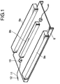
- Fig. 1 is a perspective view of the back surface side, i.e., the opposite side to the light receiving surface, to show an example of the solar battery module according to the present invention
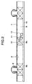
- Fig. 2 is a cross-sectional view to show the installed and secured state of the solar battery module
- Fig. 3 is a partly enlarged, cross-sectional view of part A of Fig. 2.
- the solar battery panel 1 includes the photovoltaic element 2 resin-sealed with the translucent resin 3 and has the translucent resin film 4 on the light receiving surface and the metal reinforcing sheet 5 on the back surface side, which are stacked by bonding.
- an example of the method for bonding these in stack is a method for stacking the sheet translucent resin 3, photovoltaic element 2, sheet translucent resin 3, and translucent resin film 4 in order on the metal reinforcing sheet 5 and fusing the sheet translucent resin sheets 3 with degassing under pressure.
- the solar battery module of the present embodiment will be described with reference to Fig. 1 and Fig. 2.
- the solar battery panel 1 fabricated as described above is bent by folding to form flanges 6.
- the spacer members 9a, 9b are fixed to the metal reinforcing sheet 5 of the solar battery panel 1 by adhesive, screws, nails, or the like, for forming a draft layer 8 between the solar battery panel 1 and the roof substrate material on which the solar battery panel 1 is to be installed.
- the spacer members 9a are fixed to the roof substrate material 18 of sheathing roof board and the like by unillustrated nails as shown in Fig. 2, thereby installing and securing the solar battery module with forming the space 8.
- Fig. 7 is an example in which the roofing material of the present invention is applied to a heating system for home.
- Arrows indicate the flow of air.
- the air taken through the eaves 21 flows through the draft layer 8 to be heated by thermal conduction from the solar battery panels 1 and the heated air is taken into the room 20 via the ridge 22 to be used for heating.
- a heat accumulating device may be provided below the floor.
- a fan F is provided midway of the air flow passage.
- the air taken through the eaves 21 is discharged from exhaust port 23 to the outside to enhance the heat insulating function of the roof, thereby keeping the environment in the room 20 comfortable.
- the solar battery panel 1 is used together with an inverter I, thus composing a solar electric power generation system.
- the power converted by the inverter I is supplied to the fan F and to the other loads 24 in the home.
- the invention obviates the need for the cumbersome works for installing and securing the spacer members at the accurate positions on the roof substrate material in correspondence to the installing and securing sites of solar battery module as conducted before, thus greatly improving workability at the construction site. Consequently, it can decrease the construction period and also decrease the construction costs.
- the structural strength of solar battery module can be increased in portions near the places where the junction boxes are mounted.
- a solar battery panel suitably used as a combination roofing material and solar battery module is the one as described above wherein the translucent resin film 4 is provided on the light receiving surface, the photovoltaic element 2 is resin-sealed by the translucent resin 3, and the panel, together with the metal reinforcing sheet 5, can be bent by folding.
- the photovoltaic element includes monocrystal silicon photovoltaic elements and non-monocrystal photovoltaic elements, specifically, polycrystal silicon photovoltaic elements, amorphous silicon photovoltaic elements, copper indium selenide photovoltaic elements, compound semiconductor photovoltaic elements, and so on.
- the photovoltaic element 2 is selected from the non-monocrystal photovoltaic elements.
- a more preferred photovoltaic element is a photovoltaic element having flexibility and an especially preferred photovoltaic element is an amorphous silicon photovoltaic element formed on a stainless steel substrate.
- the photovoltaic element having flexibility, even if a worker steps on the solar battery module during the installation work or the like on the roof, the photovoltaic element will be prevented from being broken, and thus, it is very suitable for the combination roofing material and solar battery module. Since amorphous silicon shows less reduction in conversion efficiency due to heat than single silicon crystals, it is suitably applicable to the combination roofing material and solar battery. In addition, amorphous silicon can be expected to show the effect to recover optical degradation by annealing.
- the translucent resin is used for sealing or bonding of the photovoltaic element 2.
- Specific examples of the translucent resin include ethylene-vinyl acetate copolymer (EVA), polyvinyl butyral, and silicone resin, but it is not limited to these.
- the translucent resin film is preferably one having high weatherability, and a suitable example is a fluorocarbon resin film.
- a preferred film is one having an elongation factor of film not less than 250 %. If below 250 %, there is a possibility that cracks appear during folding of the solar battery panel 1.
- a preferred example of the metal reinforcing sheet is one excellent in weatherability, corrosion resistance, and foldability.
- Examples of such reinforcing sheet include galvanized sheet iron, steel sheets coated with a weather-resistant substance such as fluorocarbon resin or vinyl chloride, stainless steel sheets, and so on.
- the spacer members 9a, 9b are members for forming the draft layer 8. They are required to have the ability of sufficiently reinforcing the structural strength of solar battery panel 1 and to have a sufficient height for protecting the junction boxes 10. Provision of the spacer member 9b prevents the panel from being deformed when stress is imparted on the central portion of panel. This improves workability during installation of the panel on the roof.
- the material for the spacer members is preferably one having the heat resistance to the temperatures of about 80°C, considering that the solar battery panel 1 is heated up to the temperatures of about 80°C, and good processability, high corrosion resistance, and so on.
- Examples of the material include metals, timber, and resins having such heat resistance.
- the spacer members may be formed in any shape as long as they can exhibit the aforementioned functions.
- they may be of a rod shape, a block shape of a rectangular parallelepiped or the like, or may be elongate members a cross section of which is a shape of H or I.
- a plurality of spacer members 9b may be provided in the central portion, but they must be installed so as not to impede ventilation of air in the draft layer 8. Therefore, a spacer member is preferably positioned in a rod shape on a straight line connecting the two terminal boxes 10, as shown in Fig. 1.
- the spacer member 9b is formed preferably in a shape that can house at least one of junction boxes 10 and electric output lines 11. It is also permissible to properly bend the reinforcing sheet 5 by folding into a shape also serving as spacer members.
- the spacer member may be provided with electric output line engaging portions that can be engaged with the electric output lines.
- the solar battery module of the present example is characterized in that the junction boxes 10 provided on the back surface side are housed inside the spacer member 9c as shown in Fig. 4, and it is fabricated in the same manner as the aforementioned embodiment except for the points stated specifically herein.
- the photovoltaic element 2 was an amorphous silicon photovoltaic element having a stainless steel substrate 125 ⁇ m thick
- the translucent resin film 4 was an unoriented type fluorocarbon resin film ("TEFZEL” available from du Pont) 50 ⁇ m thick
- the translucent resin 3 was EVA (which was formed in the thickness of 900 ⁇ m on each of the front and back surfaces of the photovoltaic element 2)
- the metal reinforcing sheet 5 was a galvanized iron sheet ("Taima color GL” available from Daido Kohan Kabushiki Kaisha) 0.4 mm thick. They were stacked in order and EVA was fused at 150°C with degassing under pressure to bond them in stack, thus fabricating the solar battery panel 1.
- the metal reinforcing sheet 5 was preliminarily perforated in the portions corresponding to the terminal outlet positions, through which the outlet terminals of the positive pole and negative pole were taken out.
- the junction boxes 10 of polycarbonate were provided for protection and waterproof in the terminal outlet portions and the electric output lines 11 with the connector 12 at the tip were guided out of the junction boxes.
- the flange portions 6 were formed by such folding that the inner radius of curvature became 2 mm, by use of a normal "folding machine for steel sheet".
- the spacer members 9a were made of a timber material and the spacer member 9c was made by bending galvanized sheet iron 1.2 mm thick in a U-shaped cross section. This spacer member 9c was mounted so as to receive the junction boxes 10 inside thereof.
- the spacer member 9c was bonded and fixed to the metal reinforcing sheet 5 with a silicone based adhesive.
- junction boxes 10 are housed inside of the spacer member 9c, even if the load is exerted on the portions where the junction boxes 10 exist, curvature of solar battery module will be small, which can prevent breakage of junction boxes 10, dissociation of bonding at the bonding interface between the junction boxes 10 and the metal reinforcing sheet 5, and so on.
- the solar battery module of the present example is characterized in that the spacer member has electric output line engaging portions.
- the solar battery module of the present example was fabricated in the same manner as in Example 1 except for the points described specifically herein.
- Fig. 5 is a perspective view of the back surface side of the solar battery module of the present example.
- the spacer member 9d of the solar battery module of the present embodiment has engaging portions 9e with which the electric output lines 11 can be engaged.
- the electric output lines 11 are engaged with the spacer member 9d, it can avoid a problem that the electric output lines 11 are suspended to catch another article, for example, during carriage of the solar battery module at the installing and securing site, it can demonstrate very good handlability, and it can improve workability extremely.
- the solar battery module of Fig. 6 is an example in which the reinforcing sheet 5 is formed in such integral structure as to also serve as the spacer members without use of separate members as spacer members.
- the reinforcing sheet 5 is bent by folding to form the spacer members 9a and flange portions 6.
- Each spacer member 9a is provided with through holes 18 through which nails are inserted for fixing the module body to the roof substrate material.
- the solar battery module of the present example can be fabricated in the same manner as in Example 1 except for the above point.
- the spacer members 9a also serving as the portions for fixing the module body are formed integrally, reliability can be enhanced of fixation of the module onto the roof substrate material.
- a solar battery module is constructed in such a way that a photovoltaic element is fixed on a reinforcing sheet, a plurality of junction boxes for drawing power out of the photovoltaic element to the outside are provided on an anti-light-receiving-surface side of the reinforcing sheet, first spacer members having a height higher than a height of the junction boxes are placed along two opposite sides of the reinforcing sheet, and a second spacer member is placed between the plurality of junction boxes.
- the first spacer members are fixed on a roof substrate material, a space defined between the roofing material and the roof substrate material is open to the outside air, and the space is in communication with the inside of a house at the ridge.
- the above structure simplifies works for securing combination solar battery and roofing materials with forming a draft layer onto the roof.
- the above structure prevents the panel from being deformed and prevents the junction boxes from being broken.
Landscapes
- Engineering & Computer Science (AREA)
- Architecture (AREA)
- Civil Engineering (AREA)
- Structural Engineering (AREA)
- Roof Covering Using Slabs Or Stiff Sheets (AREA)
- Photovoltaic Devices (AREA)
Abstract
Description
Claims (19)
- A solar battery module wherein a photovoltaic element is fixed on a reinforcing sheet, a plurality of junction boxes for drawing power out of said photovoltaic element to the outside are provided on an anti-light-receiving-surface side of the reinforcing sheet, first spacer members having a height higher than a height of the junction boxes are placed along two opposite sides of the reinforcing sheet, and a second spacer member is placed between said plurality of junction boxes.
- A solar battery module according to Claim 1, wherein said junction boxes are placed in a space defined by said second spacer member.
- A solar battery module according to Claim 1, wherein an output line is connected to each said junction box and said output line has an engaging portion for engaging the output line with a part of said second spacer member.
- A solar battery module according to Claim 1, wherein said first spacer members are formed by folding of said reinforcing sheet.
- A roofing material wherein a photovoltaic element is fixed on a reinforcing sheet, a plurality of junction boxes for drawing power out of said photovoltaic element to the outside are provided on an anti-light-receiving-surface side of the reinforcing sheet, first spacer members having a height higher than a height of the junction boxes are placed along two opposite sides of the reinforcing sheet, and a second spacer member is placed between said plurality of junction boxes.
- A roofing material according to Claim 5, wherein said junction boxes are placed in a space defined by said second spacer member.
- A roofing material according to Claim 5, wherein an output line is connected to each said junction box and said output line has an engaging portion for engaging the output line with a part of said second spacer member.
- A roofing material according to Claim 5, wherein said first spacer members are formed by folding of said reinforcing sheet.
- A roofing material wherein a photovoltaic element is fixed on a reinforcing sheet, two opposite sides of said reinforcing sheet are bent, a plurality of junction boxes for drawing power out of said photovoltaic element to the outside are provided on an anti-light-receiving-surface side of the reinforcing sheet, first spacer members having a height higher than a height of the junction boxes are placed along the two bent sides of said reinforcing sheet, and a second spacer member is placed between said plurality of junction boxes, a plurality of adjacent roofing materials being arranged in such a manner that said first spacer members of the respective roofing materials are fixed adjacent to each other on a roof substrate material and that a batten is placed so as to cover the bent portions of said adjacent reinforcing sheets.
- A mounting method of a roofing material wherein a photovoltaic element is fixed on a reinforcing sheet, a plurality of junction boxes for drawing power out of said photovoltaic element to the outside are provided on an anti-light-receiving-surface side of the reinforcing sheet, first spacer members having a height higher than a height of the junction boxes are placed along two opposite sides of the reinforcing sheet, and a second spacer member is placed between said plurality of junction boxes;
wherein said first spacer members of said roofing material are fixed on a roof substrate material. - A mounting method of roofing material according to Claim 10, wherein the two opposite sides of said reinforcing sheet are bent, said first spacer members are provided along the two bent sides, and said first spacer members project out from edge faces of said reinforcing sheet, said first spacer members being fixed on the roof substrate material in portions thus projecting out.
- A mounting method of roofing material according to Claim 10, wherein a plurality of roofing materials are fixed with non-bent sides thereof being in contact, said mounting method comprising a step of electrically connecting said roofing materials with each other.
- A mounting method of roofing material according to Claim 10, wherein said roofing material is placed so that the outside air is guided into a space defined between said roofing material and said roof substrate material and that the air having passed through the space is introduced into the inside of a house.
- A mounting method of a roofing material wherein a photovoltaic element is fixed on a reinforcing sheet, two opposite sides of said reinforcing sheet are bent, a plurality of junction boxes for drawing power out of said photovoltaic element to the outside are provided on an anti-light-receiving-surface side of the reinforcing sheet, first spacer members having a height higher than a height of the junction boxes are placed along the two bent sides of said reinforcing sheet, and a second spacer member is placed between said plurality of junction boxes;
wherein said first spacer members of a plurality of adjacent roofing materials are fixed adjacent to each other on a roof substrate material and a batten is placed so as to cover bent portions of said adjacent reinforcing sheets. - A fabrication process of roofing material comprising a step of securing to a reinforcing sheet of a solar battery module, said solar battery module having a photovoltaic element fixed on the reinforcing sheet and having junction boxes for drawing power out of said photovoltaic element to the outside on an anti-light-receiving-surface side of the reinforcing sheet, first spacer members having a height higher than a height of said junction boxes along two opposite sides of said reinforcing sheet, and a step of placing a second spacer member between said plurality of junction boxes.
- A fabrication process of roofing material according to Claim 15, further comprising a step of folding said reinforcing sheet.
- A roof comprising a roofing material wherein a photovoltaic element is fixed on a reinforcing sheet, a plurality of junction boxes for drawing power out of said photovoltaic element to the outside are provided on an anti-light-receiving-surface side of the reinforcing sheet, first spacer members having a height higher than a height of the junction boxes are placed along two opposite sides of the reinforcing sheet, and a second spacer member is placed between said plurality of junction boxes;
wherein said first spacer members of the roofing material are fixed on a roof substrate material and wherein a space defined between said roofing material and said roof substrate material is open to the outside air at the eaves and is in communication with the inside of a house at the ridge. - A roof according to Claim 17, comprising a path for discharging the air taken in at said eaves to the outside.
- A solar electric power generation system comprising:a solar battery module wherein a photovoltaic element is fixed on a reinforcing sheet, a plurality of junction boxes for drawing power out of said photovoltaic element to the outside are provided on an anti-light-receiving-surface side of the reinforcing sheet, first spacer members having a height higher than a height of the junction boxes are placed along two opposite sides of the reinforcing sheet, and a second spacer member is placed between said plurality of junction boxes; andan inverter electrically connected to said solar battery module.
Applications Claiming Priority (2)
| Application Number | Priority Date | Filing Date | Title |
|---|---|---|---|
| JP8224672A JPH1054118A (en) | 1996-08-08 | 1996-08-08 | Solar cell module |
| JP224672/96 | 1996-08-08 |
Publications (2)
| Publication Number | Publication Date |
|---|---|
| EP0824273A2 true EP0824273A2 (en) | 1998-02-18 |
| EP0824273A3 EP0824273A3 (en) | 1999-05-26 |
Family
ID=16817414
Family Applications (1)
| Application Number | Title | Priority Date | Filing Date |
|---|---|---|---|
| EP97113707A Withdrawn EP0824273A3 (en) | 1996-08-08 | 1997-08-07 | Solar battery module and roofing material incorporating it |
Country Status (6)
| Country | Link |
|---|---|
| US (1) | US6498289B1 (en) |
| EP (1) | EP0824273A3 (en) |
| JP (1) | JPH1054118A (en) |
| KR (1) | KR100251069B1 (en) |
| CN (1) | CN1082597C (en) |
| AU (1) | AU736617B2 (en) |
Cited By (50)
| Publication number | Priority date | Publication date | Assignee | Title |
|---|---|---|---|---|
| EP0978884A3 (en) * | 1998-06-12 | 2000-03-22 | Canon Kabushiki Kaisha | Solar cell module, solar cell module string, solar cell system, and method for supervising said solar cell module or solar cell module string |
| EP0962989A3 (en) * | 1998-05-20 | 2003-07-30 | Canon Kabushiki Kaisha | Photovoltaic power generating structure |
| DE20310760U1 (en) * | 2003-07-11 | 2004-11-18 | SCHÜCO International KG | mounting system |
| EP2012365A1 (en) * | 2007-07-06 | 2009-01-07 | Terreal | Device for integrating solar panels on a roof, especially for photovoltaic panels |
| WO2009074335A1 (en) | 2007-12-13 | 2009-06-18 | Yamaichi Electronics Deutschland Gmbh | Junction box, system, method, and use |
| US7605498B2 (en) | 2007-10-15 | 2009-10-20 | Ampt, Llc | Systems for highly efficient solar power conversion |
| US7919953B2 (en) | 2007-10-23 | 2011-04-05 | Ampt, Llc | Solar power capacitor alternative switch circuitry system for enhanced capacitor life |
| US9397497B2 (en) | 2013-03-15 | 2016-07-19 | Ampt, Llc | High efficiency interleaved solar power supply system |
| US9442504B2 (en) | 2009-04-17 | 2016-09-13 | Ampt, Llc | Methods and apparatus for adaptive operation of solar power systems |
| US9466737B2 (en) | 2009-10-19 | 2016-10-11 | Ampt, Llc | Solar panel string converter topology |
| US10007288B2 (en) | 2012-03-05 | 2018-06-26 | Solaredge Technologies Ltd. | Direct current link circuit |
| US10097007B2 (en) | 2006-12-06 | 2018-10-09 | Solaredge Technologies Ltd. | Method for distributed power harvesting using DC power sources |
| US10230310B2 (en) | 2016-04-05 | 2019-03-12 | Solaredge Technologies Ltd | Safety switch for photovoltaic systems |
| US10230245B2 (en) | 2006-12-06 | 2019-03-12 | Solaredge Technologies Ltd | Battery power delivery module |
| US10381977B2 (en) | 2012-01-30 | 2019-08-13 | Solaredge Technologies Ltd | Photovoltaic panel circuitry |
| US10396662B2 (en) | 2011-09-12 | 2019-08-27 | Solaredge Technologies Ltd | Direct current link circuit |
| US10447150B2 (en) | 2006-12-06 | 2019-10-15 | Solaredge Technologies Ltd. | Distributed power harvesting systems using DC power sources |
| US10461687B2 (en) | 2008-12-04 | 2019-10-29 | Solaredge Technologies Ltd. | Testing of a photovoltaic panel |
| US10468878B2 (en) | 2008-05-05 | 2019-11-05 | Solaredge Technologies Ltd. | Direct current power combiner |
| US10516336B2 (en) | 2007-08-06 | 2019-12-24 | Solaredge Technologies Ltd. | Digital average input current control in power converter |
| US10608553B2 (en) | 2012-01-30 | 2020-03-31 | Solaredge Technologies Ltd. | Maximizing power in a photovoltaic distributed power system |
| US10637393B2 (en) | 2006-12-06 | 2020-04-28 | Solaredge Technologies Ltd. | Distributed power harvesting systems using DC power sources |
| US10644589B2 (en) | 2007-12-05 | 2020-05-05 | Solaredge Technologies Ltd. | Parallel connected inverters |
| US10666125B2 (en) | 2011-01-12 | 2020-05-26 | Solaredge Technologies Ltd. | Serially connected inverters |
| US10673222B2 (en) | 2010-11-09 | 2020-06-02 | Solaredge Technologies Ltd. | Arc detection and prevention in a power generation system |
| US10673229B2 (en) | 2010-11-09 | 2020-06-02 | Solaredge Technologies Ltd. | Arc detection and prevention in a power generation system |
| US10778025B2 (en) | 2013-03-14 | 2020-09-15 | Solaredge Technologies Ltd. | Method and apparatus for storing and depleting energy |
| US10931119B2 (en) | 2012-01-11 | 2021-02-23 | Solaredge Technologies Ltd. | Photovoltaic module |
| US10931228B2 (en) | 2010-11-09 | 2021-02-23 | Solaredge Technologies Ftd. | Arc detection and prevention in a power generation system |
| US10969412B2 (en) | 2009-05-26 | 2021-04-06 | Solaredge Technologies Ltd. | Theft detection and prevention in a power generation system |
| US10992238B2 (en) | 2012-01-30 | 2021-04-27 | Solaredge Technologies Ltd. | Maximizing power in a photovoltaic distributed power system |
| US11018623B2 (en) | 2016-04-05 | 2021-05-25 | Solaredge Technologies Ltd. | Safety switch for photovoltaic systems |
| US11031861B2 (en) | 2006-12-06 | 2021-06-08 | Solaredge Technologies Ltd. | System and method for protection during inverter shutdown in distributed power installations |
| US11177663B2 (en) | 2016-04-05 | 2021-11-16 | Solaredge Technologies Ltd. | Chain of power devices |
| US11264947B2 (en) | 2007-12-05 | 2022-03-01 | Solaredge Technologies Ltd. | Testing of a photovoltaic panel |
| US11309832B2 (en) | 2006-12-06 | 2022-04-19 | Solaredge Technologies Ltd. | Distributed power harvesting systems using DC power sources |
| US11569659B2 (en) | 2006-12-06 | 2023-01-31 | Solaredge Technologies Ltd. | Distributed power harvesting systems using DC power sources |
| US11569660B2 (en) | 2006-12-06 | 2023-01-31 | Solaredge Technologies Ltd. | Distributed power harvesting systems using DC power sources |
| US11579235B2 (en) | 2006-12-06 | 2023-02-14 | Solaredge Technologies Ltd. | Safety mechanisms, wake up and shutdown methods in distributed power installations |
| US11598652B2 (en) | 2006-12-06 | 2023-03-07 | Solaredge Technologies Ltd. | Monitoring of distributed power harvesting systems using DC power sources |
| US11687112B2 (en) | 2006-12-06 | 2023-06-27 | Solaredge Technologies Ltd. | Distributed power harvesting systems using DC power sources |
| US11728768B2 (en) | 2006-12-06 | 2023-08-15 | Solaredge Technologies Ltd. | Pairing of components in a direct current distributed power generation system |
| US11735910B2 (en) | 2006-12-06 | 2023-08-22 | Solaredge Technologies Ltd. | Distributed power system using direct current power sources |
| US11855231B2 (en) | 2006-12-06 | 2023-12-26 | Solaredge Technologies Ltd. | Distributed power harvesting systems using DC power sources |
| US11881814B2 (en) | 2005-12-05 | 2024-01-23 | Solaredge Technologies Ltd. | Testing of a photovoltaic panel |
| US11888387B2 (en) | 2006-12-06 | 2024-01-30 | Solaredge Technologies Ltd. | Safety mechanisms, wake up and shutdown methods in distributed power installations |
| US12027849B2 (en) | 2006-12-06 | 2024-07-02 | Solaredge Technologies Ltd. | Distributed power system using direct current power sources |
| US12057807B2 (en) | 2016-04-05 | 2024-08-06 | Solaredge Technologies Ltd. | Chain of power devices |
| US12418177B2 (en) | 2009-10-24 | 2025-09-16 | Solaredge Technologies Ltd. | Distributed power system using direct current power sources |
| US12633754B2 (en) | 2012-01-30 | 2026-05-19 | Solaredge Technologies Ltd. | Maximizing power in a photovoltaic distributed power system |
Families Citing this family (38)
| Publication number | Priority date | Publication date | Assignee | Title |
|---|---|---|---|---|
| US5746839A (en) * | 1996-04-08 | 1998-05-05 | Powerlight Corporation | Lightweight, self-ballasting photovoltaic roofing assembly |
| EP1270842B1 (en) | 2000-03-28 | 2012-05-02 | Kaneka Corporation | Solar cell module and roof equipped with power generating function using it |
| JP2002141539A (en) * | 2000-10-30 | 2002-05-17 | Canon Inc | Solar cell module, method of manufacturing the same, and power generation device |
| US6883290B2 (en) * | 2002-02-20 | 2005-04-26 | Powerlight Corporation | Shingle system and method |
| US20030154667A1 (en) * | 2002-02-20 | 2003-08-21 | Dinwoodie Thomas L. | Shingle system |
| US7178295B2 (en) | 2002-02-20 | 2007-02-20 | Powerlight Corporation | Shingle assembly |
| US6928775B2 (en) * | 2002-08-16 | 2005-08-16 | Mark P. Banister | Multi-use electric tile modules |
| US7578102B2 (en) * | 2002-08-16 | 2009-08-25 | Mark Banister | Electric tile modules |
| AU2004267844C1 (en) * | 2003-08-20 | 2009-01-08 | Totalenergies Onetech | PV wind performance enhancing methods and apparatus |
| CA2562703A1 (en) * | 2004-04-13 | 2005-10-27 | Cedar Valley Manufacturing, Inc. | Shingled siding unit |
| AU2005250970A1 (en) * | 2004-06-04 | 2005-12-15 | Ats Automation Tooling Systems Inc. | Method for construction of rigid photovoltaic modules |
| US20080156365A1 (en) * | 2006-10-25 | 2008-07-03 | Scholz Jeremy H | Edge mountable electrical connection assembly |
| FR2922365B1 (en) * | 2007-10-16 | 2009-12-18 | Avancis Gmbh & Co Kg | IMPROVEMENTS TO ELEMENTS CAPABLE OF COLLECTING LIGHT. |
| EP2253773B1 (en) | 2008-02-28 | 2015-02-18 | Kyocera Corporation | Photovoltaic power generating system |
| US8316593B2 (en) * | 2009-03-18 | 2012-11-27 | Garland Industries, Inc. | Solar roofing system |
| CN101509306B (en) * | 2009-03-20 | 2011-02-02 | 大连理工大学 | Photoelectric integration construction material based on dye sensitization solar energy cell |
| WO2010117018A1 (en) * | 2009-04-08 | 2010-10-14 | シャープ株式会社 | Solar cell module, pedestal for solar cells, and photovoltaic power generation system |
| JP5582936B2 (en) * | 2009-10-19 | 2014-09-03 | 京セラ株式会社 | Solar cell module |
| US8196369B2 (en) * | 2010-01-28 | 2012-06-12 | Frank Pao | Building integrated thermal electric hybrid roofing system |
| CN101876195A (en) * | 2010-03-24 | 2010-11-03 | 浙江省建筑科学设计研究院有限公司 | Photovoltaic array waste heat water-cooled recovery system integrated with building roof |
| JP5263795B2 (en) * | 2010-03-25 | 2013-08-14 | シャープ株式会社 | Solar cell module mounting structure |
| CN101958351B (en) * | 2010-04-20 | 2013-05-15 | 常州天合光能有限公司 | Solar cell module with multiple junction boxes |
| EP2390924A1 (en) * | 2010-05-26 | 2011-11-30 | Thesan S.p.A. | Building roof with rows of curved tiles alternating with strip-shaped solar modules, and sheet-metal panel for making said roof |
| JP5570362B2 (en) * | 2010-09-22 | 2014-08-13 | シャープ株式会社 | Solar cell module |
| US8365500B2 (en) | 2010-12-22 | 2013-02-05 | Frank Pao | Optimized building integrated hybrid roofing system |
| US8201382B1 (en) | 2010-12-22 | 2012-06-19 | Frank Pao | Building integrated thermal electric hybrid roofing system |
| US8887453B2 (en) * | 2011-05-16 | 2014-11-18 | Hanergy Holding Group Ltd | Supporting structures for building integrable photovoltaic modules |
| CN102361041A (en) * | 2011-10-10 | 2012-02-22 | 常州市东君光能科技发展有限公司 | Solar cell subassembly |
| CN103165706B (en) * | 2011-12-08 | 2015-10-21 | 杜邦公司 | Film solar battery module |
| US8898968B2 (en) * | 2012-07-09 | 2014-12-02 | Alexander Freimark Keller | Solar power unit and system |
| KR101256648B1 (en) | 2013-01-10 | 2013-04-23 | 영남대학교 산학협력단 | Panel equipped with solar cell module and outer of building thereof |
| WO2014155910A1 (en) * | 2013-03-29 | 2014-10-02 | 三洋電機株式会社 | Solar cell system |
| JP6501762B2 (en) * | 2013-06-03 | 2019-04-17 | ブルースコープ・スティール・リミテッドBluescope Steel Limited | Solar roof panel |
| CA2924385A1 (en) * | 2013-10-17 | 2015-04-23 | Designergy Sa | Building construction surface element and building construction / building construction surface arrangement and method to manufacture same |
| JP5629399B2 (en) * | 2014-03-28 | 2014-11-19 | シャープ株式会社 | Solar cell module and solar power generation system |
| JP5612230B2 (en) * | 2014-03-28 | 2014-10-22 | シャープ株式会社 | Solar cell module |
| US20190288637A1 (en) * | 2018-03-15 | 2019-09-19 | Better Natural, LLC | Method of integrating solar panels in the roof substrate structure |
| CN110699621A (en) * | 2019-10-14 | 2020-01-17 | 青海金功新能源技术有限公司 | A kind of solar photovoltaic/photothermal support system steel member galvanizing method |
Family Cites Families (18)
| Publication number | Priority date | Publication date | Assignee | Title |
|---|---|---|---|---|
| SE7604250L (en) * | 1975-05-06 | 1976-11-07 | Svenska Flaektfabriken Ab | METHOD AND DEVICE FOR THE EXTRACTION OF HEAT ENERGY |
| IT1095999B (en) * | 1978-05-18 | 1985-08-17 | Nardini Gian Vieri | SOLAR CAPTORS COMPOSED WITH BITUMATED FELTS, BITUMATED CARTONFELTS OR SHEATHS |
| US4315163A (en) * | 1980-09-16 | 1982-02-09 | Frank Bienville | Multipower electrical system for supplying electrical energy to a house or the like |
| US4341607A (en) * | 1980-12-08 | 1982-07-27 | E:F Technology, Inc. | Solar power system requiring no active control device |
| JPS6040778B2 (en) * | 1980-12-10 | 1985-09-12 | ミサワホ−ム株式会社 | Air duct for solar heat collection roof equipment |
| US4636577A (en) * | 1983-08-29 | 1987-01-13 | Thomas & Betts Corporation | Solar panel module and support therefor |
| CN85101326A (en) | 1985-04-01 | 1987-01-10 | 夏普公司 | Junction box for solar cell module |
| CN85101373B (en) | 1985-04-01 | 1988-12-07 | 夏普公司 | solar cell device |
| US4830038A (en) * | 1988-01-20 | 1989-05-16 | Atlantic Richfield Company | Photovoltaic module |
| GB8902662D0 (en) | 1989-02-07 | 1989-03-30 | Ridett Alan H | Improvements in or relating to buildings |
| US5092939A (en) * | 1990-11-30 | 1992-03-03 | United Solar Systems Corporation | Photovoltaic roof and method of making same |
| JPH0688645A (en) * | 1991-05-24 | 1994-03-29 | Takashi Takahashi | Heat concentrating bag, its supporting method, and roof-installed solar heat concentrator using said bag |
| CH684202A5 (en) | 1991-07-11 | 1994-07-29 | Plaston Ag Kunststoffwerk Hans | Roof covering and structural element with solar cells |
| JP2974513B2 (en) * | 1992-09-03 | 1999-11-10 | キヤノン株式会社 | Roof material integrated solar cell module |
| US5480494A (en) | 1993-05-18 | 1996-01-02 | Canon Kabushiki Kaisha | Solar cell module and installation method thereof |
| JP3001785B2 (en) * | 1993-11-30 | 2000-01-24 | キヤノン株式会社 | Solar cell module, roofing material, air distribution device, roofing material construction method, and roofing material manufacturing method |
| US5589006A (en) * | 1993-11-30 | 1996-12-31 | Canon Kabushiki Kaisha | Solar battery module and passive solar system using same |
| US5746839A (en) * | 1996-04-08 | 1998-05-05 | Powerlight Corporation | Lightweight, self-ballasting photovoltaic roofing assembly |
-
1996
- 1996-08-08 JP JP8224672A patent/JPH1054118A/en active Pending
-
1997
- 1997-08-01 US US08/904,650 patent/US6498289B1/en not_active Expired - Fee Related
- 1997-08-07 EP EP97113707A patent/EP0824273A3/en not_active Withdrawn
- 1997-08-07 AU AU33206/97A patent/AU736617B2/en not_active Ceased
- 1997-08-07 CN CN97117315A patent/CN1082597C/en not_active Expired - Fee Related
- 1997-08-07 KR KR1019970037734A patent/KR100251069B1/en not_active Expired - Fee Related
Cited By (137)
| Publication number | Priority date | Publication date | Assignee | Title |
|---|---|---|---|---|
| EP0962989A3 (en) * | 1998-05-20 | 2003-07-30 | Canon Kabushiki Kaisha | Photovoltaic power generating structure |
| US6800801B2 (en) | 1998-05-20 | 2004-10-05 | Canon Kabushiki Kaisha | Photovoltaic power generating structure |
| EP0978884A3 (en) * | 1998-06-12 | 2000-03-22 | Canon Kabushiki Kaisha | Solar cell module, solar cell module string, solar cell system, and method for supervising said solar cell module or solar cell module string |
| DE20310760U1 (en) * | 2003-07-11 | 2004-11-18 | SCHÜCO International KG | mounting system |
| US11881814B2 (en) | 2005-12-05 | 2024-01-23 | Solaredge Technologies Ltd. | Testing of a photovoltaic panel |
| US10097007B2 (en) | 2006-12-06 | 2018-10-09 | Solaredge Technologies Ltd. | Method for distributed power harvesting using DC power sources |
| US12276997B2 (en) | 2006-12-06 | 2025-04-15 | Solaredge Technologies Ltd. | Distributed power harvesting systems using DC power sources |
| US11682918B2 (en) | 2006-12-06 | 2023-06-20 | Solaredge Technologies Ltd. | Battery power delivery module |
| US11476799B2 (en) | 2006-12-06 | 2022-10-18 | Solaredge Technologies Ltd. | Distributed power harvesting systems using DC power sources |
| US11569659B2 (en) | 2006-12-06 | 2023-01-31 | Solaredge Technologies Ltd. | Distributed power harvesting systems using DC power sources |
| US11183922B2 (en) | 2006-12-06 | 2021-11-23 | Solaredge Technologies Ltd. | Distributed power harvesting systems using DC power sources |
| US11569660B2 (en) | 2006-12-06 | 2023-01-31 | Solaredge Technologies Ltd. | Distributed power harvesting systems using DC power sources |
| US11687112B2 (en) | 2006-12-06 | 2023-06-27 | Solaredge Technologies Ltd. | Distributed power harvesting systems using DC power sources |
| US11575261B2 (en) | 2006-12-06 | 2023-02-07 | Solaredge Technologies Ltd. | Distributed power harvesting systems using DC power sources |
| US11575260B2 (en) | 2006-12-06 | 2023-02-07 | Solaredge Technologies Ltd. | Distributed power harvesting systems using DC power sources |
| US11579235B2 (en) | 2006-12-06 | 2023-02-14 | Solaredge Technologies Ltd. | Safety mechanisms, wake up and shutdown methods in distributed power installations |
| US11309832B2 (en) | 2006-12-06 | 2022-04-19 | Solaredge Technologies Ltd. | Distributed power harvesting systems using DC power sources |
| US12316274B2 (en) | 2006-12-06 | 2025-05-27 | Solaredge Technologies Ltd. | Pairing of components in a direct current distributed power generation system |
| US12032080B2 (en) | 2006-12-06 | 2024-07-09 | Solaredge Technologies Ltd. | Safety mechanisms, wake up and shutdown methods in distributed power installations |
| US12281919B2 (en) | 2006-12-06 | 2025-04-22 | Solaredge Technologies Ltd. | Monitoring of distributed power harvesting systems using DC power sources |
| US11063440B2 (en) | 2006-12-06 | 2021-07-13 | Solaredge Technologies Ltd. | Method for distributed power harvesting using DC power sources |
| US11598652B2 (en) | 2006-12-06 | 2023-03-07 | Solaredge Technologies Ltd. | Monitoring of distributed power harvesting systems using DC power sources |
| US12224706B2 (en) | 2006-12-06 | 2025-02-11 | Solaredge Technologies Ltd. | Pairing of components in a direct current distributed power generation system |
| US12107417B2 (en) | 2006-12-06 | 2024-10-01 | Solaredge Technologies Ltd. | Distributed power harvesting systems using DC power sources |
| US11658482B2 (en) | 2006-12-06 | 2023-05-23 | Solaredge Technologies Ltd. | Distributed power harvesting systems using DC power sources |
| US12068599B2 (en) | 2006-12-06 | 2024-08-20 | Solaredge Technologies Ltd. | System and method for protection during inverter shutdown in distributed power installations |
| US12046940B2 (en) | 2006-12-06 | 2024-07-23 | Solaredge Technologies Ltd. | Battery power control |
| US12388492B2 (en) | 2006-12-06 | 2025-08-12 | Solaredge Technologies Ltd. | Safety mechanisms, wake up and shutdown methods in distributed power installations |
| US10230245B2 (en) | 2006-12-06 | 2019-03-12 | Solaredge Technologies Ltd | Battery power delivery module |
| US11594881B2 (en) | 2006-12-06 | 2023-02-28 | Solaredge Technologies Ltd. | Distributed power harvesting systems using DC power sources |
| US12027849B2 (en) | 2006-12-06 | 2024-07-02 | Solaredge Technologies Ltd. | Distributed power system using direct current power sources |
| US12027970B2 (en) | 2006-12-06 | 2024-07-02 | Solaredge Technologies Ltd. | Safety mechanisms, wake up and shutdown methods in distributed power installations |
| US10447150B2 (en) | 2006-12-06 | 2019-10-15 | Solaredge Technologies Ltd. | Distributed power harvesting systems using DC power sources |
| US11043820B2 (en) | 2006-12-06 | 2021-06-22 | Solaredge Technologies Ltd. | Battery power delivery module |
| US11031861B2 (en) | 2006-12-06 | 2021-06-08 | Solaredge Technologies Ltd. | System and method for protection during inverter shutdown in distributed power installations |
| US11728768B2 (en) | 2006-12-06 | 2023-08-15 | Solaredge Technologies Ltd. | Pairing of components in a direct current distributed power generation system |
| US11594882B2 (en) | 2006-12-06 | 2023-02-28 | Solaredge Technologies Ltd. | Distributed power harvesting systems using DC power sources |
| US11594880B2 (en) | 2006-12-06 | 2023-02-28 | Solaredge Technologies Ltd. | Distributed power harvesting systems using DC power sources |
| US10637393B2 (en) | 2006-12-06 | 2020-04-28 | Solaredge Technologies Ltd. | Distributed power harvesting systems using DC power sources |
| US11962243B2 (en) | 2006-12-06 | 2024-04-16 | Solaredge Technologies Ltd. | Method for distributed power harvesting using DC power sources |
| US11961922B2 (en) | 2006-12-06 | 2024-04-16 | Solaredge Technologies Ltd. | Distributed power harvesting systems using DC power sources |
| US11888387B2 (en) | 2006-12-06 | 2024-01-30 | Solaredge Technologies Ltd. | Safety mechanisms, wake up and shutdown methods in distributed power installations |
| US11735910B2 (en) | 2006-12-06 | 2023-08-22 | Solaredge Technologies Ltd. | Distributed power system using direct current power sources |
| US10673253B2 (en) | 2006-12-06 | 2020-06-02 | Solaredge Technologies Ltd. | Battery power delivery module |
| US11855231B2 (en) | 2006-12-06 | 2023-12-26 | Solaredge Technologies Ltd. | Distributed power harvesting systems using DC power sources |
| US8093756B2 (en) | 2007-02-15 | 2012-01-10 | Ampt, Llc | AC power systems for renewable electrical energy |
| EP2012365A1 (en) * | 2007-07-06 | 2009-01-07 | Terreal | Device for integrating solar panels on a roof, especially for photovoltaic panels |
| FR2918397A1 (en) * | 2007-07-06 | 2009-01-09 | Terreal Soc Par Actions Simpli | DEVICE FOR INTEGRATING SOLAR PANEL ON A ROOF, PARTICULARLY FOR PHOTOVOLTAIC SOLAR. |
| US10516336B2 (en) | 2007-08-06 | 2019-12-24 | Solaredge Technologies Ltd. | Digital average input current control in power converter |
| US11594968B2 (en) | 2007-08-06 | 2023-02-28 | Solaredge Technologies Ltd. | Digital average input current control in power converter |
| US8482153B2 (en) | 2007-10-15 | 2013-07-09 | Ampt, Llc | Systems for optimized solar power inversion |
| US7843085B2 (en) | 2007-10-15 | 2010-11-30 | Ampt, Llc | Systems for highly efficient solar power |
| US12003110B2 (en) | 2007-10-15 | 2024-06-04 | Ampt, Llc | Optimized conversion system |
| US10608437B2 (en) | 2007-10-15 | 2020-03-31 | Ampt, Llc | Feedback based photovoltaic conversion systems |
| US12027867B2 (en) | 2007-10-15 | 2024-07-02 | Ampt, Llc | Coordinated converter reactively altering disabling photovoltaic electrical energy power system |
| US12027869B2 (en) | 2007-10-15 | 2024-07-02 | Ampt, Llc | Optimized photovoltaic conversion configuration |
| US10326283B2 (en) | 2007-10-15 | 2019-06-18 | Ampt, Llc | Converter intuitive photovoltaic electrical energy power system |
| US11070063B2 (en) | 2007-10-15 | 2021-07-20 | Ampt, Llc | Method for alternating conversion solar power |
| US9673630B2 (en) | 2007-10-15 | 2017-06-06 | Ampt, Llc | Protected conversion solar power system |
| US11070062B2 (en) | 2007-10-15 | 2021-07-20 | Ampt, Llc | Photovoltaic conversion systems |
| US9438037B2 (en) | 2007-10-15 | 2016-09-06 | Ampt, Llc | Systems for optimized solar power inversion |
| US11289917B1 (en) | 2007-10-15 | 2022-03-29 | Ampt, Llc | Optimized photovoltaic conversion system |
| US8304932B2 (en) | 2007-10-15 | 2012-11-06 | Ampt, Llc | Efficient solar energy power creation systems |
| US8242634B2 (en) | 2007-10-15 | 2012-08-14 | Ampt, Llc | High efficiency remotely controllable solar energy system |
| US8004116B2 (en) | 2007-10-15 | 2011-08-23 | Ampt, Llc | Highly efficient solar power systems |
| US7605498B2 (en) | 2007-10-15 | 2009-10-20 | Ampt, Llc | Systems for highly efficient solar power conversion |
| US10886746B1 (en) | 2007-10-15 | 2021-01-05 | Ampt, Llc | Alternating conversion solar power system |
| US7719140B2 (en) | 2007-10-15 | 2010-05-18 | Ampt, Llc | Systems for boundary controlled solar power conversion |
| US11228182B2 (en) | 2007-10-15 | 2022-01-18 | Ampt, Llc | Converter disabling photovoltaic electrical energy power system |
| US7919953B2 (en) | 2007-10-23 | 2011-04-05 | Ampt, Llc | Solar power capacitor alternative switch circuitry system for enhanced capacitor life |
| US8461811B2 (en) | 2007-10-23 | 2013-06-11 | Ampt, Llc | Power capacitor alternative switch circuitry system for enhanced capacitor life |
| US11264947B2 (en) | 2007-12-05 | 2022-03-01 | Solaredge Technologies Ltd. | Testing of a photovoltaic panel |
| US11183923B2 (en) | 2007-12-05 | 2021-11-23 | Solaredge Technologies Ltd. | Parallel connected inverters |
| US10644589B2 (en) | 2007-12-05 | 2020-05-05 | Solaredge Technologies Ltd. | Parallel connected inverters |
| US11894806B2 (en) | 2007-12-05 | 2024-02-06 | Solaredge Technologies Ltd. | Testing of a photovoltaic panel |
| US12055647B2 (en) | 2007-12-05 | 2024-08-06 | Solaredge Technologies Ltd. | Parallel connected inverters |
| US10693415B2 (en) | 2007-12-05 | 2020-06-23 | Solaredge Technologies Ltd. | Testing of a photovoltaic panel |
| US11693080B2 (en) | 2007-12-05 | 2023-07-04 | Solaredge Technologies Ltd. | Parallel connected inverters |
| US11183969B2 (en) | 2007-12-05 | 2021-11-23 | Solaredge Technologies Ltd. | Testing of a photovoltaic panel |
| WO2009074335A1 (en) | 2007-12-13 | 2009-06-18 | Yamaichi Electronics Deutschland Gmbh | Junction box, system, method, and use |
| US12218498B2 (en) | 2008-05-05 | 2025-02-04 | Solaredge Technologies Ltd. | Direct current power combiner |
| US10468878B2 (en) | 2008-05-05 | 2019-11-05 | Solaredge Technologies Ltd. | Direct current power combiner |
| US11424616B2 (en) | 2008-05-05 | 2022-08-23 | Solaredge Technologies Ltd. | Direct current power combiner |
| US10461687B2 (en) | 2008-12-04 | 2019-10-29 | Solaredge Technologies Ltd. | Testing of a photovoltaic panel |
| US10326282B2 (en) | 2009-04-17 | 2019-06-18 | Ampt, Llc | Safety methods and apparatus for adaptive operation of solar power systems |
| US9442504B2 (en) | 2009-04-17 | 2016-09-13 | Ampt, Llc | Methods and apparatus for adaptive operation of solar power systems |
| US10938219B2 (en) | 2009-04-17 | 2021-03-02 | Ampt, Llc | Dynamic methods and apparatus for adaptive operation of solar power systems |
| US12306215B2 (en) | 2009-05-26 | 2025-05-20 | Solaredge Technologies Ltd. | Theft detection and prevention in a power generation system |
| US10969412B2 (en) | 2009-05-26 | 2021-04-06 | Solaredge Technologies Ltd. | Theft detection and prevention in a power generation system |
| US11867729B2 (en) | 2009-05-26 | 2024-01-09 | Solaredge Technologies Ltd. | Theft detection and prevention in a power generation system |
| US10032939B2 (en) | 2009-10-19 | 2018-07-24 | Ampt, Llc | DC power conversion circuit |
| US9466737B2 (en) | 2009-10-19 | 2016-10-11 | Ampt, Llc | Solar panel string converter topology |
| US11411126B2 (en) | 2009-10-19 | 2022-08-09 | Ampt, Llc | DC power conversion circuit |
| US10714637B2 (en) | 2009-10-19 | 2020-07-14 | Ampt, Llc | DC power conversion circuit |
| US12034087B2 (en) | 2009-10-19 | 2024-07-09 | Ampt, Llc | Solar panel power conversion circuit |
| US12418177B2 (en) | 2009-10-24 | 2025-09-16 | Solaredge Technologies Ltd. | Distributed power system using direct current power sources |
| US11489330B2 (en) | 2010-11-09 | 2022-11-01 | Solaredge Technologies Ltd. | Arc detection and prevention in a power generation system |
| US10673229B2 (en) | 2010-11-09 | 2020-06-02 | Solaredge Technologies Ltd. | Arc detection and prevention in a power generation system |
| US10673222B2 (en) | 2010-11-09 | 2020-06-02 | Solaredge Technologies Ltd. | Arc detection and prevention in a power generation system |
| US12407158B2 (en) | 2010-11-09 | 2025-09-02 | Solaredge Technologies Ltd. | Arc detection and prevention in a power generation system |
| US10931228B2 (en) | 2010-11-09 | 2021-02-23 | Solaredge Technologies Ftd. | Arc detection and prevention in a power generation system |
| US12003215B2 (en) | 2010-11-09 | 2024-06-04 | Solaredge Technologies Ltd. | Arc detection and prevention in a power generation system |
| US11349432B2 (en) | 2010-11-09 | 2022-05-31 | Solaredge Technologies Ltd. | Arc detection and prevention in a power generation system |
| US11070051B2 (en) | 2010-11-09 | 2021-07-20 | Solaredge Technologies Ltd. | Arc detection and prevention in a power generation system |
| US12218505B2 (en) | 2011-01-12 | 2025-02-04 | Solaredge Technologies Ltd. | Serially connected inverters |
| US10666125B2 (en) | 2011-01-12 | 2020-05-26 | Solaredge Technologies Ltd. | Serially connected inverters |
| US11205946B2 (en) | 2011-01-12 | 2021-12-21 | Solaredge Technologies Ltd. | Serially connected inverters |
| US10396662B2 (en) | 2011-09-12 | 2019-08-27 | Solaredge Technologies Ltd | Direct current link circuit |
| US11979037B2 (en) | 2012-01-11 | 2024-05-07 | Solaredge Technologies Ltd. | Photovoltaic module |
| US10931119B2 (en) | 2012-01-11 | 2021-02-23 | Solaredge Technologies Ltd. | Photovoltaic module |
| US12094306B2 (en) | 2012-01-30 | 2024-09-17 | Solaredge Technologies Ltd. | Photovoltaic panel circuitry |
| US11929620B2 (en) | 2012-01-30 | 2024-03-12 | Solaredge Technologies Ltd. | Maximizing power in a photovoltaic distributed power system |
| US11183968B2 (en) | 2012-01-30 | 2021-11-23 | Solaredge Technologies Ltd. | Photovoltaic panel circuitry |
| US10992238B2 (en) | 2012-01-30 | 2021-04-27 | Solaredge Technologies Ltd. | Maximizing power in a photovoltaic distributed power system |
| US12633754B2 (en) | 2012-01-30 | 2026-05-19 | Solaredge Technologies Ltd. | Maximizing power in a photovoltaic distributed power system |
| US11620885B2 (en) | 2012-01-30 | 2023-04-04 | Solaredge Technologies Ltd. | Photovoltaic panel circuitry |
| US10608553B2 (en) | 2012-01-30 | 2020-03-31 | Solaredge Technologies Ltd. | Maximizing power in a photovoltaic distributed power system |
| US10381977B2 (en) | 2012-01-30 | 2019-08-13 | Solaredge Technologies Ltd | Photovoltaic panel circuitry |
| US12191668B2 (en) | 2012-01-30 | 2025-01-07 | Solaredge Technologies Ltd. | Maximizing power in a photovoltaic distributed power system |
| US10007288B2 (en) | 2012-03-05 | 2018-06-26 | Solaredge Technologies Ltd. | Direct current link circuit |
| US10778025B2 (en) | 2013-03-14 | 2020-09-15 | Solaredge Technologies Ltd. | Method and apparatus for storing and depleting energy |
| US12003107B2 (en) | 2013-03-14 | 2024-06-04 | Solaredge Technologies Ltd. | Method and apparatus for storing and depleting energy |
| US12255457B2 (en) | 2013-03-14 | 2025-03-18 | Solaredge Technologies Ltd. | Method and apparatus for storing and depleting energy |
| US10116140B2 (en) | 2013-03-15 | 2018-10-30 | Ampt, Llc | Magnetically coupled solar power supply system |
| US12057514B2 (en) | 2013-03-15 | 2024-08-06 | Ampt, Llc | Converter controlled solar power supply system for battery based loads |
| US12538608B2 (en) | 2013-03-15 | 2026-01-27 | Ampt, Llc | Input configured multiphase low ripple solar energy power system |
| US9397497B2 (en) | 2013-03-15 | 2016-07-19 | Ampt, Llc | High efficiency interleaved solar power supply system |
| US11967653B2 (en) | 2013-03-15 | 2024-04-23 | Ampt, Llc | Phased solar power supply system |
| US11121556B2 (en) | 2013-03-15 | 2021-09-14 | Ampt, Llc | Magnetically coupled solar power supply system for battery based loads |
| US12057807B2 (en) | 2016-04-05 | 2024-08-06 | Solaredge Technologies Ltd. | Chain of power devices |
| US12348182B2 (en) | 2016-04-05 | 2025-07-01 | Solaredge Technologies Ltd. | Safety switch for photovoltaic systems |
| US11177663B2 (en) | 2016-04-05 | 2021-11-16 | Solaredge Technologies Ltd. | Chain of power devices |
| US11018623B2 (en) | 2016-04-05 | 2021-05-25 | Solaredge Technologies Ltd. | Safety switch for photovoltaic systems |
| US11201476B2 (en) | 2016-04-05 | 2021-12-14 | Solaredge Technologies Ltd. | Photovoltaic power device and wiring |
| US11870250B2 (en) | 2016-04-05 | 2024-01-09 | Solaredge Technologies Ltd. | Chain of power devices |
| US12627140B2 (en) | 2016-04-05 | 2026-05-12 | Solaredge Technologies Ltd. | Chain of power devices |
| US10230310B2 (en) | 2016-04-05 | 2019-03-12 | Solaredge Technologies Ltd | Safety switch for photovoltaic systems |
Also Published As
| Publication number | Publication date |
|---|---|
| KR19980018462A (en) | 1998-06-05 |
| CN1173576A (en) | 1998-02-18 |
| AU3320697A (en) | 1998-02-12 |
| EP0824273A3 (en) | 1999-05-26 |
| CN1082597C (en) | 2002-04-10 |
| US6498289B1 (en) | 2002-12-24 |
| AU736617B2 (en) | 2001-08-02 |
| KR100251069B1 (en) | 2000-04-15 |
| JPH1054118A (en) | 1998-02-24 |
Similar Documents
| Publication | Publication Date | Title |
|---|---|---|
| US6498289B1 (en) | Solar battery module and roofing material incorporating it | |
| US6128868A (en) | Combination solar battery and roof member, and mounting method thereof | |
| US6182403B1 (en) | Combination solar battery and roof unit and mounting method thereof | |
| EP0828036B1 (en) | Horizontal-roofing roof and mounting method thereof | |
| JP3792867B2 (en) | Solar cell module, solar cell array, and solar power generation apparatus construction method | |
| EP0858115B1 (en) | Roof member comprising a solar cell and mounting method thereof | |
| US6670541B2 (en) | Solar battery, solar generating apparatus, and building | |
| US6207889B1 (en) | Solar battery modules, installation method thereof, and solar power generator using such modules | |
| AU764896B2 (en) | Mounting method for a combination solar battery and roof unit | |
| US20010034982A1 (en) | Solar cell-bearing roof and method for installing solar cell-bearing roof | |
| JP6603102B2 (en) | Solar array | |
| JP4687067B2 (en) | Solar cell module and power lead wire connection method | |
| JP4326990B2 (en) | Roof material integrated solar cell module | |
| JP2004197560A (en) | Building and air distribution equipment | |
| JPH11173678A (en) | Roof panel, roof unit and unit building provided with photothermal hybrid module, and method of assembling the unit building | |
| JPH11284216A (en) | Photovoltaic element, solar cell module, manufacturing method, construction method and solar power generation system | |
| AU752106B2 (en) | Horizontal-roofing roof and mounting method therof | |
| JP2000196130A (en) | SOLAR CELL MODULE, SOLAR CELL ARRAY AND SOLAR POWER GENERATION DEVICE USING SAME, AND METHOD FOR MANUFACTURING AND INSTALLING SOLAR CELL MODULE | |
| JP2001313406A (en) | Wire support / direction determining member, solar cell module, solar cell array, photovoltaic power generator, and method of installing solar cell module | |
| JPH11324235A (en) | Roof with roofing material and pier, and construction method of roofing material and pier | |
| JP2001345473A (en) | Solar cell module, manufacturing method and construction method of the solar cell module, roof and power generation device using the solar cell module | |
| JP2001313405A (en) | Solar cell module and installation method thereof | |
| JP2001036124A (en) | Building material-integrated solar cell module, manufacturing method thereof, envelope structure using the building material-integrated solar cell module, construction method thereof, and power generation device using the building material-integrated solar cell module |
Legal Events
| Date | Code | Title | Description |
|---|---|---|---|
| PUAI | Public reference made under article 153(3) epc to a published international application that has entered the european phase |
Free format text: ORIGINAL CODE: 0009012 |
|
| AK | Designated contracting states |
Kind code of ref document: A2 Designated state(s): CH DE FR GB IT LI |
|
| AX | Request for extension of the european patent |
Free format text: AL;LT;LV;RO;SI |
|
| PUAL | Search report despatched |
Free format text: ORIGINAL CODE: 0009013 |
|
| AK | Designated contracting states |
Kind code of ref document: A3 Designated state(s): AT BE CH DE DK ES FI FR GB GR IE IT LI LU MC NL PT SE |
|
| AX | Request for extension of the european patent |
Free format text: AL;LT;LV;RO;SI |
|
| 17P | Request for examination filed |
Effective date: 19991103 |
|
| AKX | Designation fees paid |
Free format text: CH DE FR GB IT LI |
|
| 17Q | First examination report despatched |
Effective date: 20071005 |
|
| STAA | Information on the status of an ep patent application or granted ep patent |
Free format text: STATUS: THE APPLICATION HAS BEEN WITHDRAWN |
|
| 18W | Application withdrawn |
Effective date: 20091118 |