EP0828352B1 - Système et méthode pour surveiller le niveau de puissance d'un satellite utilisant le traitement de signaux numériques - Google Patents
Système et méthode pour surveiller le niveau de puissance d'un satellite utilisant le traitement de signaux numériques Download PDFInfo
- Publication number
- EP0828352B1 EP0828352B1 EP97114974A EP97114974A EP0828352B1 EP 0828352 B1 EP0828352 B1 EP 0828352B1 EP 97114974 A EP97114974 A EP 97114974A EP 97114974 A EP97114974 A EP 97114974A EP 0828352 B1 EP0828352 B1 EP 0828352B1
- Authority
- EP
- European Patent Office
- Prior art keywords
- carrier
- power
- carriers
- signals
- digital
- Prior art date
- Legal status (The legal status is an assumption and is not a legal conclusion. Google has not performed a legal analysis and makes no representation as to the accuracy of the status listed.)
- Expired - Lifetime
Links
- 238000000034 method Methods 0.000 title claims description 11
- 238000012544 monitoring process Methods 0.000 title claims description 10
- 238000012545 processing Methods 0.000 title claims description 9
- 239000000969 carrier Substances 0.000 claims description 31
- 238000004891 communication Methods 0.000 claims description 23
- 238000005259 measurement Methods 0.000 description 8
- 238000010586 diagram Methods 0.000 description 5
- 230000001360 synchronised effect Effects 0.000 description 4
- 230000001413 cellular effect Effects 0.000 description 3
- 238000012512 characterization method Methods 0.000 description 2
- 230000035945 sensitivity Effects 0.000 description 2
- 238000012935 Averaging Methods 0.000 description 1
- 230000005540 biological transmission Effects 0.000 description 1
- 230000010267 cellular communication Effects 0.000 description 1
- 239000002131 composite material Substances 0.000 description 1
- 238000005562 fading Methods 0.000 description 1
- 238000000691 measurement method Methods 0.000 description 1
- 238000001556 precipitation Methods 0.000 description 1
- 230000003252 repetitive effect Effects 0.000 description 1
- 238000005070 sampling Methods 0.000 description 1
Images


Classifications
-
- H—ELECTRICITY
- H04—ELECTRIC COMMUNICATION TECHNIQUE
- H04B—TRANSMISSION
- H04B7/00—Radio transmission systems, i.e. using radiation field
- H04B7/14—Relay systems
- H04B7/15—Active relay systems
- H04B7/185—Space-based or airborne stations; Stations for satellite systems
- H04B7/1853—Satellite systems for providing telephony service to a mobile station, i.e. mobile satellite service
- H04B7/18539—Arrangements for managing radio, resources, i.e. for establishing or releasing a connection
- H04B7/18543—Arrangements for managing radio, resources, i.e. for establishing or releasing a connection for adaptation of transmission parameters, e.g. power control
-
- G—PHYSICS
- G01—MEASURING; TESTING
- G01R—MEASURING ELECTRIC VARIABLES; MEASURING MAGNETIC VARIABLES
- G01R19/00—Arrangements for measuring currents or voltages or for indicating presence or sign thereof
- G01R19/25—Arrangements for measuring currents or voltages or for indicating presence or sign thereof using digital measurement techniques
-
- H—ELECTRICITY
- H04—ELECTRIC COMMUNICATION TECHNIQUE
- H04J—MULTIPLEX COMMUNICATION
- H04J4/00—Combined time-division and frequency-division multiplex systems
-
- Y—GENERAL TAGGING OF NEW TECHNOLOGICAL DEVELOPMENTS; GENERAL TAGGING OF CROSS-SECTIONAL TECHNOLOGIES SPANNING OVER SEVERAL SECTIONS OF THE IPC; TECHNICAL SUBJECTS COVERED BY FORMER USPC CROSS-REFERENCE ART COLLECTIONS [XRACs] AND DIGESTS
- Y02—TECHNOLOGIES OR APPLICATIONS FOR MITIGATION OR ADAPTATION AGAINST CLIMATE CHANGE
- Y02D—CLIMATE CHANGE MITIGATION TECHNOLOGIES IN INFORMATION AND COMMUNICATION TECHNOLOGIES [ICT], I.E. INFORMATION AND COMMUNICATION TECHNOLOGIES AIMING AT THE REDUCTION OF THEIR OWN ENERGY USE
- Y02D30/00—Reducing energy consumption in communication networks
- Y02D30/70—Reducing energy consumption in communication networks in wireless communication networks
Definitions
- the present invention is related to a satellite transponder communication carrier power monitoring system comprising: a receiver for receiving uplink communications signals having a plurality of carriers, each carrier based upon a separate frequency; an analog-to-digital converter (A/D) connected to said receiver to convert the received communications signals into digital signals in a discrete time domain; a digital time-to-frequency transform processor connected to transform said digital signals in said discrete time domain into discrete frequency samples which represent respective carriers; a digital signal processing system connected to modify said discrete frequency samples.
- A/D analog-to-digital converter
- This invention generally relates to monitoring power levels on board a communications satellite, in which the satellite's transponders use digital signal processors to process multi-carrier signals.
- Communications satellites are used to receive signals from Earth based transmitters, filter, amplify and reroute the signals, and then retransmit the signals to local receivers on the Earth. Because a satellite can cover a wide area of the Earth and can transmit and receive a large number of communication channels simultaneously, satellite communications are well suited for applications such as television, data communications networks, and mobile cellular telephone systems.
- FIG. 1 shows a typical communications satellite system for a mobile cellular telephone application.
- a plurality of carriers, each destined for a mobile terminal are generated in a gateway terminal 2 which frequency multiplexes the carriers together and transmits them to the satellite 4 via an uplink 6.
- the satellite 4 receives the multiplexed signals with a receive antenna 8, demultiplexes the carriers individually, and filters, amplifies and routes them to desired downlink beams 10 via a transmit antenna 12.
- Earth-based mobile terminals 14 are grouped in a plurality of geographically divided coverage regions 16. Each of the mobile terminals 14 receives one or more downlink carrier beams 10 that is directed towards that mobile terminal 14. Because a mobile cellular telephone system is a two-way communications system, the satellite must be able to perform reciprocal operations for transmission from the mobile terminals 14 to the gateway terminal 2.
- a separate transponder on board the satellite 4 performs the reciprocal operations.
- FIG. 1 is only one example of many possible implementations of a satellite communications system; other implementations are also feasible.
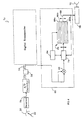
- FIG. 2 is a simplified block diagram of a conventional transponder employing digital signal processing in a mobile cellular communications satellite in which the satellite's transmit antenna is a phased array antenna comprising N array elements 18a, 18b, 18c, ...18n.
- the transponder's uplink antenna 20 receives a plurality of uplink communication carriers 22 which are frequency multiplexed together.
- a wide-band receiver receives the incoming signals and converts them to baseband signals 24.
- An analog-to-digital (A/D) converter samples and quantizes the baseband signals 24 and converts them to discrete time samples 26.
- a digital Fourier transform processor 28 transforms the discrete time samples 26 into discrete frequency samples 30.
- the multi-carrier discrete frequency samples 30 are then channelized and filtered digitally. There are many ways to process the signals digitally.
- the frequency samples 30 are replicated in a replicator 32 into N identical samples 34a, 34b, 34c, ...34n.
- the carrier signals are digitally weighted by multiplying respective predetermined complex weighting coefficients 36a, 36b, 36c, ...36n by an array of complex multipliers 38a, 38b, 38c, ...38n.
- the weighting coefficients 36a, 36b, 36c, ...36n are each designed to change the amplitude and the phase of each of the carrier signals so that a desired antenna beam pattern can be formed from the individual elements 18a, 18b, 18c, ...18n.
- the multiplied frequency-domain signals 40a, 40b, 40c, ...40n are then passed through respective inverse Fourier transform processors 42a, 42b, 42c, ...42n that convert the frequency-domain signals to time-domain digital signals 44a, 44b, 44c, ...44n. These time-domain digital signals are converted in respective digital-to-analog converters (D/A) to analog carrier signals 46a, 46b, 46c, ...46n.
- D/A digital-to-analog converters
- the analog signals 46a, 46b, 46c, ...46n are each amplified and fed to their respective array elements 18a, 18b, 18c, ...18n in a phased array transmit antenna.
- FIG. 3 shows a plot of typical digital Fourier-transformed frequency samples having four carrier frequencies 48a-d in frame 1, 50a-d in frame 2, and 52a-d in frame 3.
- EP 0 501 690 A2 an apparatus for and method of digital signal processing is suggested, wherein it is suggested to demultiplex or multiplex signal channels on board of the satellite for purposes which can include individual channel power control and/or channel to be muting and/or subsequently modulation of the signal channels.
- the present invention relates to a satellite transponder communication carrier power monitoring system as mentioned at the outset comprising an on board carrier power monitor connected to an output of the digital time-to-frequency transform processor such that the discrete frequency samples provided from the output of said digital time-to-frequency transform processor are routed to the on board carrier power monitor in order to digitally compute the power levels of the carriers.
- the present invention provides a system for measuring power levels of individual communication carriers on board a satellite, in which the satellite's transponder uses digital processors to channelize and filter multi-carrier signals, thereby improving the accuracy and reliability of the transponder characterization.
- the digital processor provides a digital power monitor that samples the data stream and computes the mean square power of each carrier's digitized frequency samples.
- This power monitor is particularly suited to a transponder system described in FIG. 2.
- the mean square power levels are encoded and telemetered to an Earth station, which calculates the transponder characteristics.
- a system administrator uses the characterization to control transponder operation and to direct the transmitters to appropriately alter their individual carrier power levels .
- the digital processor can be programmed to characterize the transponder operation and direct any necessary adjustments.
- the present invention provides a system and method for monitoring power levels for individual carriers on board satellites that use a digital processor to channelize and filter multi-carrier uplink signals.
- the digitally filtered and channelized signals are then converted to analog signals, amplified and retransmitted to the Earth.
- the digitized frequency samples 30 of the carriers from the digital Fourier transform processor 28 are used to compute the instantaneous power of each carrier signal. Because the computed power levels are digital, they can easily be stored in memory registers. Because each carrier's time position in the sequence is known, the power level of each carrier can be sent to its assigned memory register. Successive power level computations for each carrier can be added to the computation currently stored in that carrier's memory register to obtain the total energy for each carrier for a period of measurement time (T).
- T measurement time
- P c the average power of a carrier over time T
- T is the time period of measurements
- N is the number of measured samples for each carrier taken in time T
- i is the counter for each measured sample
- V is the amplitude of the carrier in the i th sample.
- FIG. 4 shows an implementation of a system 30 for monitoring the power levels of individual carriers on board a satellite.
- the discrete frequency-sampled output waveform 54 is routed to the on board power monitoring system 60 in addition to being routed to the digital transponder, such as the one depicted in FIG. 2.
- the amplitude of each carrier frequency sample is squared by multiplying the sample to itself in a multiplier 62.
- a timing clock 64 is synchronized to the arrival of each carrier frequency sample.
- the individual memory registers 66a, 66b, ...66n in a memory register bank 66 each stores the power level of a respective carrier.
- all memory registers 66a, 66b, ...66n are flushed with zeros.
- the registers have outputs 68 to a modulator 70 in which the power level data are converted to telemetry RF signals so that the data can be transmitted to an Earth station via a downlink antenna 72.
- the data stored in the memory registers 66 are also routed to an adder 74, which adds the stored power level of a certain carrier to the newly computed power level of that carrier from the multiplier 62. Both the adder 74 and the memory registers 66 are controlled by the synchronized timing clock 64, which ensures that a carrier's power level is added to the power level currently stored in the correct memory register for that carrier.
- FIG. 5 shows a preferred embodiment of a time averaging system at a ground station.
- a satellite 76 transmits the energy data 78 of the carriers to the Earth from an antenna 80.
- a telemetry ground station 82 receives the telemetered data 84 and sends the data to a divider 86, which divides the number representing the accumulated energy of each carrier by time T 88 to obtain a time-averaged power level 90 for each carrier.
- the carriers' power levels 90 are sent to an output device, preferably a bank of N memory registers 92a, 92b, ...92n which store the time-averaged carrier power levels, one register for each carrier.
- the memory registers 92a, 92b, ...92n and the divider 86 are controlled by a timer 94 which is synchronized with the arrival of each carrier's power level to ensure that each power level is stored in the correct memory register.
- the power monitoring system can be incorporated into the digital processor of a transponder that drives a directional antenna to broadcast the multi-carrier signal.
- a power monitor 60 samples the data stream of carrier frequency samples 54 on board the transponder and computes a power level for each of the carriers. This provides accurate and high frequency resolution power measurements within the communications link. These measurements are useful for computing critical transponder characteristics such as the effective isotropic radiated power (EIRP), receiver sensitivity, uplink sensitivity, operating points and, in a system using a phased array antenna, the total and component powers for each beam.
- EIRP effective isotropic radiated power
- the power monitor 60 eliminates problems associated with external measurement methods, and improves the overall accuracy and reliability. Such variations and alternate embodiments are contemplated, and can be made without departing from the scope of the invention as defined in the appended claims.
Landscapes
- Engineering & Computer Science (AREA)
- Physics & Mathematics (AREA)
- General Physics & Mathematics (AREA)
- Computer Networks & Wireless Communication (AREA)
- Signal Processing (AREA)
- Astronomy & Astrophysics (AREA)
- Aviation & Aerospace Engineering (AREA)
- Radio Relay Systems (AREA)
Claims (12)
- Système de surveillance de puissance de porteuse de communications d'un transpondeur satellite, comprenant :un récepteur destiné à recevoir des signaux de communications de liaison montante (22) possédant une pluralité de porteuses, chaque porteuse étant basée sur une fréquence séparée ;un convertisseur analogique/numérique (A/D) relié audit récepteur afin de convertir les signaux de communications reçus (24) en signaux numériques (58), dans un domaine temporel discret ;un processeur de transformation de temps en fréquence numérique (56) relié afin de transformer lesdits signaux numériques (58) dudit domaine temporel discret en échantillons de fréquence discrète (54) qui représentent des porteuses respectives ; etun système de traitement de signaux numériques relié afin de modifier lesdits échantillons de fréquence discrète ;caractérisé par un moniteur de puissance de porteuse intégré (60) relié à une sortie dudit processeur de transformation de temps en fréquence numérique (56) de telle sorte que les échantillons de fréquence discrète (54) fournis par la sortie dudit processeur de transformation de temps en fréquence soient acheminés vers le moniteur de puissance de porteuse intégré (60) afin de calculer numériquement les niveaux de puissance desdites porteuses.
- Système selon la revendication 1, caractérisé en ce que le moniteur de puissance (60) comprend des registres de mémoire respectifs (66) destinés auxdites porteuses afin de stocker les niveaux de puissance calculés à partir des échantillons de fréquence discrète (54) provenant de la sortie dudit processeur de transformation de temps en fréquence numérique (56) dans les registres de mémoire respectifs (66).
- Système selon la revendication 1, caractérisé en ce que ledit moniteur de puissance (60) comprend en outre :un circuit de calcul de puissance (62) relié afin de calculer les puissances desdits échantillons de fréquence discrète (54) provenant dudit processeur de transformation de temps en fréquence numérique (56) ;des registres de mémoire respectifs (66) destinés auxdites porteuses ;un additionneur (74) relié afin d'additionner les puissances calculées par ledit circuit de calcul de puissance (62) aux valeurs conservées dans lesdites registres de mémoire (66) ; etune horloge de synchronisation (64) synchronisant les échantillons de fréquence discrète de chaque porteuse (54) avec lesdits registres de mémoire (66) et ledit additionneur (74) de telle sorte que les puissances calculées des échantillons pour chaque porteuse soient accumulées dans le registre de mémoire de cette porteuse (66) à une vitesse déterminée par ladite horloge de synchronisation (64).
- Système selon les revendications 1 à 3, caractérisé par :un modulateur (70) de fréquence radio (RF) de télémétrie destiné à convertir les données de sortie (68) provenant desdites registres de mémoire (66) représentant les niveaux de puissance des porteuses en signaux RF ; etune antenne de liaison descendante (72) destinée à transmettre lesdits signaux RF à une station terrestre.
- Système selon la revendication 3 ou 4, caractérisé en ce que ledit circuit de calcul de puissance (62) comprend un multiplicateur au carré (62) relié afin de multiplier les amplitudes des échantillons de fréquence discrète (54) par elles-mêmes afin d'obtenir lesdits niveaux de puissance.
- Système selon l'une quelconque des revendications 1, 2, 3 ou 5, caractérisé par une station de télémétrie (82) située sur la terre, ladite station de télémétrie (82) comprenant :un récepteur de télémétrie destiné à recevoir des signaux RF (78) de la part dudit moniteur de puissance de porteuse intégré ;un diviseur (86) relié afin de calculer la puissance moyenne de chaque porteuse à partir des signaux RF reçus (84) ; etun dispositif de sortie (92) destiné audit niveau de puissance calculé.
- Système selon la revendication 6, caractérisé en ce que ledit dispositif de sortie comprend une banque de registres de mémoire de puissance moyenne (92), un registre (92a, ..., 92n) par porteuse, destinés à stocker des niveaux de puissance par porteuse moyennés dans le temps, et un compteur horaire (94) contrôlant l'application de signaux de puissance moyenne pour différentes porteuses entre ledit diviseur (86) et les différents registres de mémoire de puissance moyenne respectifs (92).
- Procédé de calcul de niveaux de puissance pour des porteuses individuelles de transpondeurs satellites, comprenant :la réception de signaux de communications de liaison montante (22) possédant une pluralité de porteuses, chaque porteuse représentant une fréquence séparée ;la conversion desdits signaux (22) en signaux numériques (58) dans un domaine temporel ;la conversion desdits signaux numériques (58) dans le domaine temporel en échantillons de fréquence discrète (54) dans un domaine de fréquences, chaque échantillon de fréquence discrète représentant une porteuse respective ; etla réalisation d'un traitement de signaux numériques sur lesdits échantillons de fréquence discrète ;caractérisé par l'utilisation des échantillons de fréquence discrète (54), qui comprennent une forme d'onde de sortie échantillonnée de fréquence discrète (54) de chaque porteuse en tant que signal d'entrée d'un moniteur de puissance de porteuse intégré (60) afin de calculer les niveaux de puissance desdites porteuses à partir desdits échantillons de fréquence discrète.
- Procédé selon la revendication 8, caractérisé en ce que les niveaux de puissance calculés sont stockés dans des registres de mémoire respectifs (66) des porteuses.
- Procédé selon la revendication 8 ou 9, caractérisé en ce que les niveaux de puissance desdites porteuses sont calculés en :multipliant (62) l'amplitude de l'échantillon de fréquence de chaque porteuse par elle-même à des intervalles de temps successifs, afin d'obtenir des niveaux de puissance de porteuses instantanés ;accumulant (74) lesdits niveaux de puissance de porteuses instantanés de manière séparée pour chaque porteuse pendant une durée (T) qui comprend une pluralité desdits intervalles de temps.
- Procédé selon les revendications 8 à 10, caractérisé en ce que le niveau de puissance instantané accumulé pour chacune desdites porteuses est divisé par T afin d'obtenir un niveau de puissance moyenné dans le temps pour chaque porteuse.
- Procédé selon la revendication 10, caractérisé en ce que le niveau de puissance instantané accumulé de chaque porteuse est transmis à une station terrestre (82), et ladite opération de division par T est effectuée au niveau de ladite station terrestre (82).
Applications Claiming Priority (2)
| Application Number | Priority Date | Filing Date | Title |
|---|---|---|---|
| US709314 | 1996-09-09 | ||
| US08/709,314 US5754942A (en) | 1996-09-09 | 1996-09-09 | Satellite power level monitoring system and method using digital signal processing |
Publications (3)
| Publication Number | Publication Date |
|---|---|
| EP0828352A2 EP0828352A2 (fr) | 1998-03-11 |
| EP0828352A3 EP0828352A3 (fr) | 2003-10-08 |
| EP0828352B1 true EP0828352B1 (fr) | 2006-10-18 |
Family
ID=24849341
Family Applications (1)
| Application Number | Title | Priority Date | Filing Date |
|---|---|---|---|
| EP97114974A Expired - Lifetime EP0828352B1 (fr) | 1996-09-09 | 1997-08-29 | Système et méthode pour surveiller le niveau de puissance d'un satellite utilisant le traitement de signaux numériques |
Country Status (3)
| Country | Link |
|---|---|
| US (1) | US5754942A (fr) |
| EP (1) | EP0828352B1 (fr) |
| DE (1) | DE69736825T2 (fr) |
Families Citing this family (25)
| Publication number | Priority date | Publication date | Assignee | Title |
|---|---|---|---|---|
| US6067453A (en) * | 1996-10-25 | 2000-05-23 | Pt Pasifik Satelit Nusantara | Satellite-based direct access telecommunications systems |
| JPH10336145A (ja) * | 1997-05-30 | 1998-12-18 | Toshiba Corp | 衛星放送システムおよび放送衛星 |
| WO1999021290A1 (fr) * | 1997-10-20 | 1999-04-29 | Comsat Corporation | Procede de mesure et de reduction de decalages de frequence dans des reseaux repartis par satellite/sans fil et systeme de communication correspondant |
| US6141534A (en) * | 1998-03-25 | 2000-10-31 | Spacecode Llc | Communication satellite system with dynamic downlink resource allocation |
| FR2776868B1 (fr) * | 1998-03-30 | 2000-08-11 | Alsthom Cge Alcatel | Compensation de dynamique des signaux pour repeteur de telecommunications spatiales |
| US6496536B2 (en) * | 1999-03-25 | 2002-12-17 | Qualcomm, Incorporated | System and method for estimating power |
| US6937952B2 (en) * | 2001-07-12 | 2005-08-30 | Ses Americom, Inc. | Satellite carrier measurement system and method |
| KR20030024285A (ko) * | 2001-09-17 | 2003-03-26 | 한국전자통신연구원 | 위성통신 시스템에서의 고출력 증폭기 동작점 판단 장치및 그 방법 |
| US6912195B2 (en) * | 2001-12-28 | 2005-06-28 | Motorola, Inc. | Frequency-domain MIMO processing method and system |
| US7024158B2 (en) * | 2002-04-25 | 2006-04-04 | Northrop Grumman Corporation | Broadband communication satellite |
| US6806820B1 (en) | 2003-05-02 | 2004-10-19 | Northrop Grumman Corporation | Analog reconstruction of a digital signal |
| US7372907B2 (en) * | 2003-06-09 | 2008-05-13 | Northrop Grumman Corporation | Efficient and flexible oversampled filterbank with near perfect reconstruction constraint |
| US7268726B2 (en) * | 2003-07-11 | 2007-09-11 | The Boeing Company | Method and apparatus for correction of quantization-induced beacon beam errors |
| US20050007273A1 (en) * | 2003-07-11 | 2005-01-13 | The Boeing Company | Method and apparatus for prediction and correction of gain and phase errors in a beacon or payload |
| US7274329B2 (en) * | 2003-07-11 | 2007-09-25 | The Boeing Company | Method and apparatus for reducing quantization-induced beam errors by selecting quantized coefficients based on predicted beam quality |
| CN100416280C (zh) * | 2005-12-08 | 2008-09-03 | 东南大学 | 感知无线电前端射频信号检测设备 |
| WO2008070504A2 (fr) * | 2006-11-28 | 2008-06-12 | Aviation Communication & Surveillance Systems Llc | Systèmes et procédés pour surveiller la performance d'un transpondeur |
| US9379806B1 (en) * | 2011-11-30 | 2016-06-28 | RKF Engineering Solutions, LLC | EIRP-based beamforming |
| CN103296427B (zh) * | 2013-03-12 | 2016-03-30 | 中国电子科技集团公司第十研究所 | 相控阵天线增益自适应控制的实现方法 |
| US10103804B2 (en) * | 2014-12-31 | 2018-10-16 | Hughes Network Systems, Llc | Apparatus and method for optimizing the power utilization of a satellite spot beam transponder for a multicarrier transmission |
| US9848370B1 (en) * | 2015-03-16 | 2017-12-19 | Rkf Engineering Solutions Llc | Satellite beamforming |
| CN106209278A (zh) * | 2016-07-13 | 2016-12-07 | 国网福建省电力有限公司 | 一种无人直升机旋翼缝隙检测方法 |
| GB2557628B (en) | 2016-12-13 | 2020-01-01 | Inmarsat Global Ltd | Forward link power control |
| WO2022150207A1 (fr) * | 2021-01-07 | 2022-07-14 | Hughes Network Systems, Llc | Compensation de l'atténuation de puissance de porteuse par un trajet de transmission |
| US11533103B2 (en) * | 2021-01-07 | 2022-12-20 | Hughes Network Systems, Llc | Compensation for attenuation of carrier power by a transmission path |
Citations (1)
| Publication number | Priority date | Publication date | Assignee | Title |
|---|---|---|---|---|
| EP0501690A2 (fr) * | 1991-02-28 | 1992-09-02 | Matra Marconi Space UK Limited | Dispositif et procédé de traitement de signaux numériques |
Family Cites Families (6)
| Publication number | Priority date | Publication date | Assignee | Title |
|---|---|---|---|---|
| DE1462183B2 (de) * | 1964-09-11 | 1969-09-25 | Nippon Electric Company Ltd., Tokio | Mehrfachfrequenz-Satellitennachrichtenübertragungssystem |
| CA1196961A (fr) * | 1981-11-16 | 1985-11-19 | Goro Oshima | Systeme de controle de la puissance d'emission d'une station terrienne pour maintenir constante la puissance isotrope rayonnee equivalente des signaux transmis vers la terre quelles que soient les conditions atmospheriques |
| JPS6346824A (ja) * | 1986-08-14 | 1988-02-27 | Kokusai Denshin Denwa Co Ltd <Kdd> | 送信電力制御方式 |
| JP2551650B2 (ja) * | 1989-03-09 | 1996-11-06 | 富士通株式会社 | 送信電力制御方式 |
| JPH04372234A (ja) * | 1991-06-21 | 1992-12-25 | Fujitsu Ltd | 送信電力制御方式 |
| US5613197A (en) * | 1994-11-03 | 1997-03-18 | Hughes Aircraft Co. | Multi-channel transponder with channel amplification at a common lower frequency |
-
1996
- 1996-09-09 US US08/709,314 patent/US5754942A/en not_active Expired - Lifetime
-
1997
- 1997-08-29 DE DE69736825T patent/DE69736825T2/de not_active Expired - Lifetime
- 1997-08-29 EP EP97114974A patent/EP0828352B1/fr not_active Expired - Lifetime
Patent Citations (1)
| Publication number | Priority date | Publication date | Assignee | Title |
|---|---|---|---|---|
| EP0501690A2 (fr) * | 1991-02-28 | 1992-09-02 | Matra Marconi Space UK Limited | Dispositif et procédé de traitement de signaux numériques |
Also Published As
| Publication number | Publication date |
|---|---|
| EP0828352A2 (fr) | 1998-03-11 |
| DE69736825D1 (de) | 2006-11-30 |
| US5754942A (en) | 1998-05-19 |
| EP0828352A3 (fr) | 2003-10-08 |
| DE69736825T2 (de) | 2007-08-23 |
Similar Documents
| Publication | Publication Date | Title |
|---|---|---|
| EP0828352B1 (fr) | Système et méthode pour surveiller le niveau de puissance d'un satellite utilisant le traitement de signaux numériques | |
| EP0304890A2 (fr) | Station terrestre capable d'utiliser efficacement une bande de fréquence d'un satellite | |
| EP0818060B1 (fr) | Appareil et procede de formation du faisceau dans des antennes adaptatives | |
| US6037898A (en) | Method and apparatus for calibrating radio frequency base stations using antenna arrays | |
| US6785300B2 (en) | Delay compensation | |
| EP0860952B1 (fr) | Formation de faisceaux basé terrestre utilisant un multiplexage à division de code synchronisé | |
| RU2101870C1 (ru) | Способ передачи модулированных волн, передающее устройство и приемное устройство | |
| US7068733B2 (en) | Sampling technique for digital beam former | |
| US7426242B2 (en) | Orthogonal frequency digital multiplexing correlation canceller | |
| EP1098390A2 (fr) | Réseau d'émetteur/récepteur pour système de communication par satellite | |
| US5907577A (en) | Delay compensation | |
| US6654618B2 (en) | Variation compensating unit | |
| US12267116B2 (en) | Mutual coupling based calibration | |
| EP0399845B1 (fr) | Indication rapide du niveau d'un signal de réception | |
| EP1133836B1 (fr) | Procede et appareil de calibrage d'une station de radiocommunication a reseau d'antennes | |
| EP0967744A1 (fr) | Procédé et appareil pour la détermination des caractéristiques des composants d'un canal de communication sous charge | |
| JP2006279900A (ja) | 通信装置及びキャリブレーション方法 | |
| US5680143A (en) | Method and apparatus for a low complexity satellite ranging system using Gaussian noise overlay | |
| JP2001086057A (ja) | 無線通信システム | |
| KR20090060035A (ko) | 통신 시스템에서 반향 신호 제거 장치 및 방법 | |
| Loo et al. | Performance analysis and measurement of a saw‐based group demodulator for on‐board processing in communications satellites | |
| HK1000980B (en) | Rapid receiver signal strength indication |
Legal Events
| Date | Code | Title | Description |
|---|---|---|---|
| PUAI | Public reference made under article 153(3) epc to a published international application that has entered the european phase |
Free format text: ORIGINAL CODE: 0009012 |
|
| AK | Designated contracting states |
Kind code of ref document: A2 Designated state(s): AT BE CH DE DK ES FI FR GB GR IE IT LI LU MC NL PT SE |
|
| AX | Request for extension of the european patent |
Free format text: AL;LT;LV;RO;SI |
|
| RAP1 | Party data changed (applicant data changed or rights of an application transferred) |
Owner name: HUGHES ELECTRONICS CORPORATION |
|
| PUAL | Search report despatched |
Free format text: ORIGINAL CODE: 0009013 |
|
| AK | Designated contracting states |
Kind code of ref document: A3 Designated state(s): AT BE CH DE DK ES FI FR GB GR IE IT LI LU MC NL PT SE |
|
| AX | Request for extension of the european patent |
Extension state: AL LT LV RO SI |
|
| 17P | Request for examination filed |
Effective date: 20040330 |
|
| AKX | Designation fees paid |
Designated state(s): DE FR GB |
|
| GRAP | Despatch of communication of intention to grant a patent |
Free format text: ORIGINAL CODE: EPIDOSNIGR1 |
|
| GRAS | Grant fee paid |
Free format text: ORIGINAL CODE: EPIDOSNIGR3 |
|
| GRAA | (expected) grant |
Free format text: ORIGINAL CODE: 0009210 |
|
| AK | Designated contracting states |
Kind code of ref document: B1 Designated state(s): DE FR GB |
|
| REG | Reference to a national code |
Ref country code: GB Ref legal event code: FG4D |
|
| REF | Corresponds to: |
Ref document number: 69736825 Country of ref document: DE Date of ref document: 20061130 Kind code of ref document: P |
|
| ET | Fr: translation filed | ||
| PLBE | No opposition filed within time limit |
Free format text: ORIGINAL CODE: 0009261 |
|
| STAA | Information on the status of an ep patent application or granted ep patent |
Free format text: STATUS: NO OPPOSITION FILED WITHIN TIME LIMIT |
|
| 26N | No opposition filed |
Effective date: 20070719 |
|
| REG | Reference to a national code |
Ref country code: FR Ref legal event code: PLFP Year of fee payment: 20 |
|
| PGFP | Annual fee paid to national office [announced via postgrant information from national office to epo] |
Ref country code: GB Payment date: 20160830 Year of fee payment: 20 Ref country code: DE Payment date: 20160826 Year of fee payment: 20 |
|
| PGFP | Annual fee paid to national office [announced via postgrant information from national office to epo] |
Ref country code: FR Payment date: 20160825 Year of fee payment: 20 |
|
| REG | Reference to a national code |
Ref country code: DE Ref legal event code: R071 Ref document number: 69736825 Country of ref document: DE |
|
| REG | Reference to a national code |
Ref country code: GB Ref legal event code: PE20 Expiry date: 20170828 |
|
| PG25 | Lapsed in a contracting state [announced via postgrant information from national office to epo] |
Ref country code: GB Free format text: LAPSE BECAUSE OF EXPIRATION OF PROTECTION Effective date: 20170828 |