EP0830117B1 - Gelenkloses prothesenfussteil - Google Patents
Gelenkloses prothesenfussteil Download PDFInfo
- Publication number
- EP0830117B1 EP0830117B1 EP96916002A EP96916002A EP0830117B1 EP 0830117 B1 EP0830117 B1 EP 0830117B1 EP 96916002 A EP96916002 A EP 96916002A EP 96916002 A EP96916002 A EP 96916002A EP 0830117 B1 EP0830117 B1 EP 0830117B1
- Authority
- EP
- European Patent Office
- Prior art keywords
- adapter
- foot
- prosthetic
- screw bolt
- supported
- Prior art date
- Legal status (The legal status is an assumption and is not a legal conclusion. Google has not performed a legal analysis and makes no representation as to the accuracy of the status listed.)
- Expired - Lifetime
Links
Images

Classifications
-
- A—HUMAN NECESSITIES
- A61—MEDICAL OR VETERINARY SCIENCE; HYGIENE
- A61F—FILTERS IMPLANTABLE INTO BLOOD VESSELS; PROSTHESES; DEVICES PROVIDING PATENCY TO, OR PREVENTING COLLAPSING OF, TUBULAR STRUCTURES OF THE BODY, e.g. STENTS; ORTHOPAEDIC, NURSING OR CONTRACEPTIVE DEVICES; FOMENTATION; TREATMENT OR PROTECTION OF EYES OR EARS; BANDAGES, DRESSINGS OR ABSORBENT PADS; FIRST-AID KITS
- A61F2/00—Filters implantable into blood vessels; Prostheses, i.e. artificial substitutes or replacements for parts of the body; Appliances for connecting them with the body; Devices providing patency to, or preventing collapsing of, tubular structures of the body, e.g. stents
- A61F2/50—Prostheses not implantable in the body
- A61F2/76—Means for assembling, fitting or testing prostheses, e.g. for measuring or balancing, e.g. alignment means
-
- A—HUMAN NECESSITIES
- A61—MEDICAL OR VETERINARY SCIENCE; HYGIENE
- A61F—FILTERS IMPLANTABLE INTO BLOOD VESSELS; PROSTHESES; DEVICES PROVIDING PATENCY TO, OR PREVENTING COLLAPSING OF, TUBULAR STRUCTURES OF THE BODY, e.g. STENTS; ORTHOPAEDIC, NURSING OR CONTRACEPTIVE DEVICES; FOMENTATION; TREATMENT OR PROTECTION OF EYES OR EARS; BANDAGES, DRESSINGS OR ABSORBENT PADS; FIRST-AID KITS
- A61F2/00—Filters implantable into blood vessels; Prostheses, i.e. artificial substitutes or replacements for parts of the body; Appliances for connecting them with the body; Devices providing patency to, or preventing collapsing of, tubular structures of the body, e.g. stents
- A61F2/50—Prostheses not implantable in the body
- A61F2/60—Artificial legs or feet or parts thereof
- A61F2/66—Feet; Ankle joints
-
- A—HUMAN NECESSITIES
- A61—MEDICAL OR VETERINARY SCIENCE; HYGIENE
- A61F—FILTERS IMPLANTABLE INTO BLOOD VESSELS; PROSTHESES; DEVICES PROVIDING PATENCY TO, OR PREVENTING COLLAPSING OF, TUBULAR STRUCTURES OF THE BODY, e.g. STENTS; ORTHOPAEDIC, NURSING OR CONTRACEPTIVE DEVICES; FOMENTATION; TREATMENT OR PROTECTION OF EYES OR EARS; BANDAGES, DRESSINGS OR ABSORBENT PADS; FIRST-AID KITS
- A61F2/00—Filters implantable into blood vessels; Prostheses, i.e. artificial substitutes or replacements for parts of the body; Appliances for connecting them with the body; Devices providing patency to, or preventing collapsing of, tubular structures of the body, e.g. stents
- A61F2/02—Prostheses implantable into the body
- A61F2/30—Joints
- A61F2002/30001—Additional features of subject-matter classified in A61F2/28, A61F2/30 and subgroups thereof
- A61F2002/30316—The prosthesis having different structural features at different locations within the same prosthesis; Connections between prosthetic parts; Special structural features of bone or joint prostheses not otherwise provided for
- A61F2002/30329—Connections or couplings between prosthetic parts, e.g. between modular parts; Connecting elements
- A61F2002/30331—Connections or couplings between prosthetic parts, e.g. between modular parts; Connecting elements made by longitudinally pushing a protrusion into a complementarily-shaped recess, e.g. held by friction fit
- A61F2002/30354—Cylindrically-shaped protrusion and recess, e.g. cylinder of circular basis
-
- A—HUMAN NECESSITIES
- A61—MEDICAL OR VETERINARY SCIENCE; HYGIENE
- A61F—FILTERS IMPLANTABLE INTO BLOOD VESSELS; PROSTHESES; DEVICES PROVIDING PATENCY TO, OR PREVENTING COLLAPSING OF, TUBULAR STRUCTURES OF THE BODY, e.g. STENTS; ORTHOPAEDIC, NURSING OR CONTRACEPTIVE DEVICES; FOMENTATION; TREATMENT OR PROTECTION OF EYES OR EARS; BANDAGES, DRESSINGS OR ABSORBENT PADS; FIRST-AID KITS
- A61F2/00—Filters implantable into blood vessels; Prostheses, i.e. artificial substitutes or replacements for parts of the body; Appliances for connecting them with the body; Devices providing patency to, or preventing collapsing of, tubular structures of the body, e.g. stents
- A61F2/02—Prostheses implantable into the body
- A61F2/30—Joints
- A61F2002/30001—Additional features of subject-matter classified in A61F2/28, A61F2/30 and subgroups thereof
- A61F2002/30316—The prosthesis having different structural features at different locations within the same prosthesis; Connections between prosthetic parts; Special structural features of bone or joint prostheses not otherwise provided for
- A61F2002/30329—Connections or couplings between prosthetic parts, e.g. between modular parts; Connecting elements
- A61F2002/30433—Connections or couplings between prosthetic parts, e.g. between modular parts; Connecting elements using additional screws, bolts, dowels, rivets or washers e.g. connecting screws
-
- A—HUMAN NECESSITIES
- A61—MEDICAL OR VETERINARY SCIENCE; HYGIENE
- A61F—FILTERS IMPLANTABLE INTO BLOOD VESSELS; PROSTHESES; DEVICES PROVIDING PATENCY TO, OR PREVENTING COLLAPSING OF, TUBULAR STRUCTURES OF THE BODY, e.g. STENTS; ORTHOPAEDIC, NURSING OR CONTRACEPTIVE DEVICES; FOMENTATION; TREATMENT OR PROTECTION OF EYES OR EARS; BANDAGES, DRESSINGS OR ABSORBENT PADS; FIRST-AID KITS
- A61F2/00—Filters implantable into blood vessels; Prostheses, i.e. artificial substitutes or replacements for parts of the body; Appliances for connecting them with the body; Devices providing patency to, or preventing collapsing of, tubular structures of the body, e.g. stents
- A61F2/02—Prostheses implantable into the body
- A61F2/30—Joints
- A61F2002/30001—Additional features of subject-matter classified in A61F2/28, A61F2/30 and subgroups thereof
- A61F2002/30316—The prosthesis having different structural features at different locations within the same prosthesis; Connections between prosthetic parts; Special structural features of bone or joint prostheses not otherwise provided for
- A61F2002/30329—Connections or couplings between prosthetic parts, e.g. between modular parts; Connecting elements
- A61F2002/30474—Connections or couplings between prosthetic parts, e.g. between modular parts; Connecting elements using an intermediate sleeve interposed between both prosthetic parts to be coupled
-
- A—HUMAN NECESSITIES
- A61—MEDICAL OR VETERINARY SCIENCE; HYGIENE
- A61F—FILTERS IMPLANTABLE INTO BLOOD VESSELS; PROSTHESES; DEVICES PROVIDING PATENCY TO, OR PREVENTING COLLAPSING OF, TUBULAR STRUCTURES OF THE BODY, e.g. STENTS; ORTHOPAEDIC, NURSING OR CONTRACEPTIVE DEVICES; FOMENTATION; TREATMENT OR PROTECTION OF EYES OR EARS; BANDAGES, DRESSINGS OR ABSORBENT PADS; FIRST-AID KITS
- A61F2/00—Filters implantable into blood vessels; Prostheses, i.e. artificial substitutes or replacements for parts of the body; Appliances for connecting them with the body; Devices providing patency to, or preventing collapsing of, tubular structures of the body, e.g. stents
- A61F2/02—Prostheses implantable into the body
- A61F2/30—Joints
- A61F2002/30001—Additional features of subject-matter classified in A61F2/28, A61F2/30 and subgroups thereof
- A61F2002/30316—The prosthesis having different structural features at different locations within the same prosthesis; Connections between prosthetic parts; Special structural features of bone or joint prostheses not otherwise provided for
- A61F2002/30329—Connections or couplings between prosthetic parts, e.g. between modular parts; Connecting elements
- A61F2002/30476—Connections or couplings between prosthetic parts, e.g. between modular parts; Connecting elements locked by an additional locking mechanism
- A61F2002/30484—Mechanically expandable devices located on the first prosthetic part for locking into or onto the second prosthetic part
-
- A—HUMAN NECESSITIES
- A61—MEDICAL OR VETERINARY SCIENCE; HYGIENE
- A61F—FILTERS IMPLANTABLE INTO BLOOD VESSELS; PROSTHESES; DEVICES PROVIDING PATENCY TO, OR PREVENTING COLLAPSING OF, TUBULAR STRUCTURES OF THE BODY, e.g. STENTS; ORTHOPAEDIC, NURSING OR CONTRACEPTIVE DEVICES; FOMENTATION; TREATMENT OR PROTECTION OF EYES OR EARS; BANDAGES, DRESSINGS OR ABSORBENT PADS; FIRST-AID KITS
- A61F2/00—Filters implantable into blood vessels; Prostheses, i.e. artificial substitutes or replacements for parts of the body; Appliances for connecting them with the body; Devices providing patency to, or preventing collapsing of, tubular structures of the body, e.g. stents
- A61F2/02—Prostheses implantable into the body
- A61F2/30—Joints
- A61F2002/30001—Additional features of subject-matter classified in A61F2/28, A61F2/30 and subgroups thereof
- A61F2002/30316—The prosthesis having different structural features at different locations within the same prosthesis; Connections between prosthetic parts; Special structural features of bone or joint prostheses not otherwise provided for
- A61F2002/30329—Connections or couplings between prosthetic parts, e.g. between modular parts; Connecting elements
- A61F2002/30476—Connections or couplings between prosthetic parts, e.g. between modular parts; Connecting elements locked by an additional locking mechanism
- A61F2002/30494—Cooperating protrusions and recesses, e.g. radial serrations, located on abutting end surfaces of a longitudinal connection
-
- A—HUMAN NECESSITIES
- A61—MEDICAL OR VETERINARY SCIENCE; HYGIENE
- A61F—FILTERS IMPLANTABLE INTO BLOOD VESSELS; PROSTHESES; DEVICES PROVIDING PATENCY TO, OR PREVENTING COLLAPSING OF, TUBULAR STRUCTURES OF THE BODY, e.g. STENTS; ORTHOPAEDIC, NURSING OR CONTRACEPTIVE DEVICES; FOMENTATION; TREATMENT OR PROTECTION OF EYES OR EARS; BANDAGES, DRESSINGS OR ABSORBENT PADS; FIRST-AID KITS
- A61F2/00—Filters implantable into blood vessels; Prostheses, i.e. artificial substitutes or replacements for parts of the body; Appliances for connecting them with the body; Devices providing patency to, or preventing collapsing of, tubular structures of the body, e.g. stents
- A61F2/50—Prostheses not implantable in the body
- A61F2002/5001—Cosmetic coverings
-
- A—HUMAN NECESSITIES
- A61—MEDICAL OR VETERINARY SCIENCE; HYGIENE
- A61F—FILTERS IMPLANTABLE INTO BLOOD VESSELS; PROSTHESES; DEVICES PROVIDING PATENCY TO, OR PREVENTING COLLAPSING OF, TUBULAR STRUCTURES OF THE BODY, e.g. STENTS; ORTHOPAEDIC, NURSING OR CONTRACEPTIVE DEVICES; FOMENTATION; TREATMENT OR PROTECTION OF EYES OR EARS; BANDAGES, DRESSINGS OR ABSORBENT PADS; FIRST-AID KITS
- A61F2/00—Filters implantable into blood vessels; Prostheses, i.e. artificial substitutes or replacements for parts of the body; Appliances for connecting them with the body; Devices providing patency to, or preventing collapsing of, tubular structures of the body, e.g. stents
- A61F2/50—Prostheses not implantable in the body
- A61F2002/5007—Prostheses not implantable in the body having elastic means different from springs, e.g. including an elastomeric insert
-
- A—HUMAN NECESSITIES
- A61—MEDICAL OR VETERINARY SCIENCE; HYGIENE
- A61F—FILTERS IMPLANTABLE INTO BLOOD VESSELS; PROSTHESES; DEVICES PROVIDING PATENCY TO, OR PREVENTING COLLAPSING OF, TUBULAR STRUCTURES OF THE BODY, e.g. STENTS; ORTHOPAEDIC, NURSING OR CONTRACEPTIVE DEVICES; FOMENTATION; TREATMENT OR PROTECTION OF EYES OR EARS; BANDAGES, DRESSINGS OR ABSORBENT PADS; FIRST-AID KITS
- A61F2/00—Filters implantable into blood vessels; Prostheses, i.e. artificial substitutes or replacements for parts of the body; Appliances for connecting them with the body; Devices providing patency to, or preventing collapsing of, tubular structures of the body, e.g. stents
- A61F2/50—Prostheses not implantable in the body
- A61F2002/5016—Prostheses not implantable in the body adjustable
- A61F2002/5018—Prostheses not implantable in the body adjustable for adjusting angular orientation
-
- A—HUMAN NECESSITIES
- A61—MEDICAL OR VETERINARY SCIENCE; HYGIENE
- A61F—FILTERS IMPLANTABLE INTO BLOOD VESSELS; PROSTHESES; DEVICES PROVIDING PATENCY TO, OR PREVENTING COLLAPSING OF, TUBULAR STRUCTURES OF THE BODY, e.g. STENTS; ORTHOPAEDIC, NURSING OR CONTRACEPTIVE DEVICES; FOMENTATION; TREATMENT OR PROTECTION OF EYES OR EARS; BANDAGES, DRESSINGS OR ABSORBENT PADS; FIRST-AID KITS
- A61F2/00—Filters implantable into blood vessels; Prostheses, i.e. artificial substitutes or replacements for parts of the body; Appliances for connecting them with the body; Devices providing patency to, or preventing collapsing of, tubular structures of the body, e.g. stents
- A61F2/50—Prostheses not implantable in the body
- A61F2/60—Artificial legs or feet or parts thereof
- A61F2/66—Feet; Ankle joints
- A61F2002/6614—Feet
- A61F2002/6657—Feet having a plate-like or strip-like spring element, e.g. an energy-storing cantilever spring keel
-
- A—HUMAN NECESSITIES
- A61—MEDICAL OR VETERINARY SCIENCE; HYGIENE
- A61F—FILTERS IMPLANTABLE INTO BLOOD VESSELS; PROSTHESES; DEVICES PROVIDING PATENCY TO, OR PREVENTING COLLAPSING OF, TUBULAR STRUCTURES OF THE BODY, e.g. STENTS; ORTHOPAEDIC, NURSING OR CONTRACEPTIVE DEVICES; FOMENTATION; TREATMENT OR PROTECTION OF EYES OR EARS; BANDAGES, DRESSINGS OR ABSORBENT PADS; FIRST-AID KITS
- A61F2220/00—Fixations or connections for prostheses classified in groups A61F2/00 - A61F2/26 or A61F2/82 or A61F9/00 or A61F11/00 or subgroups thereof
- A61F2220/0025—Connections or couplings between prosthetic parts, e.g. between modular parts; Connecting elements
- A61F2220/0033—Connections or couplings between prosthetic parts, e.g. between modular parts; Connecting elements made by longitudinally pushing a protrusion into a complementary-shaped recess, e.g. held by friction fit
-
- A—HUMAN NECESSITIES
- A61—MEDICAL OR VETERINARY SCIENCE; HYGIENE
- A61F—FILTERS IMPLANTABLE INTO BLOOD VESSELS; PROSTHESES; DEVICES PROVIDING PATENCY TO, OR PREVENTING COLLAPSING OF, TUBULAR STRUCTURES OF THE BODY, e.g. STENTS; ORTHOPAEDIC, NURSING OR CONTRACEPTIVE DEVICES; FOMENTATION; TREATMENT OR PROTECTION OF EYES OR EARS; BANDAGES, DRESSINGS OR ABSORBENT PADS; FIRST-AID KITS
- A61F2220/00—Fixations or connections for prostheses classified in groups A61F2/00 - A61F2/26 or A61F2/82 or A61F9/00 or A61F11/00 or subgroups thereof
- A61F2220/0025—Connections or couplings between prosthetic parts, e.g. between modular parts; Connecting elements
- A61F2220/0041—Connections or couplings between prosthetic parts, e.g. between modular parts; Connecting elements using additional screws, bolts, dowels or rivets, e.g. connecting screws
Definitions
- the invention relates to a jointless prosthetic foot part one extending from the heel area to the forefoot area
- Inner spring surrounded by a cosmetic covering and connected to an adapter via a screw bolt is a clamp connection for detachable connection a prosthesis tube.
- Such an embodiment can be, for example, the See U.S. Patent 4,645,509.
- the adapter is with this Embodiment by the bolt firmly against one screwed upper stop surface of the inner foot spring and this is arranged immovably opposite.
- the adapter points a clamping sleeve into which the lower end of the prosthesis tube the lower leg prosthesis can be inserted and tightened a separate clamping screw can be clamped.
- US 5,112,356 discloses a ball joint Prosthetic foot part with a from the heel area in the Forefoot inner foot spring extending from a cosmetic Covered and over a bolt is connected to an adapter that connects the lower part of the ball joint forms, the upper joint part in the lower End of a slotted clamping sleeve is integrated, which for releasable connection of a prosthesis tube is used.
- the adapter is based on its design as a cylinder segment and with a serrated underside on a corresponding trained pad of the inner spring from whose The teeth engage positively in the teeth of the adapter.
- the bolt is in the longitudinal direction of the foot extending, one corresponding to the bolt diameter Wide slot of the inner spring inserted and supports itself with its lower end on the underside of one upper horizontal leg of the inner foot spring over a cylinder segment extending across the slot width.
- the ball joint connection can only be completed Unscrew the bolt from the adapter.
- FR 2.148.322 discloses an articulated foot that does not But has a wooden core on which a Cylinder segment is fastened by screws, the top of which Provide open, partially cylindrical wall with teeth is on which there is an adapter with its as a cylinder segment trained and provided with a serrated underside is supported, the two gears interlocking.
- the upward end of the adapter is with a recess into which the lower end of a prosthesis tube is stuck.
- To form a clamping device is a slit in the lower end of the prosthesis tube Inserted sleeve, the one is conical from top to bottom has tapered inner wall in which a clamping nut which is led from below through the wood core and the two cylinder segments inserted screw bolts adjustable in height is.
- This clamp connection has the disadvantage that the clamp is a Widening of the lower end of the prosthesis tube requires so that only thin-walled prosthetic tubes or but only slotted prosthetic tubes can be used. But above all, the stretching of the pipe leads in this region Use of the prosthetic foot part for permanent fracture. The widening the prosthesis tube is not evenly over a sufficiently long pipe section. Because the actual clamp connection between the outer pipe wall and the inner wall of the adapter must, however, the adapter be very rigid a worn clamping surface can hardly be ensured. A high clamping pressure can tear the pipe open under bending load to lead.
- the invention has for its object the above Improve the function of the prosthetic foot part.
- This prosthetic foot part according to the invention enables the intended detent adjustment the setting of various Heel heights.
- the prosthesis tube is centered and clamped through said expansion element.
- the elastomer ring is between an intermediate and an end ring arranged.
- the Bolt is supported on the pressure piece via a spring element.
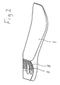
- the prosthetic foot part shown comprises essentially one inner spring extending from the heel area into the forefoot area 1, which is on an interchangeable insert wedge 2 supports the form-fitting between the inner foot spring 1 and the underside 3a of a foot inner spring 1 and insert wedge 2 enclosing cosmetic covering 3 is held.
- Latter can be used as foam cosmetics, as foam cosmetics with reinforced Sole or be designed as a shoe or sandal.
- connection of the prosthetic foot part with a prosthetic tube 4 a lower leg prosthesis takes place via an adapter 5 and a bolt extending through it 6.
- the adapter 5 is supported with its cylinder segment and provided with a toothing 7 bottom on a correspondingly designed connection surface of the inner spring of the foot 1 from, the teeth 8 form-fitting in the teeth 7 of the adapter 5 engages.
- the top end of the adapter 5 is designed as a pin 9 on which the prosthesis tube 4 is stuck with its lower end on one supports annular stop surface 10 of the adapter 5.
- the Bolt 6 is by a extending in the longitudinal direction of the foot a width corresponding to the bolt diameter d b having slot 11 of the inner foot spring 1 and supports itself with its bolt head forming the lower end via a disk 12 on the underside 1a of the inner foot spring 1 from which also in the area surrounding the slot 11 as Cylinder segment is formed, the contour of the bearing surface the disc 12 is adapted.
- the prosthesis tube 4 encloses together with the pin 9 of the Adapters 5 an annular gap, which - seen from the adapter stop surface 10 up - a lower, preferably from Plastic existing end ring 13, an elastomer ring 14, a plastic intermediate ring 15, another elastomer ring 16 and an upper plastic end ring 17 receives.
- the latter is acted upon from above by one on the Adapter pin 9 guided, attached to the inner wall of the Prosthetic tube 4 supporting pressure piece 18.
- Der Bolt 6 is with its upper end through the pressure piece 18 and disc springs 19 resting thereon and equipped with a fastening nut 20, the one for the plate springs 19, the second, opposite the pressure piece 18 Abutment forms.
- the bolt 6 connects all prosthetic foot parts as a central holder with each other and ensures their position in relation on their displaceability in the direction of the longitudinal axis of the leg.
- the screw bolt 6 also serves for application of the attached prosthesis tube 4 with a force fit the adapter pin 9 connecting force. Because putting on the Bolt 6 acts on the pressure piece 18 with a Pin longitudinal direction downward force by which arranged in the annular gap between prosthesis tube 4 and adapter pin 9 Ring packet is axially loaded. This application of force leads to deformation of the elastomer rings 14, 16, which ultimately cause the aforementioned adhesion.
- the prosthesis tube 4 with respect to the adapter pin 9 with respect the longitudinal and torsional forces are secured.
- Das spring element formed by the plate springs 19 controls - without using a torque wrench - that necessarily Torque to be applied to tighten the screw.
- the prosthetic foot part can be constructed on the left and right sides be used.
- the inner foot spring 1 is used for energy storage when rolling and the resulting bend on the tapered End opposite the adapter 5. A sideways sliding of the Adapter 5 is prevented by the shape of the slot 11.
- the insert wedge 2 is used to adjust the foot part to the heel height; by choosing the appropriate wedge change the attenuation.
- the cosmetic covering 3 allows easy adjustment to the foot size.
- the prosthesis tube 4 serves to transfer forces along the longitudinal axis of the leg on the prosthetic foot part; by shortening the Prosthetic tube 4 is an individual in a simple manner Leg length adjustment possible.
Landscapes
- Health & Medical Sciences (AREA)
- Transplantation (AREA)
- Biomedical Technology (AREA)
- Cardiology (AREA)
- Oral & Maxillofacial Surgery (AREA)
- Engineering & Computer Science (AREA)
- Heart & Thoracic Surgery (AREA)
- Vascular Medicine (AREA)
- Life Sciences & Earth Sciences (AREA)
- Animal Behavior & Ethology (AREA)
- General Health & Medical Sciences (AREA)
- Public Health (AREA)
- Veterinary Medicine (AREA)
- Orthopedic Medicine & Surgery (AREA)
- Prostheses (AREA)
Abstract
Description
- Figur 1
- einen lotrechten Längsschnitt durch ein Prothesenfußteil mit angesetztem Prothesenrohr und
- Figur 2
- in schaubildlicher Darstellung die Fußinnenfeder gemäß Figur 1 jedoch in gegenüber der Figur 1 um 180° verdrehter Lage.
Claims (5)
- Gelenkloses Prothesenfußteil mit einer sich vom Fersenbereich in den Vorfußbereich erstreckenden Fußinnenfeder (1), die von einer kosmetischen Verkleidung (3) umschlossen und über einen Schraubbolzen (6) mit einem Adapter (5) verbunden ist, der eine Klemmverbindung zum lösbaren Anschluß eines Prothesenrohres (4) aufweist, mit folgenden Merkmalen:a) der Adapter (5) stützt sich mit seiner als Zylindersegment ausgebildeten und mit einer Verzahnung (7) versehenen Unterseite auf einer entsprechend ausgebildeten Anschlußfläche der Fußinnenfeder (1) ab, deren Verzahnung (8) formschlüssig in die Verzahnung (7) des Adapters (5) eingreift;b) das obere Ende des Adapters (5) ist als Zapfen (9) ausgebildet, auf den das Prothesenrohr (4) gesteckt ist;c) der Schraubbolzen (6) ist durch einen sich in Fußlängsrichtung erstreckenden, eine dem Bolzendurchmesser (d) entsprechende Breite (b) aufweisenden Schlitz (11) der Fußinnenfeder (1) gesteckt und stützt sich mit seinem unteren Ende an der Unterseite (1a) der Fußinnenfeder (1) ab, die im Schlitzbereich ebenfalls als Zylindersegment ausgebildet ist;d) das obere, sich über den Adapterzapfen (9) hinaus erstreckende Ende des Schraubbolzens (6) beaufschlagt die genannte Klemmverbindung, die ein in einem Ringspalt zwischen Adapterzapfen (9) und Prothesenrohr (4) angeordnetes Spreizelement (14, 16) aufweist, das durch Anziehen des Schraubbolzens (6) beaufschlagt wird;e) das Spreizelement weist zumindest einen Elastomerring (14, 16) auf, der sich mit seiner Unterseite direkt oder indirekt auf einer Anschlagfläche (10) des Adapters (5) abstützt und auf seiner Oberseite von einem auf dem Adapterzapfen (9) geführten Druckstück (18) beaufschlagt wird, das seinerseits in Axialrichtung des Schraubbolzens (6) von diesem beaufschlagt wird.
- Prothesenfußteil nach Anspruch 1, dadurch gekennzeichnet, daß der Elastomerring (14, 16) zwischen einem Zwischen- und einem Abschlußring (15, 13, 17) angeordnet ist.
- Prothesenfußteil nach Anspruch 1 oder 2, dadurch gekennzeichnet, daß sich der Schraubbolzen (6) über ein Federelement (19) auf dem Druckstück (18) abstützt.
- Prothesenfußteil nach einem der vorhergehenden Ansprüche, dadurch gekennzeichnet, daß sich die Fußinnenfeder (1) auf einem auswechselbaren Einlegekeil (2) abstützt.
- Prothesenfußteil nach Anspruch 4, dadurch gekennzeichnet, daß der Einlegekeil (2) formschlüssig zwischen der Unterseite (3a) der kosmetischen Verkleidung (3) und der Fußinnenfeder (1) gehalten ist.
Applications Claiming Priority (3)
| Application Number | Priority Date | Filing Date | Title |
|---|---|---|---|
| DE19521147 | 1995-06-09 | ||
| DE19521147A DE19521147C1 (de) | 1995-06-09 | 1995-06-09 | Gelenkloses Prothesenfußteil |
| PCT/DE1996/001031 WO1996041598A1 (de) | 1995-06-09 | 1996-06-05 | Gelenkloses prothesenfussteil |
Publications (2)
| Publication Number | Publication Date |
|---|---|
| EP0830117A1 EP0830117A1 (de) | 1998-03-25 |
| EP0830117B1 true EP0830117B1 (de) | 2000-03-08 |
Family
ID=7764059
Family Applications (1)
| Application Number | Title | Priority Date | Filing Date |
|---|---|---|---|
| EP96916002A Expired - Lifetime EP0830117B1 (de) | 1995-06-09 | 1996-06-05 | Gelenkloses prothesenfussteil |
Country Status (15)
| Country | Link |
|---|---|
| US (1) | US5888239A (de) |
| EP (1) | EP0830117B1 (de) |
| JP (1) | JPH11507282A (de) |
| CN (1) | CN1173812A (de) |
| AR (1) | AR002388A1 (de) |
| AU (1) | AU698110B2 (de) |
| BR (1) | BR9609199A (de) |
| DE (2) | DE19521147C1 (de) |
| ES (1) | ES2115570T1 (de) |
| PL (1) | PL181428B1 (de) |
| RU (1) | RU2151578C1 (de) |
| TR (1) | TR199701338T1 (de) |
| TW (1) | TW338720B (de) |
| WO (1) | WO1996041598A1 (de) |
| ZA (1) | ZA964843B (de) |
Families Citing this family (60)
| Publication number | Priority date | Publication date | Assignee | Title |
|---|---|---|---|---|
| US6206934B1 (en) * | 1998-04-10 | 2001-03-27 | Flex-Foot, Inc. | Ankle block with spring inserts |
| SE511893C2 (sv) * | 1996-07-05 | 1999-12-13 | Pro Pel Ab | Anpassningsbar framfotsdel för en fotprotes; användning av en sådan framfotsdel i en inställbar fotprotes samt system avsett för individuellt anpassningsbara fotproteser |
| DE19756635B4 (de) * | 1996-12-21 | 2005-12-15 | Knecht Maschinenbau Gmbh | Messerbolzen zur drehfesten Positionierung eines Kuttermessers an einer Treibscheibe |
| US6080197A (en) * | 1998-08-13 | 2000-06-27 | Teh Lin Prosthetic & Orthopaedic Inc. | Shock absorbing device for an artificial leg |
| FR2782262B1 (fr) * | 1998-08-17 | 2001-02-09 | Michel Porte | Cotyle d'essai ou implantable a orientation reglable |
| US6261324B1 (en) * | 1999-05-26 | 2001-07-17 | Crp, Inc. | Foot prosthesis |
| SE515958C2 (sv) * | 1999-06-10 | 2001-11-05 | Gramtec Innovation Ab | Anordning vid en benprotes försedd med en fot |
| KR20030070019A (ko) * | 2000-10-26 | 2003-08-27 | 플렉스-푸트, 인크. | 완충발목을 가지는 의족 |
| US7112340B2 (en) * | 2001-10-19 | 2006-09-26 | Baxter International Inc. | Compositions of and method for preparing stable particles in a frozen aqueous matrix |
| JP4808026B2 (ja) * | 2002-08-22 | 2011-11-02 | ヴィクソム ヒューマン バイオニクス インコーポレーテッド | 膝上部肢切断患者用の駆動源付き義足 |
| US7736394B2 (en) * | 2002-08-22 | 2010-06-15 | Victhom Human Bionics Inc. | Actuated prosthesis for amputees |
| US7097666B2 (en) * | 2003-07-25 | 2006-08-29 | American Prosthetic Components, Inc. | Device for angularly coupling prosthetic components |
| US20050027371A1 (en) * | 2003-08-01 | 2005-02-03 | Sen-Jung Chen | Artificial limb with relative position-adjustable upper and lower limb parts |
| US8007544B2 (en) * | 2003-08-15 | 2011-08-30 | Ossur Hf | Low profile prosthetic foot |
| US20050107889A1 (en) | 2003-11-18 | 2005-05-19 | Stephane Bedard | Instrumented prosthetic foot |
| US7815689B2 (en) | 2003-11-18 | 2010-10-19 | Victhom Human Bionics Inc. | Instrumented prosthetic foot |
| US20050137717A1 (en) * | 2003-12-18 | 2005-06-23 | Finn Gramnas | Prosthetic foot with rocker member |
| US20060184280A1 (en) * | 2005-02-16 | 2006-08-17 | Magnus Oddsson | System and method of synchronizing mechatronic devices |
| US7637959B2 (en) | 2004-02-12 | 2009-12-29 | össur hf | Systems and methods for adjusting the angle of a prosthetic ankle based on a measured surface angle |
| EP1718252B1 (de) | 2004-02-12 | 2018-01-10 | Össur hf | Vorrichtung und verfahren zur bewegungssteuerung eines fusses |
| CA2559890C (en) | 2004-03-10 | 2014-01-07 | Ossur Hf | Control system and method for a prosthetic knee |
| US8128709B2 (en) * | 2004-05-28 | 2012-03-06 | össur hf | Functional foot cover |
| US7542876B2 (en) * | 2004-06-25 | 2009-06-02 | Johnson Controls Technology Company | Method of and apparatus for evaluating the performance of a control system |
| CA2863933C (en) | 2004-12-22 | 2018-08-07 | Ossur Hf | Systems and methods for processing limb motion |
| US8048007B2 (en) | 2005-02-02 | 2011-11-01 | össur hf | Prosthetic and orthotic systems usable for rehabilitation |
| US8801802B2 (en) * | 2005-02-16 | 2014-08-12 | össur hf | System and method for data communication with a mechatronic device |
| SE528516C2 (sv) * | 2005-04-19 | 2006-12-05 | Lisa Gramnaes | Kombinerat aktivt och passivt benprotessystem samt en metod för att utföra en rörelsecykel med ett sådant system |
| DE102005031185A1 (de) * | 2005-07-01 | 2007-01-04 | Otto Bock Healthcare Ip Gmbh & Co. Kg | Orthopädietechnisches Hilfsmittel, insbesondere Prothese für eine Extremität |
| US7531006B2 (en) | 2005-09-01 | 2009-05-12 | össur hf | Sensing system and method for motion-controlled foot unit |
| EP1942843B1 (de) * | 2005-09-01 | 2017-03-01 | Össur hf | Vorrichtung und verfahren zur bestimmung der änderung des terrains |
| US8048172B2 (en) | 2005-09-01 | 2011-11-01 | össur hf | Actuator assembly for prosthetic or orthotic joint |
| US7503937B2 (en) * | 2006-07-03 | 2009-03-17 | Ossur Hf | Prosthetic foot |
| CN101553191B (zh) | 2006-07-03 | 2013-03-13 | 奥苏尔公司 | 假足 |
| US7824446B2 (en) * | 2006-12-06 | 2010-11-02 | Freedom Innovations, Llc | Prosthetic foot with longer upper forefoot and shorter lower forefoot |
| US7727285B2 (en) * | 2007-01-30 | 2010-06-01 | Freedom Innovations, Llc | Prosthetic foot with variable medial/lateral stiffness |
| US11020248B2 (en) | 2007-09-19 | 2021-06-01 | Proteor USA, LLC | Vacuum system for a prosthetic foot |
| US12011373B2 (en) | 2007-09-19 | 2024-06-18 | Proteor USA, LLC | Mounting bracket for connecting a prosthetic limb to a prosthetic foot |
| US10405998B2 (en) | 2007-09-19 | 2019-09-10 | Ability Dynamics Llc | Mounting bracket for connecting a prosthetic limb to a prosthetic foot |
| CN102036626B (zh) | 2008-03-24 | 2014-07-02 | 奥瑟Hf公司 | 经股的假肢系统和用于操作该系统的方法 |
| US8685109B2 (en) | 2008-07-01 | 2014-04-01 | össur hf | Smooth rollover insole for prosthetic foot |
| US9060884B2 (en) | 2011-05-03 | 2015-06-23 | Victhom Human Bionics Inc. | Impedance simulating motion controller for orthotic and prosthetic applications |
| US9114029B2 (en) | 2011-09-20 | 2015-08-25 | össur hf | Dorsi-plantar prosthetic ankle module |
| US8961618B2 (en) | 2011-12-29 | 2015-02-24 | össur hf | Prosthetic foot with resilient heel |
| US20130204397A1 (en) * | 2012-02-02 | 2013-08-08 | Elwin Isaac Nordman, JR. | Prosthetic foot covering enabling rapid conversion between shoe and barefoot walking |
| US9017419B1 (en) | 2012-03-09 | 2015-04-28 | össur hf | Linear actuator |
| WO2014126768A1 (en) | 2013-02-13 | 2014-08-21 | össur hf | Overmould attachments for prosthetic foot |
| EP3427702B1 (de) | 2013-02-26 | 2024-12-18 | Össur HF | Fussprothese mit verbesserter stabilität und elastischer energierückspeisung |
| DE102014006687A1 (de) | 2014-05-09 | 2015-11-12 | Otto Bock Healthcare Gmbh | Prothesenfuß |
| US20160175118A1 (en) * | 2014-12-18 | 2016-06-23 | Fountainhead, Llc | Prosthetic spacer devices, systems, and methods |
| WO2016115395A1 (en) | 2015-01-15 | 2016-07-21 | Ability Dynamics, Llc | Prosthetic foot |
| CN105055053B (zh) * | 2015-08-18 | 2017-06-13 | 陕西福音假肢有限责任公司 | 可调式假肢踝关节 |
| US9949850B2 (en) | 2015-09-18 | 2018-04-24 | Össur Iceland Ehf | Magnetic locking mechanism for prosthetic or orthotic joints |
| WO2018102609A1 (en) | 2016-12-01 | 2018-06-07 | Össur Iceland Ehf | Prosthetic feet having heel height adjustability |
| FR3063887B3 (fr) | 2017-03-17 | 2019-12-13 | Pm Ingenierie Et Design | Prothese de pied a lame |
| US11446164B1 (en) | 2017-09-15 | 2022-09-20 | Össur Iceland Ehf | Variable stiffness mechanisms |
| US10980648B1 (en) | 2017-09-15 | 2021-04-20 | Össur Iceland Ehf | Variable stiffness mechanism and limb support device incorporating the same |
| US12414867B1 (en) | 2018-06-01 | 2025-09-16 | Össur Iceland Ehf | Prosthetic feet with increased flexibility to accommodate different heel heights |
| JP2021058318A (ja) * | 2019-10-04 | 2021-04-15 | BionicM株式会社 | 義足の足部及び義足 |
| DE102019134984A1 (de) * | 2019-12-18 | 2021-06-24 | Ottobock Se & Co. Kgaa | Fußkosmetik-System |
| DE102020120498B4 (de) * | 2020-08-04 | 2022-03-31 | Ottobock Se & Co. Kgaa | Prothesenfuß |
Family Cites Families (15)
| Publication number | Priority date | Publication date | Assignee | Title |
|---|---|---|---|---|
| FR2148322B1 (de) * | 1971-07-22 | 1975-02-07 | Proteor Sa | |
| FR2410998A1 (fr) * | 1977-12-08 | 1979-07-06 | Lebre Patrick | Dispositif de reglage pour protheses tubulaires |
| SU848023A1 (ru) * | 1979-10-25 | 1981-07-23 | Центральный Ордена Трудового Красногознамени Научно-Исследовательскийинститут Протезирования И Протезостроения | Искусственна стопа |
| GB2098072B (en) * | 1980-09-25 | 1984-03-21 | Blatchford & Sons Chas A Ltd | Improved endo-skeletal artificial limb |
| US4387472A (en) * | 1980-10-02 | 1983-06-14 | Medical Center Prosthetics, Inc. | Torque absorber with biofeedback |
| US4555817A (en) * | 1983-07-18 | 1985-12-03 | Mckendrick Roderick W | Prosthetic foot and ankle joint |
| US4645509A (en) * | 1984-06-11 | 1987-02-24 | Model & Instrument Development Corporation | Prosthetic foot having a cantilever spring keel |
| SU1424831A1 (ru) * | 1985-12-20 | 1988-09-23 | Специальное Экспериментальное Конструкторско-Технологическое Бюро Министерства Социального Обеспечения | Искусственна стопа |
| CA1305585C (en) * | 1986-07-28 | 1992-07-28 | Robert E. Arbogast | Prosthetic foot |
| SU1593652A1 (ru) * | 1987-12-17 | 1990-09-23 | Ф.А.Ткач | Голеностопный узел по Ф.А.Ткачу |
| US5112356A (en) * | 1988-03-04 | 1992-05-12 | Chas A. Blatchford & Sons Limited | Lower limb prosthesis with means for restricting dorsi-flexion |
| JPH01305803A (ja) * | 1988-05-31 | 1989-12-11 | Daikin Ind Ltd | 塩酸の精製法 |
| EP0444883A1 (de) * | 1990-02-28 | 1991-09-04 | CHAS. A. BLATCHFORD & SONS LIMITED | Kunstfuss |
| DE4209974C1 (de) * | 1992-03-27 | 1993-04-15 | Otto Bock Orthopaedische Industrie Besitz- Und Verwaltungs-Kommanditgesellschaft, 3408 Duderstadt, De | |
| US5769896A (en) * | 1994-09-30 | 1998-06-23 | Brent Rosendahl | Prosthetic foot with ankle |
-
1995
- 1995-06-09 DE DE19521147A patent/DE19521147C1/de not_active Expired - Fee Related
-
1996
- 1996-06-05 ES ES96916002T patent/ES2115570T1/es active Pending
- 1996-06-05 CN CN96191788A patent/CN1173812A/zh active Pending
- 1996-06-05 DE DE59604607T patent/DE59604607D1/de not_active Expired - Fee Related
- 1996-06-05 BR BR9609199A patent/BR9609199A/pt not_active Application Discontinuation
- 1996-06-05 EP EP96916002A patent/EP0830117B1/de not_active Expired - Lifetime
- 1996-06-05 US US08/894,693 patent/US5888239A/en not_active Expired - Fee Related
- 1996-06-05 AU AU58923/96A patent/AU698110B2/en not_active Ceased
- 1996-06-05 RU RU97112184/14A patent/RU2151578C1/ru active
- 1996-06-05 JP JP9502497A patent/JPH11507282A/ja active Pending
- 1996-06-05 WO PCT/DE1996/001031 patent/WO1996041598A1/de not_active Ceased
- 1996-06-05 TR TR97/01338T patent/TR199701338T1/xx unknown
- 1996-06-05 PL PL96321658A patent/PL181428B1/pl unknown
- 1996-06-07 AR ARP960103031A patent/AR002388A1/es active IP Right Grant
- 1996-06-07 ZA ZA964843A patent/ZA964843B/xx unknown
- 1996-07-18 TW TW085106765A patent/TW338720B/zh active
Also Published As
| Publication number | Publication date |
|---|---|
| EP0830117A1 (de) | 1998-03-25 |
| JPH11507282A (ja) | 1999-06-29 |
| US5888239A (en) | 1999-03-30 |
| AR002388A1 (es) | 1998-03-11 |
| TR199701338T1 (xx) | 1998-02-21 |
| PL321658A1 (en) | 1997-12-22 |
| WO1996041598A1 (de) | 1996-12-27 |
| TW338720B (en) | 1998-08-21 |
| RU2151578C1 (ru) | 2000-06-27 |
| PL181428B1 (en) | 2001-07-31 |
| BR9609199A (pt) | 1999-05-11 |
| DE59604607D1 (de) | 2000-04-13 |
| ZA964843B (en) | 1997-01-07 |
| CN1173812A (zh) | 1998-02-18 |
| AU5892396A (en) | 1997-01-09 |
| ES2115570T1 (es) | 1998-07-01 |
| AU698110B2 (en) | 1998-10-22 |
| DE19521147C1 (de) | 1996-12-05 |
Similar Documents
| Publication | Publication Date | Title |
|---|---|---|
| EP0830117B1 (de) | Gelenkloses prothesenfussteil | |
| DE69316617T2 (de) | Fussprothese | |
| DE69004726T2 (de) | Vorrichtung zur Befestigung von mechanischen Teilen an der Karosserie eines Kraftfahrzeugs. | |
| EP0938872B1 (de) | Schwenkbares Befestigungssystem an einer Knochenschraube | |
| DE69116534T2 (de) | Äussere Fixatur zur Osteosynthese | |
| EP0011258B1 (de) | Vorrichtung zur äusseren Festlegung der Teile eines gebrochenen Knochens | |
| EP0243298B1 (de) | Bausatz für eine Schaftprothese | |
| DE3245330C2 (de) | Künstliches Körperteil | |
| DE3787811T2 (de) | Beinprothese. | |
| DE3104353A1 (de) | Gelenkstativ | |
| EP0603114A1 (de) | Klemmvorrichtung | |
| WO1992020298A1 (de) | Implantat mit pressfläche | |
| DE3441417C1 (de) | Pferdehufschuh | |
| EP0260671B1 (de) | Schläger für Ballspiele, insbesondere Tennisspiele, sowie Bespannvorrichtung hierzu | |
| DE2726963C3 (de) | Vorrichtung zum Abziehen eines Zylinderteiles von einem Schneckenextruder | |
| DE102012012173B4 (de) | Vorrichtung zum Einstellen einer Beinprothese und Verfahren zum Erstellen einer derartigen Vorrichtung | |
| DE2433358C2 (de) | Dentaltechnisches Geschiebe zur lösbaren Befestigung von Zahnprothesen am Restgebiß | |
| EP0564889A1 (de) | Verbindungseinrichtung für ein insbesondere rohrförmiges Bauteil | |
| EP0298909B1 (de) | Extrakoronales, aktivierbares Geschiebe | |
| EP2491888B1 (de) | Verankerungsvorrichtung zum Befestigen von orthodontischen Drähten für eine kieferorthopädische Korrekturvorrichtung | |
| DE8908137U1 (de) | Befestigungselement | |
| EP0937546B1 (de) | Klemm- und Trennvorrichtung, insbesondere zum Abziehen von Lagerschalen dienende Vorrichtung | |
| DE4139700A1 (de) | Vorrichtung zum externen festlegen von knockenfragmenten | |
| EP0893057B1 (de) | Offener Hufbeschlag aus Kunststoff | |
| DE2809704C2 (de) | Mittelholmtreppe |
Legal Events
| Date | Code | Title | Description |
|---|---|---|---|
| PUAI | Public reference made under article 153(3) epc to a published international application that has entered the european phase |
Free format text: ORIGINAL CODE: 0009012 |
|
| 17P | Request for examination filed |
Effective date: 19970710 |
|
| AK | Designated contracting states |
Kind code of ref document: A1 Designated state(s): DE ES FR GB IT |
|
| ITCL | It: translation for ep claims filed |
Representative=s name: MODIANO & ASSOCIATI S.R.L. |
|
| GBC | Gb: translation of claims filed (gb section 78(7)/1977) | ||
| EL | Fr: translation of claims filed | ||
| REG | Reference to a national code |
Ref country code: ES Ref legal event code: BA2A Ref document number: 2115570 Country of ref document: ES Kind code of ref document: T1 |
|
| GRAG | Despatch of communication of intention to grant |
Free format text: ORIGINAL CODE: EPIDOS AGRA |
|
| GRAG | Despatch of communication of intention to grant |
Free format text: ORIGINAL CODE: EPIDOS AGRA |
|
| GRAH | Despatch of communication of intention to grant a patent |
Free format text: ORIGINAL CODE: EPIDOS IGRA |
|
| 17Q | First examination report despatched |
Effective date: 19990811 |
|
| GRAH | Despatch of communication of intention to grant a patent |
Free format text: ORIGINAL CODE: EPIDOS IGRA |
|
| GRAA | (expected) grant |
Free format text: ORIGINAL CODE: 0009210 |
|
| AK | Designated contracting states |
Kind code of ref document: B1 Designated state(s): DE ES FR GB IT |
|
| PG25 | Lapsed in a contracting state [announced via postgrant information from national office to epo] |
Ref country code: IT Free format text: LAPSE BECAUSE OF FAILURE TO SUBMIT A TRANSLATION OF THE DESCRIPTION OR TO PAY THE FEE WITHIN THE PRE;WARNING: LAPSES OF ITALIAN PATENTS WITH EFFECTIVE DATE BEFORE 2007 MAY HAVE OCCURRED AT ANY TIME BEFORE 2007. THE CORRECT EFFECTIVE DATE MAY BE DIFFERENT FROM THE ONE RECORDED.SCRIBED TIME-LIMIT Effective date: 20000308 |
|
| REF | Corresponds to: |
Ref document number: 59604607 Country of ref document: DE Date of ref document: 20000413 |
|
| GBT | Gb: translation of ep patent filed (gb section 77(6)(a)/1977) |
Effective date: 20000330 |
|
| ET | Fr: translation filed | ||
| PG25 | Lapsed in a contracting state [announced via postgrant information from national office to epo] |
Ref country code: ES Free format text: LAPSE BECAUSE OF FAILURE TO SUBMIT A TRANSLATION OF THE DESCRIPTION OR TO PAY THE FEE WITHIN THE PRESCRIBED TIME-LIMIT Effective date: 20000919 |
|
| PLBE | No opposition filed within time limit |
Free format text: ORIGINAL CODE: 0009261 |
|
| STAA | Information on the status of an ep patent application or granted ep patent |
Free format text: STATUS: NO OPPOSITION FILED WITHIN TIME LIMIT |
|
| 26N | No opposition filed | ||
| PGFP | Annual fee paid to national office [announced via postgrant information from national office to epo] |
Ref country code: DE Payment date: 20010615 Year of fee payment: 6 |
|
| PGFP | Annual fee paid to national office [announced via postgrant information from national office to epo] |
Ref country code: FR Payment date: 20010628 Year of fee payment: 6 |
|
| REG | Reference to a national code |
Ref country code: GB Ref legal event code: IF02 |
|
| PGFP | Annual fee paid to national office [announced via postgrant information from national office to epo] |
Ref country code: GB Payment date: 20020522 Year of fee payment: 7 |
|
| PG25 | Lapsed in a contracting state [announced via postgrant information from national office to epo] |
Ref country code: DE Free format text: LAPSE BECAUSE OF NON-PAYMENT OF DUE FEES Effective date: 20030101 |
|
| PG25 | Lapsed in a contracting state [announced via postgrant information from national office to epo] |
Ref country code: FR Free format text: LAPSE BECAUSE OF NON-PAYMENT OF DUE FEES Effective date: 20030228 |
|
| REG | Reference to a national code |
Ref country code: FR Ref legal event code: ST |
|
| PG25 | Lapsed in a contracting state [announced via postgrant information from national office to epo] |
Ref country code: GB Free format text: LAPSE BECAUSE OF NON-PAYMENT OF DUE FEES Effective date: 20030605 |
|
| GBPC | Gb: european patent ceased through non-payment of renewal fee |
Effective date: 20030605 |