EP0833049A1 - Vanne à commande électrique et à ouverture continue en fonctionnement, pour régénération de canister - Google Patents
Vanne à commande électrique et à ouverture continue en fonctionnement, pour régénération de canister Download PDFInfo
- Publication number
- EP0833049A1 EP0833049A1 EP97402207A EP97402207A EP0833049A1 EP 0833049 A1 EP0833049 A1 EP 0833049A1 EP 97402207 A EP97402207 A EP 97402207A EP 97402207 A EP97402207 A EP 97402207A EP 0833049 A1 EP0833049 A1 EP 0833049A1
- Authority
- EP
- European Patent Office
- Prior art keywords
- valve
- canister
- chamber
- seat
- pressure
- Prior art date
- Legal status (The legal status is an assumption and is not a legal conclusion. Google has not performed a legal analysis and makes no representation as to the accuracy of the status listed.)
- Granted
Links
- 230000008929 regeneration Effects 0.000 title claims description 16
- 238000011069 regeneration method Methods 0.000 title claims description 16
- 239000000446 fuel Substances 0.000 claims abstract description 26
- 238000002485 combustion reaction Methods 0.000 claims abstract description 7
- 238000010926 purge Methods 0.000 claims description 16
- 230000033001 locomotion Effects 0.000 claims description 9
- 238000011144 upstream manufacturing Methods 0.000 claims description 7
- 239000000203 mixture Substances 0.000 claims description 4
- 125000004122 cyclic group Chemical group 0.000 claims 1
- 239000002828 fuel tank Substances 0.000 abstract description 5
- QVGXLLKOCUKJST-UHFFFAOYSA-N atomic oxygen Chemical compound [O] QVGXLLKOCUKJST-UHFFFAOYSA-N 0.000 abstract description 3
- 239000000463 material Substances 0.000 abstract description 3
- 229910052760 oxygen Inorganic materials 0.000 abstract description 3
- 239000001301 oxygen Substances 0.000 abstract description 3
- 239000007789 gas Substances 0.000 abstract description 2
- 238000011084 recovery Methods 0.000 abstract description 2
- 239000003570 air Substances 0.000 description 8
- 239000012528 membrane Substances 0.000 description 6
- 230000006870 function Effects 0.000 description 5
- 239000012080 ambient air Substances 0.000 description 4
- 238000002347 injection Methods 0.000 description 4
- 239000007924 injection Substances 0.000 description 4
- 210000000056 organ Anatomy 0.000 description 4
- OKTJSMMVPCPJKN-UHFFFAOYSA-N Carbon Chemical compound [C] OKTJSMMVPCPJKN-UHFFFAOYSA-N 0.000 description 2
- 230000009471 action Effects 0.000 description 2
- 239000000523 sample Substances 0.000 description 2
- 208000031968 Cadaver Diseases 0.000 description 1
- 239000002250 absorbent Substances 0.000 description 1
- 230000002745 absorbent Effects 0.000 description 1
- 239000003463 adsorbent Substances 0.000 description 1
- 238000010276 construction Methods 0.000 description 1
- 230000037213 diet Effects 0.000 description 1
- 235000005911 diet Nutrition 0.000 description 1
- 238000006073 displacement reaction Methods 0.000 description 1
- 230000000694 effects Effects 0.000 description 1
- 230000005284 excitation Effects 0.000 description 1
- 238000009434 installation Methods 0.000 description 1
- 238000005259 measurement Methods 0.000 description 1
- 235000001954 papillon Nutrition 0.000 description 1
- 244000229285 papillon Species 0.000 description 1
- 230000009467 reduction Effects 0.000 description 1
- 230000000717 retained effect Effects 0.000 description 1
- 229920006395 saturated elastomer Polymers 0.000 description 1
- 230000007480 spreading Effects 0.000 description 1
Images
Classifications
-
- F—MECHANICAL ENGINEERING; LIGHTING; HEATING; WEAPONS; BLASTING
- F02—COMBUSTION ENGINES; HOT-GAS OR COMBUSTION-PRODUCT ENGINE PLANTS
- F02M—SUPPLYING COMBUSTION ENGINES IN GENERAL WITH COMBUSTIBLE MIXTURES OR CONSTITUENTS THEREOF
- F02M25/00—Engine-pertinent apparatus for adding non-fuel substances or small quantities of secondary fuel to combustion-air, main fuel or fuel-air mixture
- F02M25/08—Engine-pertinent apparatus for adding non-fuel substances or small quantities of secondary fuel to combustion-air, main fuel or fuel-air mixture adding fuel vapours drawn from engine fuel reservoir
- F02M25/0836—Arrangement of valves controlling the admission of fuel vapour to an engine, e.g. valve being disposed between fuel tank or absorption canister and intake manifold
-
- F—MECHANICAL ENGINEERING; LIGHTING; HEATING; WEAPONS; BLASTING
- F02—COMBUSTION ENGINES; HOT-GAS OR COMBUSTION-PRODUCT ENGINE PLANTS
- F02M—SUPPLYING COMBUSTION ENGINES IN GENERAL WITH COMBUSTIBLE MIXTURES OR CONSTITUENTS THEREOF
- F02M25/00—Engine-pertinent apparatus for adding non-fuel substances or small quantities of secondary fuel to combustion-air, main fuel or fuel-air mixture
- F02M25/08—Engine-pertinent apparatus for adding non-fuel substances or small quantities of secondary fuel to combustion-air, main fuel or fuel-air mixture adding fuel vapours drawn from engine fuel reservoir
- F02M2025/0845—Electromagnetic valves
Definitions
- the invention relates to an electrically controlled valve. and with continuous opening in operation, for a circuit of regeneration of a canister associated with a combustion engine internal, supplied with air or air powered by at least an intake duct, in which the flow is controlled by a throttling member, for example of the rotary type commonly known as a butterfly.
- the invention relates to a valve with a continuous canister purge flow and modulated by an electrical signal, for the regeneration of a canister associated with an internal combustion engine including the fuel system can either have a carburetor, the throttle of which rotary, or throttle valve, controls the mixing flow air-fuel, or be of the so-called "injection" type and have a butterfly body, including the throttling member rotary controls the intake air flow to the engine.
- the canister is a receptacle collecting fuel vapors from various organs containing or traveled by fuel, in the circuit followed by the fuel in the vehicle and its engine, and in particular the fuel tank, as well as the engine, and injection tubing and injector (s), or, if applicable if applicable, from the carburetor.
- the canister in which these fuel vapors are collected to avoid their release into the ambient air, is fitted with a vent in communication with the atmosphere, so that the fuel tank is vented to the through the canister.
- a circuit regeneration system comprising a valve mounted on a pipeline connecting the canister to the intake duct, downstream of the throttle organ.
- the arrival of this fuel air in the engine changes the richness of the air-fuel mixture prepared by the carburetor or the or the injectors, depending on the case, which receive (s) orders from control developed from signals from different engine operating parameter sensors, and in particular a probe measuring the oxygen level in engine exhaust.
- solenoid valves comprising a calibrator with constant flow section and a check valve flow control, linked in motion to a nucleus of a solenoid, whose coil is supplied with electric current at rectangular slots with opening duty cycle variable, i.e. the opening time, for a constant period, corresponds to a variable fraction of this period, corresponding to the length of the current used.
- the variation of the flow is thus obtained by modulating the cross section of the calibration, subjected to the vacuum of the motor, this modulation being ensured by the valve the solenoid valve.
- the electrically operated valve for a canister regeneration circuit of the type presented above comprising a pipe connecting the canister to the intake duct, downstream of the organ and on which is mounted the valve which includes a calibrator with constant passage section, a flow control valve in the pipeline and that is linked in motion to a nucleus of a solenoid whose coil is powered by an electric current to control the force on the valve, is such that the valve is integral in motion of a flexible membrane, which delimits, in a case, two bedrooms, the first of which is kept at a pressure close to or equal to atmospheric pressure, and whose second chamber is modulated vacuum, encloses the valve and communicates through an orifice input, with the canister via the calibrator, and through an outlet with the intake duct, the membrane thus subjected to a depression close to or equal to that which acts on the calibrator being also subject to the opposing efforts of elastic means, which tend to close the valve on the outlet, and the solenoid, the coil of which develops
- the membrane In operation, the membrane is in equilibrium under the combined actions of elastic means, which tend to recall the valve in the closed position, of the effort magnetic due to the solenoid, and therefore of the current which crosses its coil, and finally depression, which determines the flow, this depression being the differential pressure between atmospheric pressure or a pressure close to the latter and reigning in the first chamber, and the control pressure in the second chamber.
- This valve thus allows modulate the regeneration flow continuously by through a variable depression determined at using an average control current.
- this valve has the disadvantage that full opening, very significant efforts are exerted on the membrane, due to the strong depression at which this membrane is then submitted (and which can reach 60kPa when the engine is running at idle).
- the solenoid of this valve must therefore be able to develop significant magnetic forces, at the cost of significant current consumption.
- the valve according to the invention of a type known from FR 2 699 603, and which includes a calibrator with constant passage section and a housing defining a room connected by an entrance with the canister and through an outlet with the intake duct, and in which a valve for controlling the purge flow of the canister is mounted movable relative to a lockable seat by the valve, which is linked in movement to a nucleus of a solenoid whose coil is powered by a current electric medium variable to control the effort on the valve and its spacing from the seat in the open position of the valve, is characterized in that the outlet from the chamber is connected to the intake duct via the calibrator so the pressure downstream of the calibrator is the pressure in the duct downstream of the throttle member, while the entrance to the bedroom is directly connected to the canister by the pipeline, so that the upstream of the seat is at atmospheric pressure or at a pressure close to the latter, and the purge flow through the calibrator is continuously modulated by modulation of the pressure difference at the valve resulting from the modulation of
- a valve does not have a membrane and that the section of its valve may be small, we understand than a small solenoid, low power and low consumption may be enough to control the valve of the valve, the structure of which can thus be simpler and more economical.
- the valve may further comprise means elastic return biasing the valve to its position closing against the seat, the power supply of the solenoid coil developing a magnetic force urging the valve against the elastic means in seat open position.
- valve does not does not have elastic return means, and, in this case, when the engine stops, the solenoid coil is powered by an electric current such that the valve is subjected to a magnetic force applying it against its seat in the valve closed position.
- Such a valve is advantageously supplied with variable mean current obtained by supplying the coil of the solenoid by rectangular electrical current slots with variable duty cycle.
- the current variable means can be controlled by a control device sensitive to at least one signal from at least one sensor for an engine operating parameter, such as a richness sensor of the air-fuel mixture, and / or a pressure sensor in the downstream intake duct of the throttling organ.
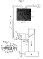
- the canister 1 contains a material 2 absorbent or adsorbent, for example activated carbon, which takes care of fuel vapors coming in particular of the fuel tank R, and which are brought to the canister 1 through the recovery line 3.
- Canister 1 which can thus contain for example 100 g of fuel, is provided with a vent 4 connecting it to the atmosphere, and is also connected to the intake duct 5 of a carburetor body or a throttle body of an internal combustion engine M.
- a throttle member or butterfly 6 is rotatably mounted in the conduit 5, and the angular position of the butterfly 6 in the duct 5 is controlled to regulate the intake flow air, in the case of a throttle body, or carburetted air, in the case of a carburetor.
- a circuit 7 of canister regeneration 1 includes a regeneration line 8, which opens at its entrance, in canister 1, and, at its exit, in the duct 5, as well as an electrically controlled valve 9, connected between the upstream 8a and downstream 8b branches of the pipeline 8.
- the valve 9 is a check valve whose position is controlled by a solenoid receiving current electrical control of a control device schematically represented in 10, and which is a control unit engine control electronics, including a computer comprising at least one microprocessor or microcontroller, and in particular ensuring the control and command of the ignition and injection, in the case of an injection engine, from information received from multiple sensors engine operating parameters.
- the valve 9 comprises a body or case 11, of generally cylindrical shape, delimiting an internal chamber 12, which has an orifice inlet 13, connected to the upstream part 8a of the pipeline 8 of regeneration of canister 1, as well as an orifice of outlet 14, connected to the downstream part 8b of the pipeline 8 by a tubular endpiece 15 containing a calibrator 16 or restriction, with constant passage section.
- the suburbs of the inlet 13 constitutes a seat 17 for a valve 18.
- This valve 18 is in one piece, by a rod 19, with the substantially cylindrical core 20, of a solenoid comprising an excitation coil 21 fixed in the chamber 12 of the body 11, and in which are axially engaged the core 20 and the rod 19.
- valve 9 is normally closed when the motor M.
- This closure is ensured, in this example, by a helical return spring 22, bearing on the valve 18 and on a support of the coil 21, and surrounding the part of the rod 19 located between the coil 21 and the valve 18, to push the valve 18 towards its seat 17, so closing the inlet 13 when the coil 21 is not not powered.
- the coil 21 is traversed by a average control electric current, which results from supply of rectangular current slots to variable duty cycle.
- the 18-core valve assembly 20 is then subjected to an electromagnetic force Fm, which spreads the valve 18 of its seat 17 and of the inlet orifice 13, at against the spring 22 exerting a restoring force Fr.
- La chamber 12 is then in communication with the pipeline upstream 8a and canister 1 via inlet 13 and via outlet 14 with the intake duct 5, through the calibrator 16.
- the pressure in chamber 12 is a pressure of control or command Pc which is then intermediate between the pressure of the Pcan canister, upstream of the inlet 13, itself near atmospheric pressure Pa, and the pressure downstream of calibrator 16, which is the manifold pressure engine intake M, i.e. the prevailing pressure in the intake duct 5, downstream of the butterfly 6.
- the regeneration rate Q passing through the calibrator 16 is a function of Sc, ⁇ , Pc and Pcol according to a formula F1 (Sc, ⁇ , Pc, Pcol) which is tabulated in the unit of command 10, and where Sc is the constant passage section of the calibrator 16, ⁇ the density of the air-fuel mixture from canister 1, and Pcol and Pc are respectively the manifold pressure, in the duct 5 downstream of the throttle valve 6, and the control pressure in chamber 12, the manifold pressure being known by the installation, because transmitted to the control unit 10 by a pressure 23, detecting the pressure in the intake duct 5 downstream of the butterfly 6.
- the pressure drop ⁇ p at the level of the valve 18 is equal to the force applied to the valve 18, divided by the section s of the valve 18.
- the force which requests the valve 18 is the difference between the magnetic force Fm, exerted on the core 20 by the current supply of the coil 21 of the solenoid, and the restoring force Fr exerted by the spring 22 on the valve 18.
- the flow rate Q is a function of the mean current I passing through the solenoid coil 21, the relation of formula (4) being a known characteristic solenoid 20-21.
- the relationship between the flow of purge Q and the average current I flowing in the coil 21 can be calculated or tabulated in memory in the unit of control 10.
- the average current I applied to the coil 21 is obtained by a variable duty cycle command, at a sufficiently high frequency, around 100 Hz for example. It is thus possible to control a continuous purge flow rate Q, by action on the power supply duty cycle of the valve solenoid 9.
- the operating principle is therefore based on the pressure drop regulation or pressure difference at the level of the valve 18, and not of a variable section, for modulate the purge flow as required, and taking particular account of the Pcol pressure at the manifold engine intake M.
- the purge flow Q of canister 1, delivered by the valve 9, is continuous and modulated by the modulation of the force electromagnetic Fm, itself a function of the average current of control I of the coil 21.
- the valve 9 is thus at flow continuous and modulated by the electric control current. So that this valve 9 is relatively insensitive to vibrations of the motor M, a threshold spring 22 is chosen low effort, but sufficient for this purpose.
- valve 9 can be without a spring 22, in which case the coil 21 remains supplied, after stopping the engine, for a sufficient time and in a proper direction to hold the valve 18 by magnetic force against seat 17 in entry 13 closed position of the body 11.
- valve 18 can cooperate with a seat 17 formed around the orifice of outlet 14 of chamber 12, in which case the pressure of command Pc considered is the pressure prevailing in the tubular section 15 between the calibrator 16 and the outlet 14.
- valve 18 is not not directly integral in movement with the core 20, as this is ensured by making a single piece of the valve 18 with the core 20 by the rod 19, and the valve 18 can be linked in motion to the core 20 by means of reduction in the amplitude of movement of the valve 18 relative to the amplitude of displacement of the core 20.
- a valve which modulates the regeneration flow so continuous, by modulating the pressure drop at the level of the valve, this modulation being determined by the modulation the spacing between the valve 18 and the seat 17, this spacing being itself modulated by the modulation of the average electric current applied to the coil 21.
- the solenoid can be small, low power and low electrical consumption, therefore inexpensive, in a valve simple and economical structure.
- This electric current is supplied for example by a control unit for a carburetor or a control unit an engine control system, integrated into the command 10, and this current can be developed from information from, in particular, a wealth finder 24, of the lambda probe type detecting the oxygen content in engine exhaust gases passing through the manifold exhaust 25, as well as the pressure sensor 23, as explained above.
Landscapes
- Engineering & Computer Science (AREA)
- Chemical & Material Sciences (AREA)
- Combustion & Propulsion (AREA)
- Mechanical Engineering (AREA)
- General Engineering & Computer Science (AREA)
- Magnetically Actuated Valves (AREA)
- Supplying Secondary Fuel Or The Like To Fuel, Air Or Fuel-Air Mixtures (AREA)
Abstract
Description
- la figure 1 représente schématiquement un circuit de régénération de canister, équipé d'une vanne selon l'invention, et monté entre un canister et un conduit d'admission d'un carburateur ou corps de papillon de moteur à combustion interne, et
- la figure 2 est une vue schématique en coupe longitudinale d'un exemple de vanne.
Claims (10)
- Vanne à commande électrique et à ouverture continue en fonctionnement, pour la régénération d'un canister (1) associé à un moteur à combustion interne (M) alimenté en air ou air carburé par au moins un conduit d'admission (5) dans lequel le débit est commandé par un organe d'étranglement mobile (6), le canister (1) dans lequel des vapeurs de carburant sont collectées étant, d'une part, muni d'un évent (4) en communication avec l'atmosphère et, d'autre part, raccordé au conduit d'admission (5) en aval de l'organe d'étranglement (6) par une canalisation (8) sur laquelle est montée ladite vanne (9), qui comprend un calibreur (16) à section de passage constante et un boítier (11) délimitant une chambre (12) mise en communication par une entrée (13) avec le canister (1) et par une sortie (14) avec le conduit d'admission (5), et dans laquelle un clapet (18) de commande du débit de purge du canister (1) est monté mobile par rapport à un siège (17) obturable par le clapet (18), qui est lié en mouvement à un noyau (20) d'un solénoïde dont la bobine (21) est alimentée par un courant électrique moyen variable (I) pour commander l'effort sur le clapet (18) et son écartement du siège (17) en position d'ouverture de la vanne (9),
caractérisée en ce que la sortie (14) de la chambre (12) est reliée au conduit d'admission (5) par l'intermédiaire du calibreur (16) de sorte que la pression en aval du calibreur (16) est la pression dans le conduit (5) en aval de l'organe d'étranglement (6), tandis que l'entrée (13) de la chambre (12) est directement reliée au canister (1) par la canalisation (8), de sorte que l'amont du siège (17) est à la pression atmosphérique ou à une pression voisine de cette dernière, et le débit de purge traversant le calibreur (16) est modulé de façon continue par modulation de la différence de pression au niveau du clapet (18) résultant de la modulation de l'effort appliqué au clapet (18) par la modulation du courant moyen variable (I) dans la bobine (21). - Vanne selon la revendication 1, caractérisée en ce qu'elle comprend de plus des moyens élastiques (22) de rappel sollicitant le clapet (18) vers sa position de fermeture contre le siège (17), et en ce que l'alimentation électrique de la bobine (21) du solénoïde développe une force magnétique (Fm) sollicitant le clapet (18) contre les moyens élastiques (22) en position d'ouverture du siège (17).
- Vanne selon la revendication 1, caractérisée en ce qu'à l'arrêt du moteur (M), la bobine (21) du solénoïde est alimentée par un courant électrique tel que le clapet (18) est soumis à une force magnétique l'appliquant contre son siège (17) en position de fermeture de la vanne (9).
- Vanne selon l'une quelconque des revendications 1 à 3, caractérisée en ce que le courant moyen variable (I) est obtenu en alimentant la bobine (21) du solénoïde par des créneaux de courant électrique rectangulaires à rapport cyclique variable.
- Vanne selon l'une quelconque des revendications 1 à 4, caractérisée en ce que le courant moyen variable (I) est piloté par un organe (10) de commande sensible à au moins un signal provenant d'au moins un capteur d'un paramètre de fonctionnement du moteur (M), tel qu'un capteur de richesse (24) du mélange air-combustible, et/ou un capteur de pression (23) dans le conduit d'admission (5) en aval de l'organe d'étranglement (6).
- Vanne selon l'une quelconque des revendications 1 à 5, caractérisée en ce que le siège (17) est aménagé autour de l'entrée (13) de la chambre (12).
- Vanne selon l'une quelconque des revendications 1 à 6, caractérisée en ce que le clapet (18) est directement solidaire en mouvement du noyau (20) qui est logé avec la bobine (21) du solénoïde dans la chambre (12) de la vanne (9).
- Vanne selon la revendication 7, caractérisée en ce que la chambre (12) est délimitée dans un boítier (11) de forme sensiblement cylindrique, et le clapet (18), le siège (17), l'entrée (13) de la chambre (12), le noyau (20) et la bobine (21) du solénoïde et, éventuellement, la sortie (14) de la chambre (12), sont sensiblement coaxiaux à l'axe longitudinal du boítier (11).
- Vanne selon l'une quelconque des revendications 7 et 8, caractérisée en ce que le clapet (18) est d'une seule pièce avec le noyau (20) par une tige (19) au moins partiellement engagée axialement avec le noyau (20) dans la bobine (21) du solénoïde.
- Vanne selon la revendication 9, telle que rattachée à la revendication 3, caractérisée en ce que les moyens élastiques de rappel comprennent au moins un ressort hélicoïdal (22) logé dans la chambre (12) entre le clapet (18) et un support de la bobine (21) dans la chambre (12) de la vanne (9).
Applications Claiming Priority (2)
| Application Number | Priority Date | Filing Date | Title |
|---|---|---|---|
| FR9611744A FR2753747B1 (fr) | 1996-09-26 | 1996-09-26 | Vanne a commande electrique et a ouverture continue en fonctionnement, pour regeneration d'un collecteur de vapeurs de carburant |
| FR9611744 | 1996-09-26 |
Publications (2)
| Publication Number | Publication Date |
|---|---|
| EP0833049A1 true EP0833049A1 (fr) | 1998-04-01 |
| EP0833049B1 EP0833049B1 (fr) | 2000-04-12 |
Family
ID=9496090
Family Applications (1)
| Application Number | Title | Priority Date | Filing Date |
|---|---|---|---|
| EP19970402207 Expired - Lifetime EP0833049B1 (fr) | 1996-09-26 | 1997-09-23 | Vanne à commande électrique et à ouverture continue en fonctionnement, pour régénération de canister |
Country Status (4)
| Country | Link |
|---|---|
| EP (1) | EP0833049B1 (fr) |
| DE (1) | DE69701663T2 (fr) |
| ES (1) | ES2146070T3 (fr) |
| FR (1) | FR2753747B1 (fr) |
Cited By (2)
| Publication number | Priority date | Publication date | Assignee | Title |
|---|---|---|---|---|
| FR2778784A1 (fr) * | 1998-05-13 | 1999-11-19 | Renault | Procede de commande d'une electrovanne, notamment d'un circuit de purge canister d'un moteur |
| WO2011012638A3 (fr) * | 2009-07-31 | 2011-04-07 | Knorr-Bremse Systeme für Nutzfahrzeuge GmbH | Vanne magnétique et procédé de fonctionnement d'une vanne magnétique |
Citations (5)
| Publication number | Priority date | Publication date | Assignee | Title |
|---|---|---|---|---|
| US4086897A (en) * | 1976-12-28 | 1978-05-02 | Toyota Jidosha Kogyo Kabushiki Kaisha | Evaporated fuel feed control device for an internal combustion engine |
| US4127097A (en) * | 1976-12-15 | 1978-11-28 | Toyota Jidosha Kogyo Kabushiki Kaisha | Fuel evaporation control system |
| US5284121A (en) * | 1991-07-26 | 1994-02-08 | Nippon Soken, Inc. | Internal combustion engine with evaporated fuel purge system |
| FR2699603A1 (fr) * | 1992-12-21 | 1994-06-24 | Solex | Vanne à commande électrique de circuit de régénération de canister. |
| US5509395A (en) * | 1995-03-31 | 1996-04-23 | Siemens Electric Limited | Canister purge flow regulator |
-
1996
- 1996-09-26 FR FR9611744A patent/FR2753747B1/fr not_active Expired - Fee Related
-
1997
- 1997-09-23 EP EP19970402207 patent/EP0833049B1/fr not_active Expired - Lifetime
- 1997-09-23 DE DE1997601663 patent/DE69701663T2/de not_active Expired - Lifetime
- 1997-09-23 ES ES97402207T patent/ES2146070T3/es not_active Expired - Lifetime
Patent Citations (5)
| Publication number | Priority date | Publication date | Assignee | Title |
|---|---|---|---|---|
| US4127097A (en) * | 1976-12-15 | 1978-11-28 | Toyota Jidosha Kogyo Kabushiki Kaisha | Fuel evaporation control system |
| US4086897A (en) * | 1976-12-28 | 1978-05-02 | Toyota Jidosha Kogyo Kabushiki Kaisha | Evaporated fuel feed control device for an internal combustion engine |
| US5284121A (en) * | 1991-07-26 | 1994-02-08 | Nippon Soken, Inc. | Internal combustion engine with evaporated fuel purge system |
| FR2699603A1 (fr) * | 1992-12-21 | 1994-06-24 | Solex | Vanne à commande électrique de circuit de régénération de canister. |
| US5509395A (en) * | 1995-03-31 | 1996-04-23 | Siemens Electric Limited | Canister purge flow regulator |
Cited By (2)
| Publication number | Priority date | Publication date | Assignee | Title |
|---|---|---|---|---|
| FR2778784A1 (fr) * | 1998-05-13 | 1999-11-19 | Renault | Procede de commande d'une electrovanne, notamment d'un circuit de purge canister d'un moteur |
| WO2011012638A3 (fr) * | 2009-07-31 | 2011-04-07 | Knorr-Bremse Systeme für Nutzfahrzeuge GmbH | Vanne magnétique et procédé de fonctionnement d'une vanne magnétique |
Also Published As
| Publication number | Publication date |
|---|---|
| FR2753747A1 (fr) | 1998-03-27 |
| DE69701663T2 (de) | 2000-11-23 |
| DE69701663D1 (de) | 2000-05-18 |
| ES2146070T3 (es) | 2000-07-16 |
| FR2753747B1 (fr) | 1998-11-27 |
| EP0833049B1 (fr) | 2000-04-12 |
Similar Documents
| Publication | Publication Date | Title |
|---|---|---|
| EP0301944B1 (fr) | Dispositif de récupération de vapeurs d'essence | |
| FR2851610A1 (fr) | Procede et dispositif de gestion d'un moteur a combustion interne | |
| FR2727185A1 (fr) | Clapet d'electrovanne et circuit de recyclage de vapeurs d'essence de moteur a combustion interne | |
| FR2482198A1 (fr) | Systeme de controle de recirculation des gaz d'echappement pour un moteur diesel | |
| FR2935751A1 (fr) | Procede, dispositif et systeme de fonctionnement d'un moteur a combustion interne | |
| FR2479907A1 (fr) | Soupape d'injection de carburant | |
| FR2507685A1 (fr) | Dispositif de manoeuvre de volet des gaz pour systeme d'injection de carburant a commande electronique | |
| EP0604285B1 (fr) | Vanne à commande électrique de circuit de régénération de canister | |
| EP0833049B1 (fr) | Vanne à commande électrique et à ouverture continue en fonctionnement, pour régénération de canister | |
| CA1242620A (fr) | Methode et dispositifs a reponse rapide permettant de deceler une mauvaise combustion | |
| FR2463287A1 (fr) | Dispositif et procede de commande du rapport air-combustible pour un carburateur de moteur a combustion interne | |
| EP0030979B1 (fr) | Dispositif d'injection de combustible | |
| CH609789A5 (en) | Fluid-regulation device, especially for the feed to an internal- combustion engine | |
| FR2494774A1 (fr) | Dispositif de commande du rapport air-combustible pour moteur a combustion interne | |
| FR2487007A1 (fr) | Dispositif de commande du rapport air-combustible pour le carburateur d'un moteur a combustion interne | |
| FR2492890A1 (fr) | Dispositif de commande du rapport air/combustible pour moteur a combustion interne | |
| FR2617908A1 (fr) | Systeme d'injection de carburant pour moteurs a combustion interne | |
| EP0077286A1 (fr) | Détendeur-vaporisateur à injection électronique pour moteur à gaz de pétrole liquéfié | |
| EP0014603B1 (fr) | Méthode et dispositif de mesure du taux de recirculation de gaz d'échappement dans un moteur à combustion interne | |
| FR2756376A1 (fr) | Procede pour determiner le debit a travers une vanne de regeneration d'une installation de ventilation de reservoir d'automobile | |
| FR2475125A1 (fr) | Dispositif de commande du melange pour moteur de vehicule a recyclage des gaz d'echappement | |
| FR2499159A1 (fr) | Dispositif d'admission de melange air-carburant pour moteur a combustion interne | |
| FR2567964A1 (fr) | Dispositif pour controler la richesse du melange admis dans un moteur a combustion interne | |
| FR2610995A1 (fr) | Dispositif de carburation a venturi elastique variable et gestion electronique pour moteurs a explosions | |
| FR3027062A1 (fr) | Procede de commande d'un moteur a combustion interne muni d'un dispositif de traitement de gaz |
Legal Events
| Date | Code | Title | Description |
|---|---|---|---|
| PUAI | Public reference made under article 153(3) epc to a published international application that has entered the european phase |
Free format text: ORIGINAL CODE: 0009012 |
|
| AK | Designated contracting states |
Kind code of ref document: A1 Designated state(s): DE ES GB IT SE |
|
| AX | Request for extension of the european patent |
Free format text: AL;LT;LV;RO;SI |
|
| 17P | Request for examination filed |
Effective date: 19980502 |
|
| AKX | Designation fees paid |
Free format text: DE ES GB IT SE |
|
| RBV | Designated contracting states (corrected) |
Designated state(s): DE ES GB IT SE |
|
| GRAG | Despatch of communication of intention to grant |
Free format text: ORIGINAL CODE: EPIDOS AGRA |
|
| 17Q | First examination report despatched |
Effective date: 19990128 |
|
| GRAG | Despatch of communication of intention to grant |
Free format text: ORIGINAL CODE: EPIDOS AGRA |
|
| GRAH | Despatch of communication of intention to grant a patent |
Free format text: ORIGINAL CODE: EPIDOS IGRA |
|
| GRAH | Despatch of communication of intention to grant a patent |
Free format text: ORIGINAL CODE: EPIDOS IGRA |
|
| GRAA | (expected) grant |
Free format text: ORIGINAL CODE: 0009210 |
|
| AK | Designated contracting states |
Kind code of ref document: B1 Designated state(s): DE ES GB IT SE |
|
| REF | Corresponds to: |
Ref document number: 69701663 Country of ref document: DE Date of ref document: 20000518 |
|
| ITF | It: translation for a ep patent filed | ||
| REG | Reference to a national code |
Ref country code: ES Ref legal event code: FG2A Ref document number: 2146070 Country of ref document: ES Kind code of ref document: T3 |
|
| GBT | Gb: translation of ep patent filed (gb section 77(6)(a)/1977) |
Effective date: 20000626 |
|
| PLBE | No opposition filed within time limit |
Free format text: ORIGINAL CODE: 0009261 |
|
| STAA | Information on the status of an ep patent application or granted ep patent |
Free format text: STATUS: NO OPPOSITION FILED WITHIN TIME LIMIT |
|
| 26N | No opposition filed | ||
| REG | Reference to a national code |
Ref country code: GB Ref legal event code: IF02 |
|
| PGFP | Annual fee paid to national office [announced via postgrant information from national office to epo] |
Ref country code: ES Payment date: 20090828 Year of fee payment: 13 |
|
| PGFP | Annual fee paid to national office [announced via postgrant information from national office to epo] |
Ref country code: SE Payment date: 20090925 Year of fee payment: 13 Ref country code: GB Payment date: 20090922 Year of fee payment: 13 |
|
| PGFP | Annual fee paid to national office [announced via postgrant information from national office to epo] |
Ref country code: DE Payment date: 20100922 Year of fee payment: 14 |
|
| REG | Reference to a national code |
Ref country code: SE Ref legal event code: EUG |
|
| GBPC | Gb: european patent ceased through non-payment of renewal fee |
Effective date: 20100923 |
|
| PG25 | Lapsed in a contracting state [announced via postgrant information from national office to epo] |
Ref country code: GB Free format text: LAPSE BECAUSE OF NON-PAYMENT OF DUE FEES Effective date: 20100923 |
|
| REG | Reference to a national code |
Ref country code: ES Ref legal event code: FD2A Effective date: 20111019 |
|
| PG25 | Lapsed in a contracting state [announced via postgrant information from national office to epo] |
Ref country code: ES Free format text: LAPSE BECAUSE OF NON-PAYMENT OF DUE FEES Effective date: 20100924 |
|
| PGFP | Annual fee paid to national office [announced via postgrant information from national office to epo] |
Ref country code: IT Payment date: 20110916 Year of fee payment: 15 |
|
| PG25 | Lapsed in a contracting state [announced via postgrant information from national office to epo] |
Ref country code: SE Free format text: LAPSE BECAUSE OF NON-PAYMENT OF DUE FEES Effective date: 20100924 |
|
| PG25 | Lapsed in a contracting state [announced via postgrant information from national office to epo] |
Ref country code: DE Free format text: LAPSE BECAUSE OF NON-PAYMENT OF DUE FEES Effective date: 20130403 |
|
| PG25 | Lapsed in a contracting state [announced via postgrant information from national office to epo] |
Ref country code: IT Free format text: LAPSE BECAUSE OF NON-PAYMENT OF DUE FEES Effective date: 20120923 |
|
| REG | Reference to a national code |
Ref country code: DE Ref legal event code: R119 Ref document number: 69701663 Country of ref document: DE Effective date: 20130403 |