EP0834037B1 - Low capacity chlorine gas feed system - Google Patents
Low capacity chlorine gas feed system Download PDFInfo
- Publication number
- EP0834037B1 EP0834037B1 EP96918492A EP96918492A EP0834037B1 EP 0834037 B1 EP0834037 B1 EP 0834037B1 EP 96918492 A EP96918492 A EP 96918492A EP 96918492 A EP96918492 A EP 96918492A EP 0834037 B1 EP0834037 B1 EP 0834037B1
- Authority
- EP
- European Patent Office
- Prior art keywords
- gas
- valve
- diaphragm
- inlet
- vacuum
- Prior art date
- Legal status (The legal status is an assumption and is not a legal conclusion. Google has not performed a legal analysis and makes no representation as to the accuracy of the status listed.)
- Expired - Lifetime
Links
Images




Classifications
-
- F—MECHANICAL ENGINEERING; LIGHTING; HEATING; WEAPONS; BLASTING
- F17—STORING OR DISTRIBUTING GASES OR LIQUIDS
- F17C—VESSELS FOR CONTAINING OR STORING COMPRESSED, LIQUEFIED OR SOLIDIFIED GASES; FIXED-CAPACITY GAS-HOLDERS; FILLING VESSELS WITH, OR DISCHARGING FROM VESSELS, COMPRESSED, LIQUEFIED, OR SOLIDIFIED GASES
- F17C13/00—Details of vessels or of the filling or discharging of vessels
- F17C13/04—Arrangement or mounting of valves
-
- F—MECHANICAL ENGINEERING; LIGHTING; HEATING; WEAPONS; BLASTING
- F17—STORING OR DISTRIBUTING GASES OR LIQUIDS
- F17C—VESSELS FOR CONTAINING OR STORING COMPRESSED, LIQUEFIED OR SOLIDIFIED GASES; FIXED-CAPACITY GAS-HOLDERS; FILLING VESSELS WITH, OR DISCHARGING FROM VESSELS, COMPRESSED, LIQUEFIED, OR SOLIDIFIED GASES
- F17C13/00—Details of vessels or of the filling or discharging of vessels
- F17C13/04—Arrangement or mounting of valves
- F17C13/045—Automatic change-over switching assembly for bottled gas systems with two (or more) gas containers
-
- C—CHEMISTRY; METALLURGY
- C02—TREATMENT OF WATER, WASTE WATER, SEWAGE, OR SLUDGE
- C02F—TREATMENT OF WATER, WASTE WATER, SEWAGE, OR SLUDGE
- C02F1/00—Treatment of water, waste water, or sewage
- C02F1/72—Treatment of water, waste water, or sewage by oxidation
- C02F1/76—Treatment of water, waste water, or sewage by oxidation with halogens or compounds of halogens
- C02F1/763—Devices for the addition of such compounds in gaseous form
-
- F—MECHANICAL ENGINEERING; LIGHTING; HEATING; WEAPONS; BLASTING
- F16—ENGINEERING ELEMENTS AND UNITS; GENERAL MEASURES FOR PRODUCING AND MAINTAINING EFFECTIVE FUNCTIONING OF MACHINES OR INSTALLATIONS; THERMAL INSULATION IN GENERAL
- F16K—VALVES; TAPS; COCKS; ACTUATING-FLOATS; DEVICES FOR VENTING OR AERATING
- F16K1/00—Lift valves or globe valves, i.e. cut-off apparatus with closure members having at least a component of their opening and closing motion perpendicular to the closing faces
- F16K1/32—Details
- F16K1/34—Cutting-off parts, e.g. valve members, seats
- F16K1/44—Details of seats or valve members of double-seat valves
-
- F—MECHANICAL ENGINEERING; LIGHTING; HEATING; WEAPONS; BLASTING
- F16—ENGINEERING ELEMENTS AND UNITS; GENERAL MEASURES FOR PRODUCING AND MAINTAINING EFFECTIVE FUNCTIONING OF MACHINES OR INSTALLATIONS; THERMAL INSULATION IN GENERAL
- F16K—VALVES; TAPS; COCKS; ACTUATING-FLOATS; DEVICES FOR VENTING OR AERATING
- F16K31/00—Actuating devices; Operating means; Releasing devices
- F16K31/44—Mechanical actuating means
- F16K31/53—Mechanical actuating means with toothed gearing
- F16K31/54—Mechanical actuating means with toothed gearing with pinion and rack
-
- F—MECHANICAL ENGINEERING; LIGHTING; HEATING; WEAPONS; BLASTING
- F17—STORING OR DISTRIBUTING GASES OR LIQUIDS
- F17C—VESSELS FOR CONTAINING OR STORING COMPRESSED, LIQUEFIED OR SOLIDIFIED GASES; FIXED-CAPACITY GAS-HOLDERS; FILLING VESSELS WITH, OR DISCHARGING FROM VESSELS, COMPRESSED, LIQUEFIED, OR SOLIDIFIED GASES
- F17C2201/00—Vessel construction, in particular geometry, arrangement or size
- F17C2201/01—Shape
- F17C2201/0104—Shape cylindrical
- F17C2201/0109—Shape cylindrical with exteriorly curved end-piece
-
- F—MECHANICAL ENGINEERING; LIGHTING; HEATING; WEAPONS; BLASTING
- F17—STORING OR DISTRIBUTING GASES OR LIQUIDS
- F17C—VESSELS FOR CONTAINING OR STORING COMPRESSED, LIQUEFIED OR SOLIDIFIED GASES; FIXED-CAPACITY GAS-HOLDERS; FILLING VESSELS WITH, OR DISCHARGING FROM VESSELS, COMPRESSED, LIQUEFIED, OR SOLIDIFIED GASES
- F17C2201/00—Vessel construction, in particular geometry, arrangement or size
- F17C2201/01—Shape
- F17C2201/0104—Shape cylindrical
- F17C2201/0119—Shape cylindrical with flat end-piece
-
- F—MECHANICAL ENGINEERING; LIGHTING; HEATING; WEAPONS; BLASTING
- F17—STORING OR DISTRIBUTING GASES OR LIQUIDS
- F17C—VESSELS FOR CONTAINING OR STORING COMPRESSED, LIQUEFIED OR SOLIDIFIED GASES; FIXED-CAPACITY GAS-HOLDERS; FILLING VESSELS WITH, OR DISCHARGING FROM VESSELS, COMPRESSED, LIQUEFIED, OR SOLIDIFIED GASES
- F17C2201/00—Vessel construction, in particular geometry, arrangement or size
- F17C2201/03—Orientation
- F17C2201/032—Orientation with substantially vertical main axis
-
- F—MECHANICAL ENGINEERING; LIGHTING; HEATING; WEAPONS; BLASTING
- F17—STORING OR DISTRIBUTING GASES OR LIQUIDS
- F17C—VESSELS FOR CONTAINING OR STORING COMPRESSED, LIQUEFIED OR SOLIDIFIED GASES; FIXED-CAPACITY GAS-HOLDERS; FILLING VESSELS WITH, OR DISCHARGING FROM VESSELS, COMPRESSED, LIQUEFIED, OR SOLIDIFIED GASES
- F17C2201/00—Vessel construction, in particular geometry, arrangement or size
- F17C2201/05—Size
- F17C2201/056—Small (<1 m3)
-
- F—MECHANICAL ENGINEERING; LIGHTING; HEATING; WEAPONS; BLASTING
- F17—STORING OR DISTRIBUTING GASES OR LIQUIDS
- F17C—VESSELS FOR CONTAINING OR STORING COMPRESSED, LIQUEFIED OR SOLIDIFIED GASES; FIXED-CAPACITY GAS-HOLDERS; FILLING VESSELS WITH, OR DISCHARGING FROM VESSELS, COMPRESSED, LIQUEFIED, OR SOLIDIFIED GASES
- F17C2201/00—Vessel construction, in particular geometry, arrangement or size
- F17C2201/05—Size
- F17C2201/058—Size portable (<30 l)
-
- F—MECHANICAL ENGINEERING; LIGHTING; HEATING; WEAPONS; BLASTING
- F17—STORING OR DISTRIBUTING GASES OR LIQUIDS
- F17C—VESSELS FOR CONTAINING OR STORING COMPRESSED, LIQUEFIED OR SOLIDIFIED GASES; FIXED-CAPACITY GAS-HOLDERS; FILLING VESSELS WITH, OR DISCHARGING FROM VESSELS, COMPRESSED, LIQUEFIED, OR SOLIDIFIED GASES
- F17C2205/00—Vessel construction, in particular mounting arrangements, attachments or identifications means
- F17C2205/01—Mounting arrangements
- F17C2205/0123—Mounting arrangements characterised by number of vessels
- F17C2205/013—Two or more vessels
- F17C2205/0134—Two or more vessels characterised by the presence of fluid connection between vessels
- F17C2205/0142—Two or more vessels characterised by the presence of fluid connection between vessels bundled in parallel
-
- F—MECHANICAL ENGINEERING; LIGHTING; HEATING; WEAPONS; BLASTING
- F17—STORING OR DISTRIBUTING GASES OR LIQUIDS
- F17C—VESSELS FOR CONTAINING OR STORING COMPRESSED, LIQUEFIED OR SOLIDIFIED GASES; FIXED-CAPACITY GAS-HOLDERS; FILLING VESSELS WITH, OR DISCHARGING FROM VESSELS, COMPRESSED, LIQUEFIED, OR SOLIDIFIED GASES
- F17C2205/00—Vessel construction, in particular mounting arrangements, attachments or identifications means
- F17C2205/01—Mounting arrangements
- F17C2205/0123—Mounting arrangements characterised by number of vessels
- F17C2205/013—Two or more vessels
- F17C2205/0134—Two or more vessels characterised by the presence of fluid connection between vessels
- F17C2205/0146—Two or more vessels characterised by the presence of fluid connection between vessels with details of the manifold
-
- F—MECHANICAL ENGINEERING; LIGHTING; HEATING; WEAPONS; BLASTING
- F17—STORING OR DISTRIBUTING GASES OR LIQUIDS
- F17C—VESSELS FOR CONTAINING OR STORING COMPRESSED, LIQUEFIED OR SOLIDIFIED GASES; FIXED-CAPACITY GAS-HOLDERS; FILLING VESSELS WITH, OR DISCHARGING FROM VESSELS, COMPRESSED, LIQUEFIED, OR SOLIDIFIED GASES
- F17C2205/00—Vessel construction, in particular mounting arrangements, attachments or identifications means
- F17C2205/03—Fluid connections, filters, valves, closure means or other attachments
- F17C2205/0302—Fittings, valves, filters, or components in connection with the gas storage device
- F17C2205/0323—Valves
- F17C2205/0332—Safety valves or pressure relief valves
-
- F—MECHANICAL ENGINEERING; LIGHTING; HEATING; WEAPONS; BLASTING
- F17—STORING OR DISTRIBUTING GASES OR LIQUIDS
- F17C—VESSELS FOR CONTAINING OR STORING COMPRESSED, LIQUEFIED OR SOLIDIFIED GASES; FIXED-CAPACITY GAS-HOLDERS; FILLING VESSELS WITH, OR DISCHARGING FROM VESSELS, COMPRESSED, LIQUEFIED, OR SOLIDIFIED GASES
- F17C2205/00—Vessel construction, in particular mounting arrangements, attachments or identifications means
- F17C2205/03—Fluid connections, filters, valves, closure means or other attachments
- F17C2205/0302—Fittings, valves, filters, or components in connection with the gas storage device
- F17C2205/0323—Valves
- F17C2205/0335—Check-valves or non-return valves
-
- F—MECHANICAL ENGINEERING; LIGHTING; HEATING; WEAPONS; BLASTING
- F17—STORING OR DISTRIBUTING GASES OR LIQUIDS
- F17C—VESSELS FOR CONTAINING OR STORING COMPRESSED, LIQUEFIED OR SOLIDIFIED GASES; FIXED-CAPACITY GAS-HOLDERS; FILLING VESSELS WITH, OR DISCHARGING FROM VESSELS, COMPRESSED, LIQUEFIED, OR SOLIDIFIED GASES
- F17C2205/00—Vessel construction, in particular mounting arrangements, attachments or identifications means
- F17C2205/03—Fluid connections, filters, valves, closure means or other attachments
- F17C2205/0302—Fittings, valves, filters, or components in connection with the gas storage device
- F17C2205/0338—Pressure regulators
-
- F—MECHANICAL ENGINEERING; LIGHTING; HEATING; WEAPONS; BLASTING
- F17—STORING OR DISTRIBUTING GASES OR LIQUIDS
- F17C—VESSELS FOR CONTAINING OR STORING COMPRESSED, LIQUEFIED OR SOLIDIFIED GASES; FIXED-CAPACITY GAS-HOLDERS; FILLING VESSELS WITH, OR DISCHARGING FROM VESSELS, COMPRESSED, LIQUEFIED, OR SOLIDIFIED GASES
- F17C2205/00—Vessel construction, in particular mounting arrangements, attachments or identifications means
- F17C2205/03—Fluid connections, filters, valves, closure means or other attachments
- F17C2205/0302—Fittings, valves, filters, or components in connection with the gas storage device
- F17C2205/0382—Constructional details of valves, regulators
- F17C2205/0385—Constructional details of valves, regulators in blocks or units
-
- F—MECHANICAL ENGINEERING; LIGHTING; HEATING; WEAPONS; BLASTING
- F17—STORING OR DISTRIBUTING GASES OR LIQUIDS
- F17C—VESSELS FOR CONTAINING OR STORING COMPRESSED, LIQUEFIED OR SOLIDIFIED GASES; FIXED-CAPACITY GAS-HOLDERS; FILLING VESSELS WITH, OR DISCHARGING FROM VESSELS, COMPRESSED, LIQUEFIED, OR SOLIDIFIED GASES
- F17C2221/00—Handled fluid, in particular type of fluid
- F17C2221/03—Mixtures
- F17C2221/037—Containing pollutant, e.g. H2S, Cl
-
- F—MECHANICAL ENGINEERING; LIGHTING; HEATING; WEAPONS; BLASTING
- F17—STORING OR DISTRIBUTING GASES OR LIQUIDS
- F17C—VESSELS FOR CONTAINING OR STORING COMPRESSED, LIQUEFIED OR SOLIDIFIED GASES; FIXED-CAPACITY GAS-HOLDERS; FILLING VESSELS WITH, OR DISCHARGING FROM VESSELS, COMPRESSED, LIQUEFIED, OR SOLIDIFIED GASES
- F17C2223/00—Handled fluid before transfer, i.e. state of fluid when stored in the vessel or before transfer from the vessel
- F17C2223/01—Handled fluid before transfer, i.e. state of fluid when stored in the vessel or before transfer from the vessel characterised by the phase
- F17C2223/0107—Single phase
- F17C2223/0123—Single phase gaseous, e.g. CNG, GNC
-
- F—MECHANICAL ENGINEERING; LIGHTING; HEATING; WEAPONS; BLASTING
- F17—STORING OR DISTRIBUTING GASES OR LIQUIDS
- F17C—VESSELS FOR CONTAINING OR STORING COMPRESSED, LIQUEFIED OR SOLIDIFIED GASES; FIXED-CAPACITY GAS-HOLDERS; FILLING VESSELS WITH, OR DISCHARGING FROM VESSELS, COMPRESSED, LIQUEFIED, OR SOLIDIFIED GASES
- F17C2227/00—Transfer of fluids, i.e. method or means for transferring the fluid; Heat exchange with the fluid
- F17C2227/01—Propulsion of the fluid
- F17C2227/0114—Propulsion of the fluid with vacuum injectors, e.g. venturi
-
- F—MECHANICAL ENGINEERING; LIGHTING; HEATING; WEAPONS; BLASTING
- F17—STORING OR DISTRIBUTING GASES OR LIQUIDS
- F17C—VESSELS FOR CONTAINING OR STORING COMPRESSED, LIQUEFIED OR SOLIDIFIED GASES; FIXED-CAPACITY GAS-HOLDERS; FILLING VESSELS WITH, OR DISCHARGING FROM VESSELS, COMPRESSED, LIQUEFIED, OR SOLIDIFIED GASES
- F17C2260/00—Purposes of gas storage and gas handling
- F17C2260/02—Improving properties related to fluid or fluid transfer
- F17C2260/024—Improving metering
-
- F—MECHANICAL ENGINEERING; LIGHTING; HEATING; WEAPONS; BLASTING
- F17—STORING OR DISTRIBUTING GASES OR LIQUIDS
- F17C—VESSELS FOR CONTAINING OR STORING COMPRESSED, LIQUEFIED OR SOLIDIFIED GASES; FIXED-CAPACITY GAS-HOLDERS; FILLING VESSELS WITH, OR DISCHARGING FROM VESSELS, COMPRESSED, LIQUEFIED, OR SOLIDIFIED GASES
- F17C2270/00—Applications
- F17C2270/05—Applications for industrial use
Definitions
- the invention relates to low capacity gas feed systems of the type for use in feeding chlorine gas to a water supply to chlorinate the water. More specifically the invention relates to gas flow regulators for controlling the flow of gas from gas cylinders and valves for controlling gas flow from one gas supply to another gas supply.
- Low capacity chlorine gas feed systems provide for the supply of gas from chlorine gas containers through a gas pressure regulator device to an injector wherein the chlorine gas is delivered to a water supply conduit.
- One prior art chlorine feed system is illustrated in the assignee's Technical Data Sheet 910.250 titled "SONIX 100 TM Chlorinator.” Attention is also directed to the U.S. Konkling Patent 3,779,268 illustrating a prior art regulator valve for a chlorine gas system.
- US3779268 discloses an automatic changeover diaphragm valve for chlorine gas service that incorporates a loading spring on the atmospheric side of the diaphragm in order to provide a regulated positive pressure discharge.
- a latching mechanism for the valve employs spaced parallel rods which engage a V-groove on the loading spring spool to hold the valve in standby condition prior to release for changeover operation.
- the diaphragm includes a tetrafluorethylene web on the gas side and a chlorosulfonated web on the atmospheric side clamped at the outer peripheries.
- a sectored metal disk is used to abut against the chlorosulfonated web while the central portions of the two webs are in clamped disposition.
- US3592215 considered as closest prior art, according to the preamble of claim 1, discloses an automatic changeover valve assembly for controlling the selective withdrawal of fluid from either one of two cylinders or containers, one serving as the main supply and the other as a standby or reserve source.
- the valve assembly comprises a Belleville spring supporting a double-ended valve plug within a demand chamber communicating with a demand line.
- the first plug cooperates with a valve seat mounted on a diaphragm enclosing a first fluid chamber communicating with a supply fluid source
- the second plug cooperates with a valve seat mounted on a diaphragm enclosing a second chamber communicating with a reserve source.
- DE 2012702 discloses a system with two pressurized gas cylinders each having a pressure- reducing and shut-off valve unit, supplying a flow rate control unit. When the gas pressure in the system falls below a predetermined level the valve unit associated with the gas cylinder in use shuts off automatically and the other opens.
- a gas feed system for supplying a gas to a water supply from a gas supply including at least two gas sources comprising: a switchover device (38) including a first shiftable valve member (192) arranged to selectively isolate a first inlet (182), connected to a second shiftable valve member (194) arranged to selectively isolate a second inlet (184); a first gas source (40) in communication with the switchover device (38) via the first inlet (182); a second gas source (42) in communication with the switchover device (38) via the second inlet (184); an injector (18) in communication with the water supply (20), the injector connected to the switchover device via an outlet (186); and wherein the switchover device (38) selectively supplies the gas to the injector (18), characterized in that the first shiftable valve member (192) is connected to a second shiftable valve member (194) via a reciprocally movable valve member (190) movable between a first position in which the second gas source (42) is selectively isolated, a second position
- the present invention provides a gas feed system for supplying a gas, and can be used to supply gas such as chlorine to a water system for chlorinating the water.
- the gas feed system may include a pair of gas containers or multiple banks of containers and provides for automatic switch over from one container or a bank of containers to a second container or bank of containers once the first container or bank of containers is empty and such that the first containers can be completely emptied.
- the gas feed system of the invention may also provide for automatic switch over from one bank of containers to a second bank of containers while providing for complete emptying of the first bank of containers.
- the gas feed system of the invention preferably, facilitates the use of two sets or banks of multiple tanks of gas.
- the gas supply system can have one bank of tanks supplying chlorine to an injector while the other bank of tanks can remain in a standby condition and such that the second bank of tanks will automatically supply chlorine to the water supply when the amount of gas in the first bank of tanks falls below a predetermined level.
- the tanks in each bank of tanks may discharge even quantities of gas. Gas discharged from a single tank can be limited by frosting that occurs in the control valves.
- the provision of multiple tanks in parallel permits the discharge of sufficient amounts of gas, and the provision of an even draw-down device embodied in the invention provides for uniform simultaneous discharge from a pair of gas tanks or cylinders.
- a gas feed regulator may be provided for controlling the supply of gas from a container such as a chlorine cylinder, the regulator having a simplified construction.
- the gas feed regulator includes a retractable center pin extending through the center of a pressure responsive diaphragm, the center pin being movable to provide for manual shutoff of the regulator to interrupt gas flow from the gas supply.
- the regulator includes a manual control lever connected to the center pin, the lever being rotatable 180° to manually shut off the valve.
- the gas feed regulator may further include the provision of a manual control/operation indicator switch mounted on the regulator housing and engaging the operating lever, the switch being rotatable to rotate the operating lever and the center pin between a manual "off" and a "stand-by” operating position.
- the indicator switch further cooperates with the operating lever to form a detent assembly.
- the detent assembly holds the center pin in a stand-by position until a differential pressure caused by vacuum on the diaphragm causes the center pin to move to an "on" or operating position wherein gas can flow through the regulator from the gas container. When the container is exhausted of gas, the vacuum on the regulator diaphragm will move the center pin to a position where the detent assembly and indicator switch move to an "empty" position.
- the indicator switch can be rotated manually to an "off' position where the gas flow through the regulator is manually interrupted.
- the vacuum regulator further includes a primary check valve operated by the central pin and the vacuum operated diaphragm and further includes a secondary pressure check valve also operated by the center pin and diaphragm.
- the vacuum regulator has an efficient construction, has a minimum number of components and can be economically assembled and manufactured.
- the gas feed system further includes a remote automatic switchover device connected to two gas containers or two banks of gas containers and providing for switch over from one container or bank of containers to the other container or bank of containers when the first empties.
- the remote automatic switchover device includes a valve housing and a chamber, two inlets communicating with respective ones of the banks of gas cylinders and an outlet communicating with a gas injector supplying gas to a water source.
- a double acting spool is housed in the chamber and selectively closes one or the other inlet.
- a manually operable arm connected to the double acting spool is movable between a position opening one outlet and a detent is provided for maintaining the spool in that position until gas pressure supplied through the one inlet decreases to a pressure wherein pressure supplied from the other inlet on the spool member overcomes the detent and opens the other inlet leaving the spool member in a position where both inlets are open.
- the gas feed system further includes at least one even drawdown device operably connected to two gas cylinders and connecting the regulators of those two cylinders to the remote switchover device.
- the even drawdown device provides for even flow of gas from the two gas cylinders connected to the even drawdown device.
- One of the principal features is the provision in the vacuum regulator of a diaphragm assembly including a diaphragm made of Teflon sheet, the Teflon sheet being heat formed to include concentric grooves.
- a concentric groove at the periphery of the diaphragm is housed in a groove provided in the opposed two halves in the regulator body and secured in place by an O-ring seal.
- a concentric groove in the central portion of the diaphragm is similarly clamped using an O-ring between a central diaphragm backing plate and an opposed backing plate nut.
- the construction of the heat formed diaphragm and O-ring seals permits the use of fewer mechanical components to secure the diaphragm and the use of lower clamping pressures on the diaphragm while also providing a reliable long lasting diaphragm configuration.
- the diaphragm arrangement is an improvement over prior art constructions where heat can cause variations in the thickness of the diaphragm membrane and loosening of clamping screws. This permits the membrane to pull away from the supporting structure causing wrinkling of the membrane and permitting air leakage into the vacuum regulator.
- Fig. 1 illustrates a gas feed system embodying the invention and including a plurality of gas cylinders 12.
- the gas cylinders 12 are conventional chlorine gas containers.
- the gas feed system 10 further includes a vacuum regulator 14 mounted on each cylinder 12, each of the vacuum regulators 14 comprising a vacuum operated valve intended to control the supply of chlorine gas from the gas cylinders 12.
- the vacuum regulators 14 are connected through plastic tubing or conduits 16 to supply chlorine gas to a chlorine gas injector 18.
- the chlorine gas injector 18 is best shown in Fig. 16 and has a conventional construction.
- the gas injector 18 provides for mixing of gas into water flowing through a water supply conduit 20 and facilitates the injection of chlorine gas into the water supply.
- metered gas entering port 22 is dissolved at chamber 23 in the water stream flowing through passage 24 from the water supply conduit 20.
- the resultant solution is discharged through passage 26 to the point of application and the flow of water through the injector 18 generates a vacuum at port 22 and in the tubing or conduit 28. It is this vacuum in the tubing 28 which draws gas through the conduits 16, 30 and 32 into the injector 18 and which operates the vacuum regulators 14 connected to the cylinders 12.
- a rotameter 34 is provided between the gas feed cylinders 12 and the injector 18.
- the rotameter 34 indicates the volume or rate of the flow of gas through the tubing 32 and 28 to the injector 18.
- the rotameter 34 can also include a control valve 36 for controlling the rate of flow through the tubing 32 and 28 to the injector 18.
- the construction of the rotameter 34 and the control valve 36 is conventional and will not be described in detail. While in the illustrated arrangement the rotameter 34 is mounted remote from the vacuum regulators 14, in other arrangements a rotameter 34 could be mounted directly on each vacuum regulator to indicate the flow of gas from the individual gas cylinders 12 to the tubing 16.
- the gas supply system 10 shown in Fig. 1 further includes a remote switchover device 38 for providing for supply of chlorine gas from a first bank 40 of cylinders during initial operation of the chlorine gas system while maintaining a second bank 42 of cylinders in a standby condition.
- the remote switchover device 38 includes a valve which isolates the second bank 42 of cylinders during initial operation of the cylinders and then, when the gas in the first bank 40 of cylinders nears an empty condition, the remote switchover device 38 opens to provide for supply of gas from the second bank 42 of cylinders to the injector 18 while also maintaining the first bank 40 of cylinders in communication with the injector 18 so that all of the gas in the first bank 40 of cylinders can be used.
- the remote switchover device 38 can then be manually switched over to connect only the second bank 42 of cylinders to the injector 18 and to isolate the first bank 40 of cylinders.
- the cylinders 12 in the first bank 40 can then be removed from the system for refilling and be replaced with full gas containers.
- the remote switchover device 38 can then maintain those containers 12 in the standby condition until the second bank 42 of cylinders nears an empty condition.
- each bank of cylinders 40 and 42 further includes an even drawdown device 44 connecting the two vacuum regulators 14 in that bank of cylinders to the tubing 30 communicating with the remote switchover device 38 and the injector 18.
- the even drawdown device 44 provides for simultaneously even or equal flow of gas from the two cylinders 12 in the bank of cylinders 40 to the remote switchover device 38.
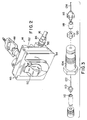
- each vacuum regulator 14 each include a housing 46 clampingly mounted to respective ones of the gas cylinders by a yoke clamp or bracket assembly 48.
- the bracket assembly 48 for mounting the regulators 14 to the gas cylinders is conventional and will not be described in detail.
- Each vacuum regulator 14 also includes a control knob/indicator 50 which is positionable as shown in Fig. 11 in an "off" position preventing flow of gas through the regulator 14.
- the control knob 50 can be manually rotated counterclockwise 180° from the "off" position shown in Fig. 11 to a "standby" position shown in Fig. 2 and Fig. 5.
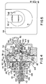
- the vacuum regulator includes a front housing 52 supporting a front cover 54.
- the cover 54 in turn supports the control knob 50 for vertical slidable movement between the "standby", “on” and “empty” positions and also for rotation of the control knob 50 to the "off" position.
- the vacuum regulator 14 also includes a rear housing 56 fixed to the rear face 58 of the front housing 52.
- a flexible diaphragm 60 has a periphery 62 clamped between the front 52 and rear 56 housing.
- the diaphragm includes a central opening housing a diaphragm backing plate assembly 64 comprised of a diaphragm backing plate 66 and a diaphragm backing plate nut 68 which clampingly engages the inner portion 70 of the diaphragm 60 therebetween.
- the diaphragm backing plate assembly 64 is housed in the chamber 72 defined by the rear housing 56, and the diaphragm backing plate assembly 64 is movable with the diaphragm in the chamber 72 between the positions shown in Figs. 4, 6, 8 and 10.
- the backing plate nut 68 is threaded onto a projecting threaded extension 74 of the backing plate 66 such that the backing plate nut 68 clampingly engages the diaphragm 60 and clamps it against the backing plate 66 in fluid tight relation.
- the diaphragm backing plate 66 includes a circular groove 76 in its front face 78, the groove 76 housing a projecting circular flange 80 of the front housing 52 such that the diaphragm backing plate assembly 64 is supported for movement in the chamber 72 of the rear housing 56 toward and away from the front housing 52.
- the vacuum tubing 16 communicates with the chamber 72 through a port 82, and a coupling 84 (Fig. 2) connects the tubing to the rear housing 56.
- the vacuum in the tubing 16 thus draws a vacuum in the chamber 72 defined by the rear housing 56.
- the front face of the diaphragm 60 is subjected to atmospheric pressure in the space 86 between the front housing 52 and the diaphragm 60 and diaphragm backing plate 66.
- atmospheric pressure on the diaphragm 60 and diaphragm backing plate 66 will tend to force the diaphragm backing plate assembly 64 rearwardly into the rear housing 56.
- the vacuum regulator 14 also includes a valve assembly 90 fixed to the rear housing 56 and controlling flow of chlorine gas from the gas cylinder through the inlet port 92 and into the vacuum chamber 72 where it can then be drawn through the port 82 to the vacuum line or tubing 16.
- the valve assembly 90 includes a secondary valve housing 94 having one end housed in a bore 96 in a sleeve 98 projecting rearwardly from the rear housing 56.
- a valve housing retainer nut 100 is provided to secure the secondary valve housing 94 to the sleeve 98 and rear housing 56.
- the secondary valve housing 94 includes a central bore 102 housing a regulator nipple 104 which is threaded into the secondary valve housing 94.
- the regulator nipple 104 includes a central bore 106 housing a valve seat 108 and a valve body 110 biased against the valve seat 108 by a first compression spring 112.
- the secondary valve housing 94 also houses a secondary valve seat 114 and a secondary valve body 116 biased against that valve seat by a second compression spring 118.
- the second compression spring 118 is supported by a stop member 120 slidably housed in the bore 102 in the secondary valve housing 94.
- a rod 122 connected to the first valve body engages the stop 120 to provide a connection between the stop 120 and the first valve body 110.
- a second rod 124 extends from the secondary valve body 116 and projects forwardly into the vacuum chamber 72 provided by the rear housing.
- the regulator nipple 104 also includes the inlet port 92 which communicates through the clamping bracket to the gas cylinder 12.
- the regulator also includes an operating pin or shaft 130 threaded into a central bore 132 of the diaphragm backing plate 66 and located centrally with respect to the diaphragm 60.
- the operating pin 130 has an end 134 adapted to move with the diaphragm backing plate assembly 64 and to selectively engage the end of the rod 124 extending from the secondary valve body 116 and to provide for movement of the secondary valve body 116 away from the secondary valve seat 114.
- the operating pin 135 is threaded into the diaphragm backing plate 66 such that it moves with the diaphragm backing plate 66 in the direction of its longitudinal axis.
- the threads 136 connecting between the operating pin 130 and the diaphragm backing plate assembly 64 permits the operating pin 130 to be rotated 180° to an "off" position as shown in Fig. 10 where it is backed out of the diaphragm backing plate 66 such that it cannot engage the rod 124 extending from the secondary valve body 116.
- the opposite end of the operating pin 130 includes a cavity or bore 138 housing an operating lever pawl 140 and a compression spring 142.
- the operating lever pawl 140 is connected to the operating pin 130 by a cross pin 144 and is supported by the operating pin 130 such that the pawl 140 is resiliently biased by the compression spring 142 into engagement with cam surfaces 142 provided in a recess 144 in the end of a lever 146.
- the cross pin 144 connecting the operating lever pawl 140 to the end of the operating pin 130 also pivotally connects the lever 146 to the operating pin 130.
- the chlorine gas cylinder 12 will then continue to supply gas to the injector 18 until the cylinder 12 is completely empty.
- the vacuum in the vacuum chamber 72 will increase causing the diaphragm 60 and the diaphragm backing plate assembly 64 to move from the position shown in Fig. 6 to the position shown in Fig. 8.
- the diaphragm backing plate assembly 64 moves to this position, the operating pin 130 and operating lever pawl are moved to the cam position shown Fig. 8 and the operating lever 50 will be caused to move by the operating lever pawl 140 and the cam surface 154 of the operating lever to the "empty" position shown in Figs. 8 and 9.
- One of the principle features of the invention is the construction of the vacuum regulator to provide both a primary and a secondary backup check valve 110 and 116 operated by a single diaphragm 60. In the event one of the check valves fails to close fully, the other check valve will insure complete sealing of the valve assembly. But, while a second check valve 116 can be provided, the construction of the regulator of the invention facilitates the use of only a single diaphragm 60 to provide for movement of both valve assemblies.
- the vacuum regulator also includes a pressure relief valve 160 for discharging gas from the regulator in the event that a gas pressure develops in the vacuum chamber 72.
- a gas discharge port 162 in the rear housing 56 communicates through a spring biased check valve with a discharge port 166.
- the check valve includes a flexible diaphragm 164 biased against the port 162 by a pin 168 and a compression spring 170.
- the compression spring 170 is backed by a plug 172 threaded into a bore 174 provided in the rear housing.
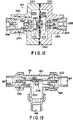
- the remote switchover valve 38 is illustrated in greater detail in Figs. 13-15 and includes a T-shaped valve body 180 including a pair of inlets 182 and 184 connected to the tubing 30 extending from the banks of chlorine tanks and an outlet port 186 connected by tubing 32 to the rotameter 34 and injector 18.
- the remote switchover device 38 includes a reciprocally movable elongated valve member 190 having opposite ends, the opposite ends of the elongated valve member supporting resilient valve cups 192 and 194.
- the elongated valve member is movable from the intermediate position shown in Fig. 13 to a position wherein the resilient valve cup 192 at one end of the elongated member 190 is engageable with a seat surface 196 to selectively prevent gas flow through the inlet 182.
- the elongated valve member 190 is also movable from the intermediate position to the right as shown in Fig. 13 to a position wherein the resilient valve cup 194 sealingly engages a second seat surface 198 to selectively prevent gas flow through the inlet 184.
- a pair of compression springs 200 and 202 are provided for biasing the elongated valve member 190 toward the centered or intermediate position shown in Fig. 13.
- a detent device is also provided for releasably restraining the elongated valve member 190 in a selected position where the valve member 192 seats against the seat 196 or alternatively for releasably restraining the elongated valve member 190 in a second position wherein the valve member 194 seats against the opposite seat 198 at the opposite end of the valve.
- the detent device includes a rack 204 formed integrally with the central portion of the elongated valve member 190 and a pinion 206 engaging the rack 204.
- the pinion 206 is mounted on the end of a manually rotatable shaft 208 (Fig. 15), and a control knob 210 is mounted on the opposite end of the rotatable shaft 208.
- the control knob 210 can be manually rotated between a first position wherein the elongated valve member 190 is moved to a position where the cup valve 192 engages the valve seat 196. In that position (Fig. 14) a spring biased detent ball 214 engages a notch 216 provided in a collar 218 mounted on the shaft 208. The detent ball 214 releasably holds the elongated valve member 190 in that position.
- the manual control knob 210 can be rotated in the opposite direction wherein a second spring biased detent ball 220 will engage the notch 216 in the collar 218 to hold the elongated valve member 190 in a position wherein the cup valve 194 engages the other valve seat 198.
- control knob 210 can be rotated to a position wherein the detent ball 214 will hold the elongated valve member 190 in a position wherein one of the cup valves engages a valve seat to block the flow of gas through that inlet 182.
- the elongated valve member is held in that position by the force of the detent 214 and by the pressure of gas at inlet 184 from the other bank of cylinders.
- Fig. 12 illustrates in greater detail the even drawdown device 44 which includes a pair of housing portions 230 and 232 defining chambers 234 and 236 separated by a diaphragm 238.
- the periphery of the diaphragm 238 is clamped between the halves 230 and 232 of the housing and an O-ring 240 provides a fluid tight seal.
- the left housing portion 230 shown in Fig. 12 includes a boss or sleeve 242 threadably housing a valve seat holder 244.
- a Teflon valve seat 246 is housed in the valve seat holder 244 and a reducing bushing 248 provides for connection of the tubing 16 with bore 249.
- the right housing portion 232 includes a boss or sleeve 250 housing a valve seat 252, and a reducing bushing 254 is provided for connecting the other tubing 16 to the inlet bore 256.
- the even drawdown device 44 further includes a valve spool 260 having a diaphragm hub 262 clampingly engaging the central portion of the diaphragm 238 such that the valve spool 260 is movable with the diaphragm.
- One end of the valve spool 260 includes a valve body 264 selectively engageable with the valve seat 246 and the opposite end of the valve spool 260 includes a second valve body 266 engageable with the second valve seat 252.
- the second valve seat 252 includes a plurality of small orifices 268 between the valve body 266 and the valve seat 252 to permit controlled gas flow past the valve seat 252 when the valve member 266 engages the valve seat 252.
- the left and right housing portions 230 and 232 are provided with discharge ports 270 and 272, respectively which communicate with the tube 30 providing flow of gas to the rotameter and the injector 18.
- vacuum in the tube 30 communicating with rotameter 34 applies a vacuum in the chambers 234 and 236 on both sides of the diaphragm 238, causing gas to be drawn initially through the orifices 268 around the valve body 266.
- the pressure differential caused by gas flow into the right chamber 236 as seen in Fig. 12 will create a pressure on the diaphragm 238 causing movement of the valve body 264 away from the valve seat 246 to cause flow of gas into the chamber 234 and until the gas pressure in the chambers on 234 and 236 opposite sides of the diaphragm 238 is equal.
- the gas flow from the tubes 16 communicating with the two gas cylinders 12 will thus be equalized to provide for uniform and even flow from those cylinders 12 to the injector 18.
Landscapes
- Engineering & Computer Science (AREA)
- General Engineering & Computer Science (AREA)
- Mechanical Engineering (AREA)
- Water Supply & Treatment (AREA)
- Hydrology & Water Resources (AREA)
- Environmental & Geological Engineering (AREA)
- Life Sciences & Earth Sciences (AREA)
- Chemical & Material Sciences (AREA)
- Organic Chemistry (AREA)
- Filling Or Discharging Of Gas Storage Vessels (AREA)
- Feeding, Discharge, Calcimining, Fusing, And Gas-Generation Devices (AREA)
- Fluid-Driven Valves (AREA)
- Treatment Of Water By Oxidation Or Reduction (AREA)
- Organic Low-Molecular-Weight Compounds And Preparation Thereof (AREA)
Abstract
Description
- The invention relates to low capacity gas feed systems of the type for use in feeding chlorine gas to a water supply to chlorinate the water. More specifically the invention relates to gas flow regulators for controlling the flow of gas from gas cylinders and valves for controlling gas flow from one gas supply to another gas supply.
- Low capacity chlorine gas feed systems provide for the supply of gas from chlorine gas containers through a gas pressure regulator device to an injector wherein the chlorine gas is delivered to a water supply conduit. One prior art chlorine feed system is illustrated in the assignee's Technical Data Sheet 910.250 titled "SONIX 100™ Chlorinator." Attention is also directed to the U.S. Konkling Patent 3,779,268 illustrating a prior art regulator valve for a chlorine gas system.
- One limitation of prior art chlorine gas supply systems is the amount of chlorine which can be delivered to the water supply. Use of a single gas cylinder permits the discharge of chlorine gas only at a limited flow rate before frosting of the valve makes the gas regulator valve inoperative.
- In many areas, chlorine gas suppliers require that chlorine tanks be emptied completely before they can be returned to the supplier for refilling. Prior art gas regulation systems have not provided an effective mechanism for insuring efficient use of all of the chlorine in the tanks. In other areas, chlorine gas suppliers require that chlorine tanks returned for refilling contain a predetermined quantity of chlorine in the tanks. Prior art gas regulation systems do not provide an effective mechanism for controlling the amount of gas left in the gas supply cylinders.
- Another limitation of prior art chlorine gas systems is that they have not provided an effective and efficient system for switching over from one chlorine supply container to another chlorine supply container once the supply in the first container is exhausted.
- Another limitation of prior art gas feed systems including an arrangement for switching from one gas supply cylinder to another cylinder is that they do not insure complete use or controlled use of the gas in the first container.
- Another disadvantage of prior art gas supply systems is that they require mechanically complex regulator valve assemblies and are expensive to manufacture and can be unreliable.
- US3779268 discloses an automatic changeover diaphragm valve for chlorine gas service that incorporates a loading spring on the atmospheric side of the diaphragm in order to provide a regulated positive pressure discharge. A latching mechanism for the valve employs spaced parallel rods which engage a V-groove on the loading spring spool to hold the valve in standby condition prior to release for changeover operation. The diaphragm includes a tetrafluorethylene web on the gas side and a chlorosulfonated web on the atmospheric side clamped at the outer peripheries. A sectored metal disk is used to abut against the chlorosulfonated web while the central portions of the two webs are in clamped disposition.
- US3592215, considered as closest prior art, according to the preamble of claim 1, discloses an automatic changeover valve assembly for controlling the selective withdrawal of fluid from either one of two cylinders or containers, one serving as the main supply and the other as a standby or reserve source. The valve assembly comprises a Belleville spring supporting a double-ended valve plug within a demand chamber communicating with a demand line. The first plug cooperates with a valve seat mounted on a diaphragm enclosing a first fluid chamber communicating with a supply fluid source, and the second plug cooperates with a valve seat mounted on a diaphragm enclosing a second chamber communicating with a reserve source.
- DE 2012702 discloses a system with two pressurized gas cylinders each having a pressure- reducing and shut-off valve unit, supplying a flow rate control unit. When the gas pressure in the system falls below a predetermined level the valve unit associated with the gas cylinder in use shuts off automatically and the other opens.
- In accordance with the present invention there is provided a gas feed system for supplying a gas to a water supply from a gas supply including at least two gas sources comprising: a switchover device (38) including a first shiftable valve member (192) arranged to selectively isolate a first inlet (182), connected to a second shiftable valve member (194) arranged to selectively isolate a second inlet (184); a first gas source (40) in communication with the switchover device (38) via the first inlet (182); a second gas source (42) in communication with the switchover device (38) via the second inlet (184); an injector (18) in communication with the water supply (20), the injector connected to the switchover device via an outlet (186); and wherein the switchover device (38) selectively supplies the gas to the injector (18), characterized in that the first shiftable valve member (192) is connected to a second shiftable valve member (194) via a reciprocally movable valve member (190) movable between a first position in which the second gas source (42) is selectively isolated, a second position in which the first gas source (40) is selectively isolated, and a third position in which gas is supplied from both the first gas source (40) and the second gas source (42) simultaneously.
- The present invention provides a gas feed system for supplying a gas, and can be used to supply gas such as chlorine to a water system for chlorinating the water. The gas feed system may include a pair of gas containers or multiple banks of containers and provides for automatic switch over from one container or a bank of containers to a second container or bank of containers once the first container or bank of containers is empty and such that the first containers can be completely emptied. The gas feed system of the invention may also provide for automatic switch over from one bank of containers to a second bank of containers while providing for complete emptying of the first bank of containers.
- The gas feed system of the invention, preferably, facilitates the use of two sets or banks of multiple tanks of gas. When used to supply chlorine to a water system, the gas supply system can have one bank of tanks supplying chlorine to an injector while the other bank of tanks can remain in a standby condition and such that the second bank of tanks will automatically supply chlorine to the water supply when the amount of gas in the first bank of tanks falls below a predetermined level. Additionally, the tanks in each bank of tanks may discharge even quantities of gas. Gas discharged from a single tank can be limited by frosting that occurs in the control valves. The provision of multiple tanks in parallel permits the discharge of sufficient amounts of gas, and the provision of an even draw-down device embodied in the invention provides for uniform simultaneous discharge from a pair of gas tanks or cylinders.
- A gas feed regulator may be provided for controlling the supply of gas from a container such as a chlorine cylinder, the regulator having a simplified construction. The gas feed regulator includes a retractable center pin extending through the center of a pressure responsive diaphragm, the center pin being movable to provide for manual shutoff of the regulator to interrupt gas flow from the gas supply. The regulator includes a manual control lever connected to the center pin, the lever being rotatable 180° to manually shut off the valve.
- The gas feed regulator may further include the provision of a manual control/operation indicator switch mounted on the regulator housing and engaging the operating lever, the switch being rotatable to rotate the operating lever and the center pin between a manual "off" and a "stand-by" operating position. The indicator switch further cooperates with the operating lever to form a detent assembly. The detent assembly holds the center pin in a stand-by position until a differential pressure caused by vacuum on the diaphragm causes the center pin to move to an "on" or operating position wherein gas can flow through the regulator from the gas container. When the container is exhausted of gas, the vacuum on the regulator diaphragm will move the center pin to a position where the detent assembly and indicator switch move to an "empty" position. The indicator switch can be rotated manually to an "off' position where the gas flow through the regulator is manually interrupted. The vacuum regulator further includes a primary check valve operated by the central pin and the vacuum operated diaphragm and further includes a secondary pressure check valve also operated by the center pin and diaphragm.
- One of the advantages of the vacuum regulator included in the gas supply system is that the vacuum regulator has an efficient construction, has a minimum number of components and can be economically assembled and manufactured.
- The gas feed system further includes a remote automatic switchover device connected to two gas containers or two banks of gas containers and providing for switch over from one container or bank of containers to the other container or bank of containers when the first empties. The remote automatic switchover device includes a valve housing and a chamber, two inlets communicating with respective ones of the banks of gas cylinders and an outlet communicating with a gas injector supplying gas to a water source. A double acting spool is housed in the chamber and selectively closes one or the other inlet. A manually operable arm connected to the double acting spool is movable between a position opening one outlet and a detent is provided for maintaining the spool in that position until gas pressure supplied through the one inlet decreases to a pressure wherein pressure supplied from the other inlet on the spool member overcomes the detent and opens the other inlet leaving the spool member in a position where both inlets are open.
- The gas feed system further includes at least one even drawdown device operably connected to two gas cylinders and connecting the regulators of those two cylinders to the remote switchover device. The even drawdown device provides for even flow of gas from the two gas cylinders connected to the even drawdown device.
- One of the principal features is the provision in the vacuum regulator of a diaphragm assembly including a diaphragm made of Teflon sheet, the Teflon sheet being heat formed to include concentric grooves. A concentric groove at the periphery of the diaphragm is housed in a groove provided in the opposed two halves in the regulator body and secured in place by an O-ring seal. A concentric groove in the central portion of the diaphragm is similarly clamped using an O-ring between a central diaphragm backing plate and an opposed backing plate nut. The construction of the heat formed diaphragm and O-ring seals permits the use of fewer mechanical components to secure the diaphragm and the use of lower clamping pressures on the diaphragm while also providing a reliable long lasting diaphragm configuration. The diaphragm arrangement is an improvement over prior art constructions where heat can cause variations in the thickness of the diaphragm membrane and loosening of clamping screws. This permits the membrane to pull away from the supporting structure causing wrinkling of the membrane and permitting air leakage into the vacuum regulator.
-
- Fig. 1 is a schematic illustration of a gas supply system embodying the invention.
- Fig. 2 is a perspective view of a vacuum regulator and cylinder mounting bracket included in the gas feed system shown in Fig. 1.
- Fig. 3 is an exploded perspective view of a gas flow control valve assembly included in the vacuum regulator shown in Fig. 2.
- Fig. 4 is an enlarged cross section view of a vacuum regulator included in the gas feed system shown in Fig. 1 and showing the vacuum regulator in a "standby" position.
- Fig. 5 is a side view of the vacuum regulator shown in Fig. 4.
- Fig. 6 is a view similar to Fig. 4 and illustrating the vacuum regulator in an "on" position.
- Fig. 7 is a view similar to Fig. 7 and showing the vacuum regulator in the "on" position.
- Fig. 8 is a view similar to Figs. 4 and 6 and showing the vacuum regulator in an "empty" position.
- Fig. 9 is a view similar to Figs. 5 and 7 and showing the vacuum regulator in an "empty" position.
- Fig. 10 is a view similar to Fig. 4 and showing the vacuum regulator in an "off" position.
- Fig. 11 is a view similar to Fig. 5 and showing the vacuum regulator in the "off" position.
- Fig. 12 is an enlarged cross section view of an even drawdown valve included in the gas supply system shown in Fig. 1.
- Fig. 13 is an enlarged cross section view of a remote switchover valve included in the gas supply system shown in Fig. 1.
- Fig. 14 is a side view of the remote switchover device shown in Fig. 13.
- Fig. 15 is a cross section taken along line 15-15 in Fig. 14.
- Fig. 16 is an enlarged cross section view of a gas injector included in the gas supply system shown in Fig. 1.
- Fig. 1 illustrates a gas feed system embodying the invention and including a plurality of
gas cylinders 12. In the illustrated arrangement thegas cylinders 12 are conventional chlorine gas containers. Thegas feed system 10 further includes avacuum regulator 14 mounted on eachcylinder 12, each of thevacuum regulators 14 comprising a vacuum operated valve intended to control the supply of chlorine gas from thegas cylinders 12. The vacuum regulators 14 are connected through plastic tubing orconduits 16 to supply chlorine gas to achlorine gas injector 18. Thechlorine gas injector 18 is best shown in Fig. 16 and has a conventional construction. Thegas injector 18 provides for mixing of gas into water flowing through awater supply conduit 20 and facilitates the injection of chlorine gas into the water supply. At theinjector 18, meteredgas entering port 22 is dissolved atchamber 23 in the water stream flowing throughpassage 24 from thewater supply conduit 20. The resultant solution is discharged throughpassage 26 to the point of application and the flow of water through theinjector 18 generates a vacuum atport 22 and in the tubing orconduit 28. It is this vacuum in thetubing 28 which draws gas through theconduits injector 18 and which operates thevacuum regulators 14 connected to thecylinders 12. - In the illustrated arrangement of the gas feed system, a
rotameter 34 is provided between thegas feed cylinders 12 and theinjector 18. Therotameter 34 indicates the volume or rate of the flow of gas through thetubing injector 18. Therotameter 34 can also include acontrol valve 36 for controlling the rate of flow through thetubing injector 18. The construction of therotameter 34 and thecontrol valve 36 is conventional and will not be described in detail. While in the illustrated arrangement therotameter 34 is mounted remote from thevacuum regulators 14, in other arrangements arotameter 34 could be mounted directly on each vacuum regulator to indicate the flow of gas from theindividual gas cylinders 12 to thetubing 16. - The
gas supply system 10 shown in Fig. 1 further includes aremote switchover device 38 for providing for supply of chlorine gas from afirst bank 40 of cylinders during initial operation of the chlorine gas system while maintaining asecond bank 42 of cylinders in a standby condition. Theremote switchover device 38 includes a valve which isolates thesecond bank 42 of cylinders during initial operation of the cylinders and then, when the gas in thefirst bank 40 of cylinders nears an empty condition, theremote switchover device 38 opens to provide for supply of gas from thesecond bank 42 of cylinders to theinjector 18 while also maintaining thefirst bank 40 of cylinders in communication with theinjector 18 so that all of the gas in thefirst bank 40 of cylinders can be used. - The
remote switchover device 38 can then be manually switched over to connect only thesecond bank 42 of cylinders to theinjector 18 and to isolate thefirst bank 40 of cylinders. Thecylinders 12 in thefirst bank 40 can then be removed from the system for refilling and be replaced with full gas containers. Theremote switchover device 38 can then maintain thosecontainers 12 in the standby condition until thesecond bank 42 of cylinders nears an empty condition. - In the
gas supply system 10 illustrated in Fig. 1, each bank ofcylinders even drawdown device 44 connecting the twovacuum regulators 14 in that bank of cylinders to thetubing 30 communicating with theremote switchover device 38 and theinjector 18. Theeven drawdown device 44 provides for simultaneously even or equal flow of gas from the twocylinders 12 in the bank ofcylinders 40 to theremote switchover device 38. - Referring more particularly to the vacuum regulators, they each include a
housing 46 clampingly mounted to respective ones of the gas cylinders by a yoke clamp orbracket assembly 48. Thebracket assembly 48 for mounting theregulators 14 to the gas cylinders is conventional and will not be described in detail. Eachvacuum regulator 14 also includes a control knob/indicator 50 which is positionable as shown in Fig. 11 in an "off" position preventing flow of gas through theregulator 14. Thecontrol knob 50 can be manually rotated counterclockwise 180° from the "off" position shown in Fig. 11 to a "standby" position shown in Fig. 2 and Fig. 5. As will be explained below, when thecontrol knob 50 of thevacuum regulator 14 is in the "standby" position, the regulator valve is closed until vacuum in thetubing 16 actuates the regulator valve to cause thecontrol knob 50 to move downwardly to the "on" position shown in Fig. 7 and wherein the regulator valve will then permit discharge of chlorine gas in response to vacuum in thetubing 16. When thecylinder 12 connected to thatregulator 14 is empty of gas, vacuum in thetubing 16 will then actuate the regulator to cause the control knob to move to the "empty" position shown in Fig. 9 to thereby indicate depletion of the gas in thechlorine cylinder 12. The operator can then manually rotate the control knob to the "off" position of Fig. 11, and thecylinder 12 can then be disconnected from theregulator 14 and then replaced with a full cylinder. - Referring now more specifically to the construction of the
vacuum regulator 14, as seen in Fig. 4, the vacuum regulator includes afront housing 52 supporting afront cover 54. Thecover 54 in turn supports thecontrol knob 50 for vertical slidable movement between the "standby", "on" and "empty" positions and also for rotation of thecontrol knob 50 to the "off" position. - The
vacuum regulator 14 also includes arear housing 56 fixed to therear face 58 of thefront housing 52. Aflexible diaphragm 60 has aperiphery 62 clamped between the front 52 and rear 56 housing. The diaphragm includes a central opening housing a diaphragmbacking plate assembly 64 comprised of adiaphragm backing plate 66 and a diaphragmbacking plate nut 68 which clampingly engages theinner portion 70 of thediaphragm 60 therebetween. The diaphragmbacking plate assembly 64 is housed in thechamber 72 defined by therear housing 56, and the diaphragm backingplate assembly 64 is movable with the diaphragm in thechamber 72 between the positions shown in Figs. 4, 6, 8 and 10. Thebacking plate nut 68 is threaded onto a projecting threaded extension 74 of thebacking plate 66 such that thebacking plate nut 68 clampingly engages thediaphragm 60 and clamps it against thebacking plate 66 in fluid tight relation. - The
diaphragm backing plate 66 includes a circular groove 76 in itsfront face 78, the groove 76 housing a projecting circular flange 80 of thefront housing 52 such that the diaphragm backingplate assembly 64 is supported for movement in thechamber 72 of therear housing 56 toward and away from thefront housing 52. - The
vacuum tubing 16 communicates with thechamber 72 through aport 82, and a coupling 84 (Fig. 2) connects the tubing to therear housing 56. The vacuum in thetubing 16 thus draws a vacuum in thechamber 72 defined by therear housing 56. The front face of thediaphragm 60 is subjected to atmospheric pressure in the space 86 between thefront housing 52 and thediaphragm 60 anddiaphragm backing plate 66. When vacuum is applied in thechamber 72 defined by therear housing 56, atmospheric pressure on thediaphragm 60 anddiaphragm backing plate 66 will tend to force the diaphragm backingplate assembly 64 rearwardly into therear housing 56. - The
vacuum regulator 14 also includes avalve assembly 90 fixed to therear housing 56 and controlling flow of chlorine gas from the gas cylinder through theinlet port 92 and into thevacuum chamber 72 where it can then be drawn through theport 82 to the vacuum line ortubing 16. - The
valve assembly 90 includes asecondary valve housing 94 having one end housed in abore 96 in asleeve 98 projecting rearwardly from therear housing 56. A valvehousing retainer nut 100 is provided to secure thesecondary valve housing 94 to thesleeve 98 andrear housing 56. Thesecondary valve housing 94 includes acentral bore 102 housing aregulator nipple 104 which is threaded into thesecondary valve housing 94. Theregulator nipple 104 includes acentral bore 106 housing avalve seat 108 and avalve body 110 biased against thevalve seat 108 by afirst compression spring 112. Thesecondary valve housing 94 also houses asecondary valve seat 114 and asecondary valve body 116 biased against that valve seat by asecond compression spring 118. Thesecond compression spring 118 is supported by astop member 120 slidably housed in thebore 102 in thesecondary valve housing 94. Arod 122 connected to the first valve body engages thestop 120 to provide a connection between thestop 120 and thefirst valve body 110. Asecond rod 124 extends from thesecondary valve body 116 and projects forwardly into thevacuum chamber 72 provided by the rear housing. Theregulator nipple 104 also includes theinlet port 92 which communicates through the clamping bracket to thegas cylinder 12. - The regulator also includes an operating pin or
shaft 130 threaded into acentral bore 132 of thediaphragm backing plate 66 and located centrally with respect to thediaphragm 60. Theoperating pin 130 has anend 134 adapted to move with the diaphragm backingplate assembly 64 and to selectively engage the end of therod 124 extending from thesecondary valve body 116 and to provide for movement of thesecondary valve body 116 away from thesecondary valve seat 114. The operating pin 135 is threaded into thediaphragm backing plate 66 such that it moves with thediaphragm backing plate 66 in the direction of its longitudinal axis. The threads 136 connecting between the operatingpin 130 and the diaphragm backingplate assembly 64 permits theoperating pin 130 to be rotated 180° to an "off" position as shown in Fig. 10 where it is backed out of thediaphragm backing plate 66 such that it cannot engage therod 124 extending from thesecondary valve body 116. - The opposite end of the
operating pin 130 includes a cavity or bore 138 housing an operatinglever pawl 140 and acompression spring 142. The operatinglever pawl 140 is connected to theoperating pin 130 by across pin 144 and is supported by theoperating pin 130 such that thepawl 140 is resiliently biased by thecompression spring 142 into engagement withcam surfaces 142 provided in arecess 144 in the end of alever 146. Thecross pin 144 connecting the operatinglever pawl 140 to the end of theoperating pin 130 also pivotally connects thelever 146 to theoperating pin 130. - In operation of the
vacuum regulator 14, when the operatinglever 50 is in the "standby" position shown in Figs. 4 and 5, and when there is no vacuum applied through the port to thevacuum chamber 72, the components of thevacuum regulator 14 will assume the position illustrated in Fig. 4, with both thefirst valve body 110 andsecond valve body 116 in engagement with therespective valve seats inlet port 92 into thevacuum chamber 72. - When the
remote switchover valve 38 actuates to cause vacuum to be drawn in thevacuum tubing 16 and thevacuum chamber 72, vacuum in thevacuum chamber 72 will cause thediaphragm 60 and the diaphragm backingplate assembly 64 to move to the position shown in Fig. 6. Theoperating pin 130 is carried by the diaphragm backingplate assembly 64 and such that theend 134 of theoperating pin 130 will engage therod 124 projecting from thesecondary valve body 116. This movement of theoperating pin 130 opens both thesecondary valve 116 and thefirst valve body 110 to provide for flow of gas through theinlet port 92 into thevacuum chamber 72 where it will be drawn by vacuum in thetubing 16 through theport 82. - As the opposite end of the
operating pin 130 moves to the left as seen in Figs. 4 and 6, the end of the operatinglever pawl 140 will move with respect to thelever 146 from engagement with thecam surface 150 shown in Fig. 4 to engagement with thecam surface 152 shown in Fig. 6 thereby causing the operatinglever 50 to be moved from the "standby" position shown in Fig. 5 to the "on" position shown in Fig. 7. - The
chlorine gas cylinder 12 will then continue to supply gas to theinjector 18 until thecylinder 12 is completely empty. When thecylinder 12 is empty, the vacuum in thevacuum chamber 72 will increase causing thediaphragm 60 and the diaphragm backingplate assembly 64 to move from the position shown in Fig. 6 to the position shown in Fig. 8. When the diaphragm backingplate assembly 64 moves to this position, theoperating pin 130 and operating lever pawl are moved to the cam position shown Fig. 8 and the operatinglever 50 will be caused to move by the operatinglever pawl 140 and thecam surface 154 of the operating lever to the "empty" position shown in Figs. 8 and 9. - The operator can then rotate the operating
lever 180° from the "empty" position shown in Fig. 9 to the "off" position shown in Fig. 11. Rotation of the operatinglever 50 to the "off" position causes rotation of theoperating pin 130 with respect to thediaphragm backing plate 66 and threadably backs theoperating pin 130 out of thediaphragm backing plate 66 thereby pulling theend 134 of theoperating pin 130 away from therod 124 connected to thesecondary valve body 116. As shown in Fig. 10, thecheck valves - One of the principle features of the invention is the construction of the vacuum regulator to provide both a primary and a secondary
backup check valve single diaphragm 60. In the event one of the check valves fails to close fully, the other check valve will insure complete sealing of the valve assembly. But, while asecond check valve 116 can be provided, the construction of the regulator of the invention facilitates the use of only asingle diaphragm 60 to provide for movement of both valve assemblies. - The vacuum regulator also includes a
pressure relief valve 160 for discharging gas from the regulator in the event that a gas pressure develops in thevacuum chamber 72. Agas discharge port 162 in therear housing 56 communicates through a spring biased check valve with adischarge port 166. The check valve includes aflexible diaphragm 164 biased against theport 162 by apin 168 and acompression spring 170. Thecompression spring 170 is backed by aplug 172 threaded into abore 174 provided in the rear housing. - The
remote switchover valve 38 is illustrated in greater detail in Figs. 13-15 and includes a T-shapedvalve body 180 including a pair ofinlets 182 and 184 connected to thetubing 30 extending from the banks of chlorine tanks and anoutlet port 186 connected bytubing 32 to therotameter 34 andinjector 18. Theremote switchover device 38 includes a reciprocally movableelongated valve member 190 having opposite ends, the opposite ends of the elongated valve member supporting resilient valve cups 192 and 194. The elongated valve member is movable from the intermediate position shown in Fig. 13 to a position wherein theresilient valve cup 192 at one end of theelongated member 190 is engageable with aseat surface 196 to selectively prevent gas flow through the inlet 182. Theelongated valve member 190 is also movable from the intermediate position to the right as shown in Fig. 13 to a position wherein theresilient valve cup 194 sealingly engages asecond seat surface 198 to selectively prevent gas flow through theinlet 184. - A pair of compression springs 200 and 202 are provided for biasing the
elongated valve member 190 toward the centered or intermediate position shown in Fig. 13. - A detent device is also provided for releasably restraining the
elongated valve member 190 in a selected position where thevalve member 192 seats against theseat 196 or alternatively for releasably restraining theelongated valve member 190 in a second position wherein thevalve member 194 seats against theopposite seat 198 at the opposite end of the valve. The detent device includes arack 204 formed integrally with the central portion of theelongated valve member 190 and apinion 206 engaging therack 204. Thepinion 206 is mounted on the end of a manually rotatable shaft 208 (Fig. 15), and a control knob 210 is mounted on the opposite end of therotatable shaft 208. The control knob 210 can be manually rotated between a first position wherein theelongated valve member 190 is moved to a position where thecup valve 192 engages thevalve seat 196. In that position (Fig. 14) a spring biaseddetent ball 214 engages anotch 216 provided in acollar 218 mounted on theshaft 208. Thedetent ball 214 releasably holds theelongated valve member 190 in that position. The manual control knob 210 can be rotated in the opposite direction wherein a second spring biaseddetent ball 220 will engage thenotch 216 in thecollar 218 to hold theelongated valve member 190 in a position wherein thecup valve 194 engages theother valve seat 198. - In operation of the remote switchover device, the control knob 210 can be rotated to a position wherein the
detent ball 214 will hold theelongated valve member 190 in a position wherein one of the cup valves engages a valve seat to block the flow of gas through that inlet 182. The elongated valve member is held in that position by the force of thedetent 214 and by the pressure of gas atinlet 184 from the other bank of cylinders. When the gas pressure atinlet 184 from the other bank of cylinders falls below a predetermined level, gas pressure from the other bank of cylinders and the force of thereturn spring 200 will overcome the force of thedetent ball 214 and theelongated valve member 190 will be shifted by the compression springs 200 and 202 to a central position. In this position chlorine gas can then be drawn from the second bank of cylinders while the first bank of cylinders is also connected to the vacuum tubing and theinjector 18. - Fig. 12 illustrates in greater detail the
even drawdown device 44 which includes a pair ofhousing portions chambers 234 and 236 separated by adiaphragm 238. The periphery of thediaphragm 238 is clamped between thehalves ring 240 provides a fluid tight seal. Theleft housing portion 230 shown in Fig. 12 includes a boss orsleeve 242 threadably housing avalve seat holder 244. ATeflon valve seat 246 is housed in thevalve seat holder 244 and a reducingbushing 248 provides for connection of thetubing 16 withbore 249. Theright housing portion 232 includes a boss orsleeve 250 housing avalve seat 252, and a reducingbushing 254 is provided for connecting theother tubing 16 to the inlet bore 256. - The
even drawdown device 44 further includes avalve spool 260 having a diaphragm hub 262 clampingly engaging the central portion of thediaphragm 238 such that thevalve spool 260 is movable with the diaphragm. One end of thevalve spool 260 includes avalve body 264 selectively engageable with thevalve seat 246 and the opposite end of thevalve spool 260 includes asecond valve body 266 engageable with thesecond valve seat 252. Thesecond valve seat 252 includes a plurality of small orifices 268 between thevalve body 266 and thevalve seat 252 to permit controlled gas flow past thevalve seat 252 when thevalve member 266 engages thevalve seat 252. The left andright housing portions discharge ports tube 30 providing flow of gas to the rotameter and theinjector 18. - In operation of the even drawdown device, vacuum in the
tube 30 communicating withrotameter 34 applies a vacuum in thechambers 234 and 236 on both sides of thediaphragm 238, causing gas to be drawn initially through the orifices 268 around thevalve body 266. The pressure differential caused by gas flow into the right chamber 236 as seen in Fig. 12 will create a pressure on thediaphragm 238 causing movement of thevalve body 264 away from thevalve seat 246 to cause flow of gas into thechamber 234 and until the gas pressure in the chambers on 234 and 236 opposite sides of thediaphragm 238 is equal. The gas flow from thetubes 16 communicating with the twogas cylinders 12 will thus be equalized to provide for uniform and even flow from thosecylinders 12 to theinjector 18.
Claims (8)
- A gas feed system for supplying a gas to a water supply from a gas supply including at least two gas sources comprising:a switchover device (38) including a first shiftable valve member (192) arranged to selectively isolate a first inlet (182), connected to a second shiftable valve member (194) arranged to selectively isolate a second inlet (184);a first gas source (40) in communication with the switchover device (38) via the first inlet (182);a second gas source (42) in communication with the switchover device (38) via the second inlet (184);an injector (18) in communication with the water supply (20), the injector connected to the switchover device via an outlet (186); andwherein the switchover device (38) selectively supplies the gas to the injector (18), characterized in that the first shiftable valve member (192) is connected to a second shiftable valve member (194) via a reciprocally movable valve member (190) movable between a first position in which the second gas source (42) is selectively isolated, a second position in which the first gas source (40) is selectively isolated, and a third position in which gas is supplied from both the first gas source (40) and the second gas source (42) simultaneously.
- The system of claim 1 wherein the switchover device comprises a shiftable valve spool (190), the shiftable valve spool comprising the first valve member (192) for selectively controlling gas flow through the first inlet and the second valve member (194) for selectively controlling gas flow through the second inlet.
- The system of claim 2 wherein the switchover device comprises detent means (214) for releasably holding the shiftable valve spool (190) in position to isolate the first inlet (182) or in position to isolate the second inlet (184).
- The system of claim 1 wherein the first gas source (40) is a first bank of at least two gas containers (12) and the second gas source (42) is a second bank of at least two gas containers (12).
- The system of claim 4 further comprising means (44) for providing simultaneous and equal flow of gas from the at least two gas containers of the first bank.
- The system of claim 1 or claim 4 wherein the first gas source (40) is a chlorine gas source and the second gas source (42) is a chlorine gas source.
- The system of claim 3 further comprising a rack (204) and pinion (206) for shifting the shiftable valve spool (190).
- The system as claimed in any one of the preceding claims, wherein the reciprocally movable member (190) is biased by two biasing means (200, 202) towards the third position.
Applications Claiming Priority (3)
| Application Number | Priority Date | Filing Date | Title |
|---|---|---|---|
| US25695P | 1995-06-15 | 1995-06-15 | |
| US256P | 1995-06-15 | ||
| PCT/US1996/010315 WO1997000405A1 (en) | 1995-06-15 | 1996-06-14 | Low capacity chlorine gas feed system |
Publications (2)
| Publication Number | Publication Date |
|---|---|
| EP0834037A1 EP0834037A1 (en) | 1998-04-08 |
| EP0834037B1 true EP0834037B1 (en) | 2006-08-23 |
Family
ID=21690652
Family Applications (1)
| Application Number | Title | Priority Date | Filing Date |
|---|---|---|---|
| EP96918492A Expired - Lifetime EP0834037B1 (en) | 1995-06-15 | 1996-06-14 | Low capacity chlorine gas feed system |
Country Status (13)
| Country | Link |
|---|---|
| EP (1) | EP0834037B1 (en) |
| KR (1) | KR19990022869A (en) |
| CN (1) | CN1100960C (en) |
| AR (1) | AR002504A1 (en) |
| AT (1) | ATE337516T1 (en) |
| AU (1) | AU717948B2 (en) |
| BR (1) | BR9608943A (en) |
| CA (1) | CA2222432A1 (en) |
| DE (1) | DE69636477T2 (en) |
| MX (1) | MX9710136A (en) |
| MY (1) | MY132173A (en) |
| TW (1) | TW293871B (en) |
| WO (1) | WO1997000405A1 (en) |
Cited By (1)
| Publication number | Priority date | Publication date | Assignee | Title |
|---|---|---|---|---|
| EP4036459A1 (en) * | 2021-02-02 | 2022-08-03 | L'Air Liquide, société anonyme pour l'Étude et l'Exploitation des procédés Georges Claude | Valve and device for delivering fluid at pressure |
Families Citing this family (8)
| Publication number | Priority date | Publication date | Assignee | Title |
|---|---|---|---|---|
| US6308724B1 (en) * | 1998-04-03 | 2001-10-30 | United States Filter Corporation | Low capacity chlorine gas feed system |
| US6763846B2 (en) | 2001-08-20 | 2004-07-20 | United States Filter Corporation | Fluid distribution device |
| KR20030049938A (en) * | 2001-12-17 | 2003-06-25 | 삼양정수공업 주식회사 | Gas supply apparatus for chlorine injection system |
| CN107013727B (en) * | 2017-04-26 | 2023-03-10 | 上海百图低温阀门有限公司 | LNG vehicle low-temperature heat-insulation gas cylinder safety device control valve |
| FR3070744B1 (en) * | 2017-09-01 | 2019-08-23 | Cifec | AUTOMATIC INVERTER OF BOTTLES OF GAS SUPPORTED IN LOW. |
| CN109442217A (en) * | 2018-12-17 | 2019-03-08 | 江苏丰东热技术有限公司 | It is a kind of to nitrogenize two-way feeder and the two-way air supply system of nitridation |
| CN110469691A (en) * | 2019-08-09 | 2019-11-19 | 深圳捷工智能电气股份有限公司 | Oxygen supply device for medical use |
| KR102829542B1 (en) * | 2020-03-16 | 2025-07-07 | 현대자동차주식회사 | System for supplying hydrogen and flow control valve using the same |
Family Cites Families (5)
| Publication number | Priority date | Publication date | Assignee | Title |
|---|---|---|---|---|
| US2578042A (en) * | 1948-11-26 | 1951-12-11 | Phillips Petroleum Co | Automatic change-over and indicator valve |
| US3604445A (en) * | 1969-04-02 | 1971-09-14 | Pennwalt Corp | System for supplying gaseous material to a flow of liquid |
| US3779268A (en) * | 1972-06-13 | 1973-12-18 | Pennwalt Corp | Automatic changeover valve for chlorine gas system |
| FR2206280A1 (en) * | 1972-11-10 | 1974-06-07 | Marseille Eaux | Water treatment chlorination plant - with automatic continuity of chlorine supply by switching to standby cylinders |
| US4202180A (en) * | 1978-10-13 | 1980-05-13 | The Scott & Fetzer Company | Liquefied gas supply system |
-
1996
- 1996-06-14 CN CN96194724A patent/CN1100960C/en not_active Expired - Fee Related
- 1996-06-14 EP EP96918492A patent/EP0834037B1/en not_active Expired - Lifetime
- 1996-06-14 KR KR1019970709338A patent/KR19990022869A/en not_active Withdrawn
- 1996-06-14 AU AU61135/96A patent/AU717948B2/en not_active Ceased
- 1996-06-14 BR BR9608943-1A patent/BR9608943A/en not_active IP Right Cessation
- 1996-06-14 AT AT96918492T patent/ATE337516T1/en not_active IP Right Cessation
- 1996-06-14 DE DE69636477T patent/DE69636477T2/en not_active Expired - Lifetime
- 1996-06-14 CA CA002222432A patent/CA2222432A1/en not_active Abandoned
- 1996-06-14 WO PCT/US1996/010315 patent/WO1997000405A1/en not_active Ceased
- 1996-06-15 MY MYPI96002437A patent/MY132173A/en unknown
- 1996-06-18 AR ARP960103185A patent/AR002504A1/en unknown
- 1996-06-29 TW TW085107881A patent/TW293871B/zh not_active IP Right Cessation
-
1997
- 1997-12-15 MX MX9710136A patent/MX9710136A/en unknown
Cited By (2)
| Publication number | Priority date | Publication date | Assignee | Title |
|---|---|---|---|---|
| EP4036459A1 (en) * | 2021-02-02 | 2022-08-03 | L'Air Liquide, société anonyme pour l'Étude et l'Exploitation des procédés Georges Claude | Valve and device for delivering fluid at pressure |
| FR3119434A1 (en) * | 2021-02-02 | 2022-08-05 | L'air Liquide, Societe Anonyme Pour L'etude Et L'exploitation Des Procedes Georges Claude | Valve and device for supplying pressurized fluid |
Also Published As
| Publication number | Publication date |
|---|---|
| MY132173A (en) | 2007-09-28 |
| DE69636477D1 (en) | 2006-10-05 |
| WO1997000405A1 (en) | 1997-01-03 |
| CN1100960C (en) | 2003-02-05 |
| MX9710136A (en) | 1998-11-30 |
| EP0834037A1 (en) | 1998-04-08 |
| AU717948B2 (en) | 2000-04-06 |
| CN1187874A (en) | 1998-07-15 |
| ATE337516T1 (en) | 2006-09-15 |
| TW293871B (en) | 1996-12-21 |
| KR19990022869A (en) | 1999-03-25 |
| DE69636477T2 (en) | 2007-05-03 |
| AR002504A1 (en) | 1998-03-25 |
| AU6113596A (en) | 1997-01-15 |
| BR9608943A (en) | 1999-12-14 |
| CA2222432A1 (en) | 1997-01-03 |
Similar Documents
| Publication | Publication Date | Title |
|---|---|---|
| US6105598A (en) | Low capacity chlorine gas feed system | |
| US5113905A (en) | Carbon dioxide fill manifold and method | |
| EP2344792B1 (en) | Shut off valve for a reverse osmosis water filtration system | |
| US6263900B1 (en) | Low capacity chlorine gas feed system | |
| AU717948B2 (en) | Low capacity chlorine gas feed system | |
| US3604445A (en) | System for supplying gaseous material to a flow of liquid | |
| US4202180A (en) | Liquefied gas supply system | |
| US2547823A (en) | Regulator system | |
| CA2094683A1 (en) | Steam and water mixing hose station | |
| WO1997034805A1 (en) | Vapor recovery system accommodating orvr vehicles | |
| GB2073853A (en) | Safety pressure reducing regulator | |
| US5062443A (en) | Automatic changeover manifold | |
| EP0235437A1 (en) | A fluid control valve | |
| US3779268A (en) | Automatic changeover valve for chlorine gas system | |
| US2389667A (en) | Fluid valve control | |
| US2966920A (en) | Automatic change-over valve | |
| US6039074A (en) | Pressure-induced shut-off valve for a liquid delivery system | |
| US6308724B1 (en) | Low capacity chlorine gas feed system | |
| WO2007021576A1 (en) | Two eductor / four-way selector valve assemby | |
| AU742099B2 (en) | Low capacity chlorine gas feed system | |
| WO2000012425A1 (en) | Beer keg and pre-mixed beverage tank change-over device | |
| US4889152A (en) | System for automatically selecting and discharging a pressurized cylinder | |
| US3738531A (en) | Liquid pumping system | |
| US2274017A (en) | Lack-of-liquid safety device for liquid heaters | |
| US2056568A (en) | Dispensing system |
Legal Events
| Date | Code | Title | Description |
|---|---|---|---|
| PUAI | Public reference made under article 153(3) epc to a published international application that has entered the european phase |
Free format text: ORIGINAL CODE: 0009012 |
|
| 17P | Request for examination filed |
Effective date: 19980114 |
|
| AK | Designated contracting states |
Kind code of ref document: A1 Designated state(s): AT BE CH DE FR GB IT LI LU MC NL |
|
| RBV | Designated contracting states (corrected) |
Designated state(s): AT BE CH DE FR GB IT LI LU MC NL |
|
| 17Q | First examination report despatched |
Effective date: 20030521 |
|
| RAP1 | Party data changed (applicant data changed or rights of an application transferred) |
Owner name: UNITED STATES FILTER CORPORATION |
|
| RAP1 | Party data changed (applicant data changed or rights of an application transferred) |
Owner name: USFILTER CORPORATION |
|
| GRAP | Despatch of communication of intention to grant a patent |
Free format text: ORIGINAL CODE: EPIDOSNIGR1 |
|
| GRAS | Grant fee paid |
Free format text: ORIGINAL CODE: EPIDOSNIGR3 |
|
| GRAA | (expected) grant |
Free format text: ORIGINAL CODE: 0009210 |
|
| AK | Designated contracting states |
Kind code of ref document: B1 Designated state(s): AT BE CH DE FR GB IT LI LU MC NL |
|
| PG25 | Lapsed in a contracting state [announced via postgrant information from national office to epo] |
Ref country code: NL Free format text: LAPSE BECAUSE OF FAILURE TO SUBMIT A TRANSLATION OF THE DESCRIPTION OR TO PAY THE FEE WITHIN THE PRESCRIBED TIME-LIMIT Effective date: 20060823 Ref country code: LI Free format text: LAPSE BECAUSE OF FAILURE TO SUBMIT A TRANSLATION OF THE DESCRIPTION OR TO PAY THE FEE WITHIN THE PRESCRIBED TIME-LIMIT Effective date: 20060823 Ref country code: IT Free format text: LAPSE BECAUSE OF FAILURE TO SUBMIT A TRANSLATION OF THE DESCRIPTION OR TO PAY THE FEE WITHIN THE PRE;WARNING: LAPSES OF ITALIAN PATENTS WITH EFFECTIVE DATE BEFORE 2007 MAY HAVE OCCURRED AT ANY TIME BEFORE 2007. THE CORRECT EFFECTIVE DATE MAY BE DIFFERENT FROM THE ONE RECORDED.SCRIBED TIME-LIMIT Effective date: 20060823 Ref country code: CH Free format text: LAPSE BECAUSE OF FAILURE TO SUBMIT A TRANSLATION OF THE DESCRIPTION OR TO PAY THE FEE WITHIN THE PRESCRIBED TIME-LIMIT Effective date: 20060823 Ref country code: BE Free format text: LAPSE BECAUSE OF FAILURE TO SUBMIT A TRANSLATION OF THE DESCRIPTION OR TO PAY THE FEE WITHIN THE PRESCRIBED TIME-LIMIT Effective date: 20060823 Ref country code: AT Free format text: LAPSE BECAUSE OF FAILURE TO SUBMIT A TRANSLATION OF THE DESCRIPTION OR TO PAY THE FEE WITHIN THE PRESCRIBED TIME-LIMIT Effective date: 20060823 |
|
| REG | Reference to a national code |
Ref country code: GB Ref legal event code: FG4D |
|
| REG | Reference to a national code |
Ref country code: CH Ref legal event code: EP |
|
| REF | Corresponds to: |
Ref document number: 69636477 Country of ref document: DE Date of ref document: 20061005 Kind code of ref document: P |
|
| NLV1 | Nl: lapsed or annulled due to failure to fulfill the requirements of art. 29p and 29m of the patents act | ||
| REG | Reference to a national code |
Ref country code: CH Ref legal event code: PL |
|
| EN | Fr: translation not filed | ||
| PLBE | No opposition filed within time limit |
Free format text: ORIGINAL CODE: 0009261 |
|
| STAA | Information on the status of an ep patent application or granted ep patent |
Free format text: STATUS: NO OPPOSITION FILED WITHIN TIME LIMIT |
|
| 26N | No opposition filed |
Effective date: 20070524 |
|
| PG25 | Lapsed in a contracting state [announced via postgrant information from national office to epo] |
Ref country code: MC Free format text: LAPSE BECAUSE OF NON-PAYMENT OF DUE FEES Effective date: 20070630 |
|
| PG25 | Lapsed in a contracting state [announced via postgrant information from national office to epo] |
Ref country code: FR Free format text: LAPSE BECAUSE OF FAILURE TO SUBMIT A TRANSLATION OF THE DESCRIPTION OR TO PAY THE FEE WITHIN THE PRESCRIBED TIME-LIMIT Effective date: 20070511 |
|
| PG25 | Lapsed in a contracting state [announced via postgrant information from national office to epo] |
Ref country code: FR Free format text: LAPSE BECAUSE OF FAILURE TO SUBMIT A TRANSLATION OF THE DESCRIPTION OR TO PAY THE FEE WITHIN THE PRESCRIBED TIME-LIMIT Effective date: 20060823 |
|
| PG25 | Lapsed in a contracting state [announced via postgrant information from national office to epo] |
Ref country code: LU Free format text: LAPSE BECAUSE OF NON-PAYMENT OF DUE FEES Effective date: 20070614 |
|
| REG | Reference to a national code |
Ref country code: GB Ref legal event code: 732E Free format text: REGISTERED BETWEEN 20110908 AND 20110914 |
|
| REG | Reference to a national code |
Ref country code: DE Ref legal event code: R081 Ref document number: 69636477 Country of ref document: DE Owner name: EVOQUA WATER TECHNOLOGIES LLC (N.D.GES.D. STAA, US Free format text: FORMER OWNER: SIEMENS WATER TECHNOLOGIES HOLDING CORP. (N.D.GES.D. STAATES DELAWARE), WARRENDALE, PA., US Effective date: 20120727 Ref country code: DE Ref legal event code: R081 Ref document number: 69636477 Country of ref document: DE Owner name: SIEMENS INDUSTRY, INC. (N.D.GES.D. STAATES DEL, US Free format text: FORMER OWNER: SIEMENS WATER TECHNOLOGIES HOLDING CORP. (N.D.GES.D. STAATES DELAWARE), WARRENDALE, PA., US Effective date: 20120727 Ref country code: DE Ref legal event code: R081 Ref document number: 69636477 Country of ref document: DE Owner name: SIEMENS INDUSTRY, INC. (N.D.GES.D. STAATES DEL, US Free format text: FORMER OWNER: SIEMENS WATER TECHNOLOGIES HOLDING CORP. (N.D.GES.D. STAATES DELAWARE), WARRENDALE, US Effective date: 20120727 |
|
| REG | Reference to a national code |
Ref country code: DE Ref legal event code: R082 Ref document number: 69636477 Country of ref document: DE Representative=s name: MURGITROYD & COMPANY, DE |
|
| REG | Reference to a national code |
Ref country code: GB Ref legal event code: 732E Free format text: REGISTERED BETWEEN 20140717 AND 20140723 |
|
| PGFP | Annual fee paid to national office [announced via postgrant information from national office to epo] |
Ref country code: DE Payment date: 20140731 Year of fee payment: 19 |
|
| REG | Reference to a national code |
Ref country code: DE Ref legal event code: R082 Ref document number: 69636477 Country of ref document: DE Representative=s name: MURGITROYD & COMPANY, DE |
|
| PGFP | Annual fee paid to national office [announced via postgrant information from national office to epo] |
Ref country code: GB Payment date: 20140725 Year of fee payment: 19 |
|
| REG | Reference to a national code |
Ref country code: DE Ref legal event code: R082 Ref document number: 69636477 Country of ref document: DE Representative=s name: MURGITROYD & COMPANY, DE Effective date: 20141117 Ref country code: DE Ref legal event code: R082 Ref document number: 69636477 Country of ref document: DE Representative=s name: MURGITROYD & COMPANY, DE Effective date: 20140320 Ref country code: DE Ref legal event code: R081 Ref document number: 69636477 Country of ref document: DE Owner name: EVOQUA WATER TECHNOLOGIES LLC (N.D.GES.D. STAA, US Free format text: FORMER OWNER: SIEMENS INDUSTRY, INC. (N.D.GES.D. STAATES DELAWARE), ALPHARETTA, GA., US Effective date: 20141117 |
|
| REG | Reference to a national code |
Ref country code: DE Ref legal event code: R119 Ref document number: 69636477 Country of ref document: DE |
|
| GBPC | Gb: european patent ceased through non-payment of renewal fee |
Effective date: 20150614 |
|
| PG25 | Lapsed in a contracting state [announced via postgrant information from national office to epo] |
Ref country code: DE Free format text: LAPSE BECAUSE OF NON-PAYMENT OF DUE FEES Effective date: 20160101 Ref country code: GB Free format text: LAPSE BECAUSE OF NON-PAYMENT OF DUE FEES Effective date: 20150614 |