EP0835546B1 - Cable seal - Google Patents
Cable seal Download PDFInfo
- Publication number
- EP0835546B1 EP0835546B1 EP96920941A EP96920941A EP0835546B1 EP 0835546 B1 EP0835546 B1 EP 0835546B1 EP 96920941 A EP96920941 A EP 96920941A EP 96920941 A EP96920941 A EP 96920941A EP 0835546 B1 EP0835546 B1 EP 0835546B1
- Authority
- EP
- European Patent Office
- Prior art keywords
- cable
- seal
- sealing material
- casing
- aperture
- Prior art date
- Legal status (The legal status is an assumption and is not a legal conclusion. Google has not performed a legal analysis and makes no representation as to the accuracy of the status listed.)
- Expired - Lifetime
Links
- 239000003566 sealing material Substances 0.000 claims description 65
- 238000007789 sealing Methods 0.000 claims description 14
- 230000006835 compression Effects 0.000 claims description 5
- 238000007906 compression Methods 0.000 claims description 5
- 230000000717 retained effect Effects 0.000 claims description 3
- 230000001419 dependent effect Effects 0.000 claims 1
- 239000000499 gel Substances 0.000 description 17
- 239000003921 oil Substances 0.000 description 9
- 239000000203 mixture Substances 0.000 description 5
- 229920001971 elastomer Polymers 0.000 description 4
- 239000000463 material Substances 0.000 description 3
- 229920000642 polymer Polymers 0.000 description 3
- 239000004215 Carbon black (E152) Substances 0.000 description 2
- 239000004743 Polypropylene Substances 0.000 description 2
- 229920001400 block copolymer Polymers 0.000 description 2
- 239000000806 elastomer Substances 0.000 description 2
- 229930195733 hydrocarbon Natural products 0.000 description 2
- 150000002430 hydrocarbons Chemical class 0.000 description 2
- 239000007788 liquid Substances 0.000 description 2
- 230000014759 maintenance of location Effects 0.000 description 2
- 239000013307 optical fiber Substances 0.000 description 2
- -1 polypropylene Polymers 0.000 description 2
- 229920001155 polypropylene Polymers 0.000 description 2
- 239000005060 rubber Substances 0.000 description 2
- ROGIWVXWXZRRMZ-UHFFFAOYSA-N 2-methylbuta-1,3-diene;styrene Chemical compound CC(=C)C=C.C=CC1=CC=CC=C1 ROGIWVXWXZRRMZ-UHFFFAOYSA-N 0.000 description 1
- JOYRKODLDBILNP-UHFFFAOYSA-N Ethyl urethane Chemical compound CCOC(N)=O JOYRKODLDBILNP-UHFFFAOYSA-N 0.000 description 1
- 239000004606 Fillers/Extenders Substances 0.000 description 1
- 239000004820 Pressure-sensitive adhesive Substances 0.000 description 1
- 239000002174 Styrene-butadiene Substances 0.000 description 1
- XSQUKJJJFZCRTK-UHFFFAOYSA-N Urea Chemical compound NC(N)=O XSQUKJJJFZCRTK-UHFFFAOYSA-N 0.000 description 1
- 239000000654 additive Substances 0.000 description 1
- 239000000853 adhesive Substances 0.000 description 1
- 230000001070 adhesive effect Effects 0.000 description 1
- 239000003963 antioxidant agent Substances 0.000 description 1
- 125000003118 aryl group Chemical group 0.000 description 1
- PASDCCFISLVPSO-UHFFFAOYSA-N benzoyl chloride Chemical compound ClC(=O)C1=CC=CC=C1 PASDCCFISLVPSO-UHFFFAOYSA-N 0.000 description 1
- MTAZNLWOLGHBHU-UHFFFAOYSA-N butadiene-styrene rubber Chemical compound C=CC=C.C=CC1=CC=CC=C1 MTAZNLWOLGHBHU-UHFFFAOYSA-N 0.000 description 1
- 239000004202 carbamide Substances 0.000 description 1
- 229920001577 copolymer Polymers 0.000 description 1
- 229920000359 diblock copolymer Polymers 0.000 description 1
- 239000013013 elastic material Substances 0.000 description 1
- 239000013536 elastomeric material Substances 0.000 description 1
- 239000006260 foam Substances 0.000 description 1
- 239000000417 fungicide Substances 0.000 description 1
- 238000004519 manufacturing process Methods 0.000 description 1
- 239000013521 mastic Substances 0.000 description 1
- 229920003052 natural elastomer Polymers 0.000 description 1
- 229920001194 natural rubber Polymers 0.000 description 1
- 230000035515 penetration Effects 0.000 description 1
- 239000000049 pigment Substances 0.000 description 1
- 239000004033 plastic Substances 0.000 description 1
- 229920003023 plastic Polymers 0.000 description 1
- 229920001083 polybutene Polymers 0.000 description 1
- 229920001296 polysiloxane Polymers 0.000 description 1
- 229920006132 styrene block copolymer Polymers 0.000 description 1
- 239000011115 styrene butadiene Substances 0.000 description 1
- 229920003048 styrene butadiene rubber Polymers 0.000 description 1
- 229920003051 synthetic elastomer Polymers 0.000 description 1
- 239000005061 synthetic rubber Substances 0.000 description 1
- 229920001169 thermoplastic Polymers 0.000 description 1
- 239000004416 thermosoftening plastic Substances 0.000 description 1
- 229920000428 triblock copolymer Polymers 0.000 description 1
Images


Classifications
-
- H—ELECTRICITY
- H02—GENERATION; CONVERSION OR DISTRIBUTION OF ELECTRIC POWER
- H02G—INSTALLATION OF ELECTRIC CABLES OR LINES, OR OF COMBINED OPTICAL AND ELECTRIC CABLES OR LINES
- H02G15/00—Cable fittings
- H02G15/013—Sealing means for cable inlets
-
- H—ELECTRICITY
- H02—GENERATION; CONVERSION OR DISTRIBUTION OF ELECTRIC POWER
- H02G—INSTALLATION OF ELECTRIC CABLES OR LINES, OR OF COMBINED OPTICAL AND ELECTRIC CABLES OR LINES
- H02G15/00—Cable fittings
- H02G15/08—Cable junctions
- H02G15/10—Cable junctions protected by boxes, e.g. by distribution, connection or junction boxes
- H02G15/113—Boxes split longitudinally in main cable direction
Definitions
- the present invention relates to a cable seal for sealing between a cable and a casing enclosing part of the cable.
- the casing may comprise a cable splice closure casing, and consequently the invention further relates a cable splice closure including one or more such cable seals.
- the casing may alternatively be for attaching to, and sealing, an end of a duct, and consequently the invention additionally relates to duct sealing apparatus including one or more such cable seals.
- a cable is meant a telecommunications cable (either conductive or optical fibre), an electrical cable or other conductive cable, a wire or an optical fibre.
- United States Patents 4857672 and 4822954 each disclose a cable closure end cap which may be adapted to accommodate more than one cable extending into an end of a cable closure.
- the end cap comprises first and second end cap members positioned against one another and forming a wall member which has at least one longitudinal cable bore.
- Each cable bore is defined by a plurality of substantially concentric substantially cylindrical ring members spaced from one another by transverse wall sections. The concentric ring members can be selectively cut out to accommodate a range of sizes of cable.
- EP-A-0191609 describes a cable end seal in which a pair of end members are placed on end faces of a sealing gel portion. A plurality of concentrically arranged perforations are formed in each of the end members which can be selectively removed to accept different diameter cables.
- the gel is pre-formed with axial slits or internal bores to allow passage of the cable through the compressible gel.
- EP-A-0320236 describes an end cap arrangement formed from a relatively soft rubber or highly rubberised material. Concentric rings may be cut out of the rubber end cap by shears, scissors of the like, to accommodate cables of different size.
- a seal for sealing between a cable and a casing enclosing part of the cable comprising:
- the seal according to the invention has the advantage that, in addition to the or each wall member, it includes sealing material retained by the wall member, and when a removable portion of the wall member is removed, a corresponding portion of the sealing material is also removed, preferably automatically, thereby providing a cable aperture of the required diameter through the sealing material.
- This is advantageous because it provides a seal which is able to accommodate a range of sizes of cable while providing a substantially watertight seal around the cables by virtue of the sealing material.
- the seal is provided with a sufficient amount of sealing material for sealing any of a range of sizes of cable, and in order to adapt the seal to fit a particular size of cable, the installer merely needs to remove the appropriate amount of sealing material.
- the seal may have one or a plurality of cable apertures extending through it. If two or more such apertures are present, preferably each aperture has its own series of substantially concentric removable portions.
- the seal according to the invention may or may not be supplied with one or more cable apertures already extending through it, i.e. the installer may or may not have to remove a portion of the seal in order to obtain an aperture. If the seal is supplied with one or more cable apertures already extending through it, it is preferably also provided with a plug for each aperture, in case one or more of the apertures will not contain a cable.
- the longitudinal compression of the sealing material by the wall members preferably also displaces some of the sealing material laterally outwards against the casing. In this way, a tight seal between the cable and the casing can preferably be achieved.
- the removal of the removable portions of the seal is preferably achieved by cutting, tearing or pulling the portions away from the remainder of the seal.
- portions of the wall member(s) of reduced thickness and/or strength which may, for example, be cut, and/or which is frangible.
- the removable portions of the wall member(s) may comprise interlocking portions for example, which may be separated.
- the removable portions are preferably substantially annular or semi-annular, thereby to conform to a cable that has a generally circular cross-section.
- a single cable aperture may, for example, be required to accommodate two or more cables, in which case the removable portions may, for example, be oval or semi-oval in cross-section.
- the wall members of the seal each provide a series of retaining portions, such that for each diameter of cable aperture which may be selected, there is at least one retaining portion which, in use, substantially prevents exudation of the sealing material next to the cable through the cable aperture in the wall member.
- each removable portion of each wall member comprises at least one retaining portion. This has the advantage that no matter which diameter of cable needs to be sealed, and consequently no matter how many (if any) removable portions need to be removed from the seal, the retention of the sealing material is normally equally good.
- Each retaining portion preferably extends, in use, between part of the sealing material and a cable extending through the seal. More preferably, each retaining portion preferably extends generally, or substantially, parallel to such a cable.
- the retaining portions may, for example, project from a major surface of the or each wall member which faces towards the sealing material. Each retaining portion is separated by a gap from an adjacent retaining portion, i.e. from a retaining portion which comprises part of an adjacent removable portion. There may be sealing material and/or air between each adjacent retaining portion.
- each retaining portion is flexible, e.g. so that it can conform to a cable. More advantageously, in use the sealing material is compressed, thereby causing the or each retaining portion closest to a cable extending through the seal to be flexed against the cable. This has the advantage that the compression of the sealing material, which might otherwise result in exudation of the sealing material out of the cable aperture, actually enhances, or at least does not worsen, its retention, since by causing the retaining portion to be flexed against the cable, it normally substantially closes a gap between the wall member and the cable through which the sealing material might otherwise have escaped.
- each retaining portion may advantageously have substantially the same cross-sectional shape as the remainder of the removable portion of which it comprises a part.
- the or each retaining portion may be circular, semi-circular, oval, or semi-oval in cross-section, e.g. being generally cylindrical or semi-cylindrical in shape.
- each retaining portion may comprise one or more flaps or the like.
- Each portion of sealing material which is removed, in use, when a removable portion of the or each wall member is removed, is preferably separated from the or each adjacent removable portion of the or each wall member by a gap.
- This gap may facilitate the removal of the wall member and sealing material portions, for example by providing a region free from sealing material for a knife or other cutting tool to cut. This region where there is a gap between some of the sealing material and a portion of the wall member may be spanned by a frangible portion, or a portion of reduced thickness and/or strength, of the wall member.
- the sealing material of the seal is compressed, some of the sealing material is forced into the or each such gap.
- the seal according to the invention is preferably split to allow side-entry of a cable into the or each cable aperture.
- the seal may, for example, be split into two or more separate or separable pieces, e.g. half pieces, each piece having part of the or each cable aperture, which pieces may be brought together to form the one or more cable apertures.
- the seal may not be completely split, i.e. the split may comprise a slit or a slot extending from the periphery of the seal to the or each cable aperture, so that the or each cable aperture may be opened-out to receive a cable by side-entry.
- the or each wall member is preferably harder (e.g. as measured by a Stevens-Volland texture analyser) than the sealing material.
- the wall member(s) is/are preferably formed from a plastics material, e.g. polypropylene, and/or from an elastic material, e.g. an elastomer, especially natural or synthetic rubber.
- the sealing material may, for example, comprise gel (described in more detail below), polymeric foam, elastomeric material and/or mastic or the like. It may additionally or alternatively comprise adhesive material, especially pressure-sensitive adhesive.
- the sealing material have a Stevens-Volland hardness (i.e. a hardness as measured by a Stevens-Volland texture analyser) of no more than 80g, more preferably no more than 70g, especially no more than 60g.
- a particularly preferred hardness range is 45g to 60g.
- the sealing material preferably has a cone penetration as measured by ASTM D217 of at least 50 (10 -1 mm), more preferably at least 100 (10 -1 mm), even more preferably at least 200 (10 -1 mm), and preferably no greater than 400 (10 -1 mm), especially no greater than 350 (10 -1 mm).
- a particularly preferred sealing material comprises gel.
- the gel may, for example, comprise silicone gel, urea gel, urethane gel, thermoplastic gel, or any suitable gel or gelloid sealing material.
- Preferred gels comprise liquid (e.g. oil)-extended polymer compositions.
- the polymer composition of the gel may for example comprise an elastomer, or a block copolymer having relatively hard blocks and relatively elastomeric blocks. Examples of such copolymers include styrenediene block copolymers, for example styrene-butadiene or styrene-isoprene diblock or triblock copolymers e.g. as disclosed in international patent publication number WO 88/00603.
- the polymer composition comprises one or more styrene-ethylene-propylene-styrene block copolymers, for example as sold under the Trade Mark 'Septon' by Kuraray of Japan.
- the extender liquids employed in the gel preferably comprise oils.
- the oils may be hydrocarbon oils, for example paraffinic or napthenic oils, synthetic oils for example polybutene or polypropene oils, and mixtures thereof.
- the preferred oils are mixtures of non-aromatic paraffins and naphthenic hydrocarbon oils.
- the gel may contain additives, e.g. such as moisture scavengers (e.g. Benzoyl chloride), antioxidants, pigments and fungicides.
- a preferred use for the seal according to the first aspect of the invention is as part of a cable splice closure.
- a second aspect of the invention provides a cable splice closure, comprising a casing to enclose the cable splice, and one or more seals according to the first aspect of the invention, to seal an end of the casing.
- a third aspect of the invention provides a duct sealing apparatus, comprising a casing for attaching to, and sealing, an end of a duct, and one or more seals according to the first aspect of the invention, to seal between the casing and one or more cables extending through the casing and the duct.
- Figure 1 shows a seal 1 according to the invention, comprising a pair of wall members 3 having a plurality of substantially concentric removable portions 5 which may be selectively removed to provide a cable aperture 7 of required diameter through the wall members.
- sealing material 9 preferably gel
- the wall members 3 are forced closer together, causing some of the sealing material between them to be displaced laterally inwards into the cable aperture 7, thereby sealing against a cable in the aperture, and laterally outwards around the periphery of the seal, thereby sealing against a casing in which the seal is placed.
- the seal 1 is split into two separate pieces through the cable aperture 7, each piece having part of the cable aperture, to allow side-entry of a cable into the aperture.
- the sealing material in each piece advantageously seals the split when the two pieces are brought together.
- Figure 2 shows the cable aperture region of one of the pieces of the seal 1, in greater detail.
- the piece has half of the cable aperture 1 in the form of a semi-cylindrical recess.
- the diameter of the cable aperture without any of the removable portions 5 removed is advantageously of the correct size for the smallest diameter cable to be sealed by the seal.
- the seal may, alternatively, have no cable aperture initially, an aperture only being provided upon the removal of a central removable portion.
- the concentric removable portions 5 of each wall member are separated from each other by concentric portions 11 of reduced thickness which can be cut with a cutting tool (e.g. a knife).
- each removable portion 5 of each wall member is a retaining portion 13 for retaining sealing material next to a cable in the cable aperture, which comprises a semi-cylindrical portion of the wall member projecting, substantially coaxially with the cable aperture 7, from the major surface of the wall member which faces towards the sealing material.
- Each retaining portion 13 is advantageously flexible, and when the sealing material 9 is put under compression (e.g. by forcing the wall members 3 closer together), the sealing material preferably forces the retaining portions closest to a cable in the cable aperture to be flexed against the cable, e.g. as shown in dotted outline in Figure 2. To facilitate this flexing of the retaining portions, they may be slit so that they each comprise two or more flaps or the like. Because each removable portion 5 has its own retaining portion 13, for each diameter of cable aperture which may be selected there is at least one retaining portion which substantially prevents exudation of the sealing material next to the cable in the cable aperture.
- each removable portion 5 of the wall members 3 has a corresponding portion of sealing material 9 which is removed when, in use, the removable portions 5 are moved.
- Each portion of sealing material 9 which is so removed is separated from the or each adjacent removable portion 5 of the wall members by a gap 15.
- the cuttable portions 11 of reduced thickness in the wall members span these gaps 15, and the fact that these gaps are present means that the removal of each corresponding portion of sealing material is made easier than would otherwise be the case.
- the sealing material have a high degree of cohesiveness to facilitate the production of the gaps 15, and for this purpose gel is an ideal sealing material. It is particularly preferred that the gaps 15 extend from one wall member 3 to the other, so that each corresponding portion of sealing material is entirely separated from its adjacent portion(s).
- the gaps 15 may not always be possible, and it is generally sufficient for the gaps 15 to be between the sealing material 9 and each adjacent retaining portion 13 immediately adjacent to the inwardly-facing major surface of each wall member 3.
- some of the sealing material may advantageously substantially fill the gaps 15.
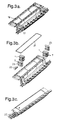
- Figure 3 shows a preferred cable splice closure utilising cable seals according to the invention.
- the closure comprises a casing having a base 17 and a cover 19, and an o-ring seal 21 sealing between the base and the cover.
- the seals 1 are inserted into the ends of the base 17, and the cover 19 is closed on top of them.
- the seals 1 shown in Figure 3 each have four cable apertures 7. Plugs 23 may be provided to block-off any unused cable apertures. Also shown are fastening devices 25 to fasten the cables 27 to the casing.
Landscapes
- Cable Accessories (AREA)
- Installation Of Indoor Wiring (AREA)
- Insertion, Bundling And Securing Of Wires For Electric Apparatuses (AREA)
- Processing Of Terminals (AREA)
Description
- Figure 1
- shows a seal according to the invention;
- Figure 2
- shows a detail of the seal shown in Figure 1; and
- Figure 3
- shows a cable splice closure including two seals according to the invention
Claims (10)
- A seal (1) for sealing between a cable (27) and a casing (17, 19) enclosing part of the cable (27), comprising:wherein:(A) two substantially parallel wall members (3), each having (a) a plurality of substantially concentric removable portions (5) therein which may be selectively removed to provide a cable aperture (7) of required diameter through each of the wall members (3), and (b) a series of retaining portions (13); and(B) sealing material (9) retained between the two wall members (3);(i) the wall members (3) and sealing material (9) are arranged such that, in use, the wall members (3) can be forced towards each other, thereby applying compression to the sealing material (9) and displacing some of it laterally against a cable (27) extending therethrough to seal therearound;(ii) the retaining portions (13) of the wall members (3) are arranged such that each retaining portion (13) is spaced from the others of its series (at least before the wall members (3) are forced towards each other) such that for each diameter of cable aperture (7) which may be selected, there is at least one retaining portion (13) which, in use, substantially prevents exudation of the sealing material (9) next to the cable (27) through the aperture (7) in the wall member (3); and(iii) when a removable portion (5) of the wall member (3) is removed, in use, a corresponding portion of the sealing material (9) is also removed, thereby providing a cable aperture (7) of the required diameter through the sealing material (9).
- A seal (1) according to claim 1, in which each retaining portion (13) extends, in use, between part of the sealing material (9) and a cable (27) extending through the seal (1).
- A seal (1) according to claim 1 or claim 2, in which each retaining portion (13) is flexible.
- A seal (1) according to claim 3 when dependent on claim 2, in which, in use, the sealing material (9) is compressed, thereby causing the or each retaining portion (13) closest to a cable (27) extending through the seal (1) to be flexed against the cable (27).
- A seal (1) according to any preceding claim, in which each portion of sealing material (9) which is removed, in use, when a removable portion (5) of the or each wall member (3) is removed, is separated from the or each adjacent removable portion of the or each wall member by a gap (15).
- A seal (1) according to claim 5, in which, in use, the sealing material (9) is compressed, thereby forcing some of the sealing material (9) into the or each said gap (15).
- A seal (1) according to any preceding claim, which is split to allow side-entry of a cable (27) into the cable aperture (7).
- A seal (1) according to any preceding claim, in which, at least in use, each wall member (3) and the sealing material (9) each have a plurality of said cable apertures (7) extending therethrough.
- A cable splice closure, comprising a casing to enclose the cable splice, and one or more seals (1) according to any preceding claim, to seal an end of the casing.
- Duct sealing apparatus, comprising a casing for attaching to, and sealing, an end of a duct, and one or more seals (1) according to any preceding claim, to seal between the casing and one or more cables (27) extending through the casing and the duct.
Applications Claiming Priority (3)
| Application Number | Priority Date | Filing Date | Title |
|---|---|---|---|
| GBGB9513364.1A GB9513364D0 (en) | 1995-06-30 | 1995-06-30 | Cable seal |
| GB9513364 | 1995-06-30 | ||
| PCT/GB1996/001448 WO1997002636A1 (en) | 1995-06-30 | 1996-06-18 | Cable seal |
Publications (2)
| Publication Number | Publication Date |
|---|---|
| EP0835546A1 EP0835546A1 (en) | 1998-04-15 |
| EP0835546B1 true EP0835546B1 (en) | 2000-10-25 |
Family
ID=10776932
Family Applications (1)
| Application Number | Title | Priority Date | Filing Date |
|---|---|---|---|
| EP96920941A Expired - Lifetime EP0835546B1 (en) | 1995-06-30 | 1996-06-18 | Cable seal |
Country Status (12)
| Country | Link |
|---|---|
| US (1) | US6107571A (en) |
| EP (1) | EP0835546B1 (en) |
| JP (1) | JPH11508757A (en) |
| AR (1) | AR002610A1 (en) |
| AU (1) | AU6232596A (en) |
| BR (1) | BR9609473A (en) |
| CA (1) | CA2225849A1 (en) |
| DE (1) | DE69610770T2 (en) |
| ES (1) | ES2152028T3 (en) |
| GB (1) | GB9513364D0 (en) |
| MX (1) | MX9800227A (en) |
| WO (1) | WO1997002636A1 (en) |
Cited By (2)
| Publication number | Priority date | Publication date | Assignee | Title |
|---|---|---|---|---|
| WO2017046185A3 (en) * | 2015-09-14 | 2017-04-27 | CommScope Connectivity Belgium BVBA | Re-enterable sealed enclosure |
| US9864157B2 (en) | 2011-02-16 | 2018-01-09 | Commscope Technologies Llc | Fiber optic closure |
Families Citing this family (24)
| Publication number | Priority date | Publication date | Assignee | Title |
|---|---|---|---|---|
| GB9513364D0 (en) * | 1995-06-30 | 1995-09-06 | Raychem Sa Nv | Cable seal |
| GB9623230D0 (en) * | 1996-11-07 | 1997-01-08 | Raychem Sa Nv | Cable splice closure |
| SE511456C2 (en) * | 1997-04-07 | 1999-10-04 | Abb Ab | Enclosure for switchgear when distributing electric power and procedure for such enclosure |
| DE59904680D1 (en) * | 1999-08-13 | 2003-04-24 | Ccs Technology Inc | UNIVERSAL CABLE SET |
| JP2001204114A (en) * | 2000-01-20 | 2001-07-27 | Meishin Denki Kk | Distribution line phase color indicating means |
| US6448497B1 (en) * | 2000-08-21 | 2002-09-10 | Mccracken Ronald G. | Cable tray and walkway system |
| SE520363C2 (en) * | 2001-12-14 | 2003-07-01 | Roxtec Int Ab | Entry device for conducting elongated conduit through an opening in a wall |
| US7282644B1 (en) * | 2006-01-17 | 2007-10-16 | Verizon Services Corp. | Aerial cable splice closure |
| SE534991C2 (en) * | 2010-07-14 | 2012-03-06 | Mora Contract Mfg Ab | Sealing module for sealing around an elongated conduit |
| CA139710S (en) | 2010-09-17 | 2012-05-29 | Roxtec Ab | Module for sealing and grounding |
| PL2492565T3 (en) | 2011-02-22 | 2013-12-31 | Hauff Technik Gmbh & Co Kg | Circuit lead through with a sequence of layers |
| USD715744S1 (en) | 2011-03-11 | 2014-10-21 | Roxtec Ab | Cable and pipe penetration seal |
| EP2521230B1 (en) * | 2011-05-05 | 2014-07-09 | CCS Technology, Inc. | Cable closure |
| USD695694S1 (en) | 2011-09-11 | 2013-12-17 | Roxtec Ab | Cable and pipe penetration seal |
| US20150285408A1 (en) * | 2014-04-07 | 2015-10-08 | Superior Tray Systems Inc. | Cable pass through sealing systems |
| WO2017046064A1 (en) * | 2015-09-14 | 2017-03-23 | CommScope Connectivity Belgium BVBA | Sealing block arrangements for enclosures |
| EP3182542B1 (en) * | 2015-12-18 | 2018-01-31 | Axis AB | Cable transit and method for manufacturing such cable transit |
| SE539578C2 (en) * | 2016-04-05 | 2017-10-17 | Mct Brattberg Ab | Insert half, and insert block comprising two of said insert halves |
| DE102017208477A1 (en) * | 2017-05-19 | 2018-11-22 | Icotek Project Gmbh & Co. Kg | Grommet |
| EP3692097A4 (en) * | 2017-10-02 | 2021-07-07 | Commscope Technologies LLC | REMAINING LOW COMPRESSION THERMOPLASTIC GEL AND CABLE GEL SEALING ARRANGEMENT |
| WO2020061283A1 (en) | 2018-09-21 | 2020-03-26 | Commscope Technologies Llc | Fiber optic cable sealing device |
| US12095244B2 (en) * | 2019-09-24 | 2024-09-17 | Commscope Technologies Llc | Composite cable seal |
| CH717235A2 (en) * | 2020-03-17 | 2021-09-30 | Agro Ag | Cable entry. |
| DE102024119102A1 (en) * | 2024-07-04 | 2026-01-08 | Hager Industrie Ag | Seal and insert with one for sealing penetrations of a house connection box |
Family Cites Families (7)
| Publication number | Priority date | Publication date | Assignee | Title |
|---|---|---|---|---|
| BE885312A (en) * | 1979-11-15 | 1981-01-16 | Morel Atel Electromec | SLEEVE FOR PROTECTING THE SPLICE OF ELECTRICAL OR TELEPHONE CABLE |
| FR2501926A2 (en) * | 1981-03-13 | 1982-09-17 | Morel Atel Electromec | Sleeve for sealing of telephone cable inside conduit - has radial openings into annular grooves for insertion of plastics foam filling |
| US4701574A (en) * | 1985-02-06 | 1987-10-20 | Raychem Corp. | Cable sealing apparatus |
| US4704499A (en) * | 1986-06-18 | 1987-11-03 | American Telephone And Telegraph Company At&T Bell Laboratories | Locking mechanism for aerial cable closure and terminals |
| US4857672A (en) * | 1987-12-11 | 1989-08-15 | Minnesota Mining And Manufacturing Company | Cable closure end cap |
| US4822954A (en) * | 1987-12-11 | 1989-04-18 | Minnesota Mining And Manufacturing Company | Cable closure end cap |
| GB9513364D0 (en) * | 1995-06-30 | 1995-09-06 | Raychem Sa Nv | Cable seal |
-
1995
- 1995-06-30 GB GBGB9513364.1A patent/GB9513364D0/en active Pending
-
1996
- 1996-06-18 JP JP9504899A patent/JPH11508757A/en active Pending
- 1996-06-18 ES ES96920941T patent/ES2152028T3/en not_active Expired - Lifetime
- 1996-06-18 BR BR9609473A patent/BR9609473A/en not_active Application Discontinuation
- 1996-06-18 WO PCT/GB1996/001448 patent/WO1997002636A1/en not_active Ceased
- 1996-06-18 DE DE69610770T patent/DE69610770T2/en not_active Expired - Fee Related
- 1996-06-18 AU AU62325/96A patent/AU6232596A/en not_active Abandoned
- 1996-06-18 CA CA002225849A patent/CA2225849A1/en not_active Abandoned
- 1996-06-18 EP EP96920941A patent/EP0835546B1/en not_active Expired - Lifetime
- 1996-06-18 US US08/981,941 patent/US6107571A/en not_active Expired - Fee Related
- 1996-06-26 AR ARP960103333A patent/AR002610A1/en unknown
-
1998
- 1998-01-07 MX MX9800227A patent/MX9800227A/en not_active IP Right Cessation
Cited By (3)
| Publication number | Priority date | Publication date | Assignee | Title |
|---|---|---|---|---|
| US9864157B2 (en) | 2011-02-16 | 2018-01-09 | Commscope Technologies Llc | Fiber optic closure |
| WO2017046185A3 (en) * | 2015-09-14 | 2017-04-27 | CommScope Connectivity Belgium BVBA | Re-enterable sealed enclosure |
| US10371912B2 (en) | 2015-09-14 | 2019-08-06 | CommScope Connectivity Belgium BVBA | Re-enterable sealed enclosure |
Also Published As
| Publication number | Publication date |
|---|---|
| EP0835546A1 (en) | 1998-04-15 |
| GB9513364D0 (en) | 1995-09-06 |
| CA2225849A1 (en) | 1997-01-23 |
| AU6232596A (en) | 1997-02-05 |
| BR9609473A (en) | 1999-03-02 |
| DE69610770T2 (en) | 2001-05-03 |
| ES2152028T3 (en) | 2001-01-16 |
| MX9800227A (en) | 1998-07-31 |
| AR002610A1 (en) | 1998-03-25 |
| WO1997002636A1 (en) | 1997-01-23 |
| US6107571A (en) | 2000-08-22 |
| JPH11508757A (en) | 1999-07-27 |
| DE69610770D1 (en) | 2000-11-30 |
Similar Documents
| Publication | Publication Date | Title |
|---|---|---|
| EP0835546B1 (en) | Cable seal | |
| US6150608A (en) | Seal for sealing an aperture | |
| US6118076A (en) | Cable seal insert | |
| US5883333A (en) | Cable splice closure | |
| US4859809A (en) | Splice case | |
| US7442884B2 (en) | Sealing member for enclosures | |
| EP1127396B1 (en) | Cable closure | |
| EP3436860B1 (en) | Multi-component seal and enclosure | |
| WO1995024756A1 (en) | Sealing arrangement | |
| CA2002628A1 (en) | Closure assembly | |
| EP0628221B1 (en) | Cable seal | |
| EP0835545A1 (en) | Apparatus for enclosing part of an elongate object | |
| EP0880212A2 (en) | Splice closure | |
| MXPA97003943A (en) | He | |
| MXPA98000226A (en) | Apparatus to lock part of an alarg object | |
| JPH10510137A (en) | sticker | |
| MXPA98009095A (en) | Seal to seal an abert |
Legal Events
| Date | Code | Title | Description |
|---|---|---|---|
| PUAI | Public reference made under article 153(3) epc to a published international application that has entered the european phase |
Free format text: ORIGINAL CODE: 0009012 |
|
| 17P | Request for examination filed |
Effective date: 19971204 |
|
| AK | Designated contracting states |
Kind code of ref document: A1 Designated state(s): DE ES FR GB |
|
| 17Q | First examination report despatched |
Effective date: 19980428 |
|
| GRAG | Despatch of communication of intention to grant |
Free format text: ORIGINAL CODE: EPIDOS AGRA |
|
| GRAG | Despatch of communication of intention to grant |
Free format text: ORIGINAL CODE: EPIDOS AGRA |
|
| GRAH | Despatch of communication of intention to grant a patent |
Free format text: ORIGINAL CODE: EPIDOS IGRA |
|
| GRAH | Despatch of communication of intention to grant a patent |
Free format text: ORIGINAL CODE: EPIDOS IGRA |
|
| GRAA | (expected) grant |
Free format text: ORIGINAL CODE: 0009210 |
|
| AK | Designated contracting states |
Kind code of ref document: B1 Designated state(s): DE ES FR GB |
|
| REF | Corresponds to: |
Ref document number: 69610770 Country of ref document: DE Date of ref document: 20001130 |
|
| ET | Fr: translation filed | ||
| REG | Reference to a national code |
Ref country code: ES Ref legal event code: FG2A Ref document number: 2152028 Country of ref document: ES Kind code of ref document: T3 |
|
| PLBE | No opposition filed within time limit |
Free format text: ORIGINAL CODE: 0009261 |
|
| STAA | Information on the status of an ep patent application or granted ep patent |
Free format text: STATUS: NO OPPOSITION FILED WITHIN TIME LIMIT |
|
| 26N | No opposition filed | ||
| REG | Reference to a national code |
Ref country code: GB Ref legal event code: IF02 |
|
| PGFP | Annual fee paid to national office [announced via postgrant information from national office to epo] |
Ref country code: GB Payment date: 20030501 Year of fee payment: 8 |
|
| PGFP | Annual fee paid to national office [announced via postgrant information from national office to epo] |
Ref country code: FR Payment date: 20030602 Year of fee payment: 8 |
|
| PGFP | Annual fee paid to national office [announced via postgrant information from national office to epo] |
Ref country code: ES Payment date: 20030619 Year of fee payment: 8 |
|
| PGFP | Annual fee paid to national office [announced via postgrant information from national office to epo] |
Ref country code: DE Payment date: 20030630 Year of fee payment: 8 |
|
| PG25 | Lapsed in a contracting state [announced via postgrant information from national office to epo] |
Ref country code: GB Free format text: LAPSE BECAUSE OF NON-PAYMENT OF DUE FEES Effective date: 20040618 |
|
| PG25 | Lapsed in a contracting state [announced via postgrant information from national office to epo] |
Ref country code: ES Free format text: LAPSE BECAUSE OF NON-PAYMENT OF DUE FEES Effective date: 20040619 |
|
| PG25 | Lapsed in a contracting state [announced via postgrant information from national office to epo] |
Ref country code: DE Free format text: LAPSE BECAUSE OF NON-PAYMENT OF DUE FEES Effective date: 20050101 |
|
| GBPC | Gb: european patent ceased through non-payment of renewal fee |
Effective date: 20040618 |
|
| PG25 | Lapsed in a contracting state [announced via postgrant information from national office to epo] |
Ref country code: FR Free format text: LAPSE BECAUSE OF NON-PAYMENT OF DUE FEES Effective date: 20050228 |
|
| REG | Reference to a national code |
Ref country code: FR Ref legal event code: ST |
|
| REG | Reference to a national code |
Ref country code: ES Ref legal event code: FD2A Effective date: 20040619 |