EP0835979B1 - Volet roulant et son cache intérieure - Google Patents
Volet roulant et son cache intérieure Download PDFInfo
- Publication number
- EP0835979B1 EP0835979B1 EP97117512A EP97117512A EP0835979B1 EP 0835979 B1 EP0835979 B1 EP 0835979B1 EP 97117512 A EP97117512 A EP 97117512A EP 97117512 A EP97117512 A EP 97117512A EP 0835979 B1 EP0835979 B1 EP 0835979B1
- Authority
- EP
- European Patent Office
- Prior art keywords
- housing part
- roller shutter
- shutter apparatus
- section rail
- housing
- Prior art date
- Legal status (The legal status is an assumption and is not a legal conclusion. Google has not performed a legal analysis and makes no representation as to the accuracy of the status listed.)
- Expired - Lifetime
Links
- 239000011810 insulating material Substances 0.000 claims description 17
- 239000000463 material Substances 0.000 claims description 12
- 229910052751 metal Inorganic materials 0.000 claims description 4
- 239000002184 metal Substances 0.000 claims description 4
- 229910052782 aluminium Inorganic materials 0.000 claims description 2
- XAGFODPZIPBFFR-UHFFFAOYSA-N aluminium Chemical compound [Al] XAGFODPZIPBFFR-UHFFFAOYSA-N 0.000 claims description 2
- 238000005096 rolling process Methods 0.000 claims description 2
- 239000004411 aluminium Substances 0.000 claims 1
- 239000011507 gypsum plaster Substances 0.000 claims 1
- 239000003973 paint Substances 0.000 claims 1
- 239000002245 particle Substances 0.000 claims 1
- 230000007246 mechanism Effects 0.000 description 11
- 239000011505 plaster Substances 0.000 description 9
- 238000009413 insulation Methods 0.000 description 5
- 238000009434 installation Methods 0.000 description 4
- 239000011093 chipboard Substances 0.000 description 2
- 238000010276 construction Methods 0.000 description 2
- 230000002349 favourable effect Effects 0.000 description 2
- 238000012805 post-processing Methods 0.000 description 2
- 238000004804 winding Methods 0.000 description 2
- 230000001133 acceleration Effects 0.000 description 1
- 230000015572 biosynthetic process Effects 0.000 description 1
- 229920002678 cellulose Polymers 0.000 description 1
- 239000001913 cellulose Substances 0.000 description 1
- 238000005253 cladding Methods 0.000 description 1
- 238000004140 cleaning Methods 0.000 description 1
- 238000001125 extrusion Methods 0.000 description 1
- 239000003292 glue Substances 0.000 description 1
- 239000012774 insulation material Substances 0.000 description 1
- 238000012423 maintenance Methods 0.000 description 1
- 239000007769 metal material Substances 0.000 description 1
- 238000003801 milling Methods 0.000 description 1
- 230000002093 peripheral effect Effects 0.000 description 1
- 230000002787 reinforcement Effects 0.000 description 1
- 238000000926 separation method Methods 0.000 description 1
- 230000000007 visual effect Effects 0.000 description 1
- 239000002023 wood Substances 0.000 description 1
Images

Classifications
-
- E—FIXED CONSTRUCTIONS
- E06—DOORS, WINDOWS, SHUTTERS, OR ROLLER BLINDS IN GENERAL; LADDERS
- E06B—FIXED OR MOVABLE CLOSURES FOR OPENINGS IN BUILDINGS, VEHICLES, FENCES OR LIKE ENCLOSURES IN GENERAL, e.g. DOORS, WINDOWS, BLINDS, GATES
- E06B9/00—Screening or protective devices for wall or similar openings, with or without operating or securing mechanisms; Closures of similar construction
- E06B9/02—Shutters, movable grilles, or other safety closing devices, e.g. against burglary
- E06B9/08—Roll-type closures
- E06B9/11—Roller shutters
- E06B9/17—Parts or details of roller shutters, e.g. suspension devices, shutter boxes, wicket doors, ventilation openings
Definitions
- the invention relates to a roller shutter device with a roller shutter shaft for rolling up and down a roller shutter, a first housing part to form a in the installed position in essential vertical inner wall and a second housing part to form a in the installation position essentially horizontal soffit wall, which is in a Intermediate area between a roller shutter level and the inner, first housing part extends, with an at least partially formed by a one-piece h-profile rail Joining point in a between the first housing part and the second housing part defined corner area is formed.
- a roller shutter device is known from German utility model G 93 08 258.4, as it is preferably used in prefabricated wall elements.
- To the Removing the first housing part becomes one in the lower area of the roller shutter box provided fastening screw loosened and then the first housing part pivoted backwards in its lower edge area and subsequently to subtracted below.
- the first housing part arise in the peripheral edge area Parting lines. The assembly and disassembly are also not in the way you want.
- a roller shutter box known, which has a U-shaped housing in cross section, through an upper Plate and two plaster base plates is formed, which is rigidly connected to the upper plate are.
- a cover provided, which is formed by a retaining bar with one in the window frame Engaging groove is engaged.
- a U-shaped bar In a lower side edge area facing the lid the plaster base plate is provided a U-shaped bar, which is both the plaster base plate as well as an insulating layer formed on this and a finished plaster base layer spreads.
- a cleaning strip is loosely inserted into this profile strip, through which the total thickness of one finally to be applied to the plaster base plate Plaster layer is fixed.
- This conventional roller shutter construction There is a risk that if the lower cover is removed later, as may be the case. as part of maintenance work may be required on the plaster base Plaster layer is damaged.
- roller shutter devices are in German Offenlegungsschrift 23 48 730 A1 and German utility model 92 07 463 4, which has a similar configuration of the inner edge area.
- DE-OS 2 752 923 shows a roller shutter box with a profile rail at the bottom End of the inner panel to create a connection between the bottom wall and the back To produce the inner wall of the roller shutter box.
- the profile rail protrudes the rear surface of the vertical inner wall emerges, so that for the viewer no visually appealing sight results.
- the invention is therefore based on the object of a roller shutter device at the outset to improve the type mentioned so that with simple assembly and high structural Skill improves the visual appearance and the post-processing effort is reduced.
- the opposite Leg of the h-profile rail a lower edge of the first, which forms the inner wall Surround part of the housing, while a free leg of the h-profile rail an end face of the second housing part, the second housing part through the h-profile rail is screwed through to the first housing part, and that the first housing part and the one-piece profile rail can be painted over without further treatment or form overtapeable inner surface by the first housing part at least in its Outside area is provided with a milling in which the outer of the opposite Leg of the one-piece h-profile rail is recessed.
- the invention enables a relatively thin one Horizontal plate that covers the roller shutter mechanism on the underside (second housing part) directly with the roller shutter mechanism only covering the inside (wall side) To connect vertical plate, in particular to screw, without taking up space Internal fittings such as strips are provided as connecting elements between the two panels should be. This also makes the interior accessible Improved shutters downwards and enlarged the access opening.
- a Parting line runs directly along a through a front surface of the vertical plate defined vertical plane.
- the roller shutter interior delimited by the first housing part and the second housing part is advantageously with a heat and / or sound insulation device Mistake.
- Such an insulation device advantageously includes a Insulating material arrangement with at least one insulating material body. Preferably there are several Insulating body provided, at least one of the insulating body after can be removed below through the bottom opening exposed by the second housing part is. This makes it possible in an advantageous manner even a relatively thick-walled insulation can be removed in a simple manner from the interior of the roller shutter, so that this may not hinder any further work required. In advantageous In this way, the second housing part can be removed independently of the insulating material body become.
- the first housing part and the second housing part can have essentially the same wall thickness, but they can also differ significantly from each other.
- both housing parts are made of same material, in particular made of a chipboard material.
- the first housing part can also be made with a plasterboard or a cellulose board be provided.
- the outer wall of the first advantageously runs Housing part in the wall plane of the receiving the shutter device Wall element.
- a particularly advantageous embodiment of the invention is given in that the profile strip covers an end face of the first housing part and that second housing part on a front inner surface section of the profile strip that covers the front end of the first housing part, sits.
- An inner panel of the type according to the invention is particularly suitable for cladding of roller shutter mechanisms in rooms with suspended inner ceilings or at Rooms with internal ceilings that are almost at the level of the upper window reveal run.
- This inner panel advantageously comprises a profile strip, which extends along the corner area, the joint between the Profile bar and the second housing part is formed. It is also possible to use the profile bar to attach to the second housing part, so that the joint between the Profile strip and the first housing part runs.
- a particularly advantageous embodiment is given in that the joint between a vertical end face of the second housing part and one of the Roller shutter shaft facing inner surface of the first housing part is formed.
- the first housing part and the second housing part advantageously form a First-time installation of the pre-assembled unit.
- the preferred embodiment of a roller shutter device shown in FIG the invention comprises a first housing part 1 and a substantially rectangular arranged second housing part 2.
- the first housing part 1 and the second housing part 2 form an inner panel for covering a roller shutter mechanism.
- the first housing part 1 and the second housing part 2 are in a lower edge region releasably connected to one another in such a way that the second housing part 2 if necessary is removable to form a floor opening.
- the first housing part 1 it is also possible to also the first housing part 1 if necessary, so that a spread over the entire width and Height of the shutter mechanism extending opening is formed.
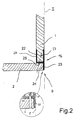
- the profile strip 16 has an H-shaped cross section and with its two mutually parallel holding or fastening legs 27 and 28, as can clearly be seen in FIG. 2, placed on the first housing part 1.
- the profile strip which is h-shaped in cross section, has a free leg 23, which is in one piece formed with the first holding leg 27 and a support section 25 is.
- the free leg 23 is on the support section 25 with the second, to the first holding leg 27 connected spaced holding leg 28 connected. This advantageously ensures that any, in the free leg 23rd horizontal forces introduced are absorbed directly by the first housing part 1 become.
- the second housing part 2 with the first housing part 1 connecting connecting means ensures that the free leg 23 remains rigidly connected to the first housing part 1.
- the profile bar 16 also reinforces the first housing part 1, so that it is comparatively thin can be trained.
- the free leg 23 is formed and extends by a flat strip section only in the plane identified by the letter I in FIG.
- the completely flat, free leg 23 sits directly on a front Front edge of the second housing part and forms with a lower front Corner edge an effectively reinforced corner edge of the roller shutter device or Inner panel.
- One in the area of the joint 9 between the second housing part 2 and the free leg 23 formed gap thus runs directly along one lower inner edge of the free leg 23.
- the distance of the gap to the through the first housing part defined inner plane I corresponds to the wall thickness of the free leg 23. Since the free leg 23 is integral with the second, i.e. inner Holding leg 28 over the support section 25 forming a connecting bridge is connected, a rigid attachment of the free leg 23 is also guaranteed if the second housing part 2 has only a few, comparatively weak Fastening screws are screwed to the first housing part 1.
- an insulating material arrangement which consists of a number of separate Isolierstoff-bodies 3,4,14 is composed. However, these can also be formed in one piece.
- This arrangement of insulating material fills almost the whole Space between the shutter mechanism and the two housing parts 1 and 2 off.
- the insulating material arrangement is essentially semi-cylindrical Provide groove, the fillet surface of which faces the roller shutter shaft 17 and close to the roller shutter when it is fully wound on the roller shutter shaft Roller shutter winding extends.
- the part of the insulating material body that is adjacent to this roller shutter winding can, as shown in this embodiment, formed in two parts be so that an upper insulating body 3 and a lower insulating body 4th is formed, the lower insulating body 4 having a width which is less as a corresponding width of the bottom opening exposed by the second housing part 2.
- the insulating material bodies 3, 4 could also be formed in one piece.
- the lower insulating body 4 is in the shown here Embodiment both with the first housing part 1 and with the second housing part 2 in flat contact and thereby forms a stiffening element, that additionally the corner area formed by the two housing parts 1, 2 stiffened.
- a lower insulating strip 14 which is located on a a frame body 13 facing away from the inner region of the second housing part 2 extends.
- This lower insulating strip has in the embodiment shown here a rectangular cross section. However, it is also possible to change the cross-sectional area this insulating strip, insofar as the shutter mechanism allows it, to enlarge, and in particular to determine the cross section such that the insulating strip 14 continuously merges into the lower insulating part 4.
- the aforementioned Insulation strip 14 is preferably positioned by a small stop bar 18.
- the lower insulating body 4 and the lower insulating strip 14 are in the area of a Actuating belt 19, which is shown here in simplified dashed lines, with corresponding through openings through which the actuating belt 19 is passed.
- the lower insulating body 4 is also included provided recesses provided by pulleys. These are recesses formed such that the lower insulating body 4 is at least pulled down can be.
- the guide rollers 20,21 in the side area arranged of the roller shutter box and in a separately formed from an insulating material Embedded fitting, which during the removal of the lower insulating body 4th at least initially remains in the roller shutter device.
- the second housing part 2 is advantageously provided with through openings, through which the actuating belt 19 is passed.
- a guide part 22 provided, which is connected to the second housing part 2, in particular is screwed.
- a profile rail is on a lower edge of the first housing part 1 16 made of metal or plastic, through which the second housing 2 screwed to the first housing part 1 in spite of the small material cross sections is, since the metal mounting rail 16 practically reinforces the underside of the first housing part 1 (vertical plate).
- a downward free one Leg 23 of the metal mounting rail 16 also covers the end face of the second Housing part 2 from, so that a durable as well as easy assembly arrangement is formed, which at the same time maximum accessibility of an interior of the roller shutter device guaranteed.
- the corner area between the first housing part 1 and the second housing part 2 provided profile rail 16, which can also consist of plastic material, a particularly clean one Separate these two housing parts.
- profile rail 16 can also consist of plastic material, a particularly clean one Separate these two housing parts.
- the first housing part 1 and the profile strip 16 one that can be painted over or taped over without further post-processing
- the first housing part is at least in its outer region provided with a cutout 22 in which a corresponding material strip section the profile bar 16 is received sunk.
- the profile strip 16 further comprises a support section 25 which has a lower end face of the first housing part 1 covers. Sits on this support section 25 corresponding inner wall section of the second housing part 2.
- the arrangement of the profile strip 16 made here proves to be particularly good favorable disassembly of the second housing part 2 in particular in connection with an inside seal on the second housing part 2 Particularly advantageous in terms of improved moisture resistance.
- the profile strip used here can for example be made of a plastic or a Be made of metal material.
- the profile strip 16 advantageously consists of a aluminum profile made by extrusion.
- the first housing part 1 and the second housing part 2 are advantageously made of a wood material, in particular a chipboard.
- the joint 9 is advantageously between the front end face 24 of the second housing part 2 and the inner surface of the first housing part 1 is formed.
- the connecting screw is loosened and the housing part 2 pivoted slightly so far down that an inner surface of the second housing part 2 below a lower edge of the profile strip comes to rest. Then the second housing part 2 is inclined downwards from the The shutter device is removed. Then the lower insulating material part 4 can that is now formed between the frame body 13 and the first housing part 1 Bottom opening can be removed downwards. After removing the lower part of the insulating material 4 can if necessary also the lower insulating strip 14 from the Roller shutter device can be removed.
- the first housing part 1 can also be from the roller shutter device be removed. For this purpose, the lower end of the first housing part 1 seized and slightly pivoted forward. Then the first housing part 1 be pulled down. Here comes one in the upper edge area of the first housing part 1 provided holding clip 11 out of engagement with a for example attached to a crossbar of a wall element retaining strip 12. In the area of one formed by the holding clip 11 and the holding strip 12 Upper holding device 10 is formed an attachment 8, which is the formation of a allows relatively clean parting line. For this purpose, in the area of the attachment point 8 Plastic strip element is provided, which forms a flat interface.
- the aforementioned upper holding device 10 and the first housing part 1 are preferred assembled into a pre-assembled unit so that when you first Attaching the first housing part to a corresponding wall element, only the retaining bar is preferably attached via screws. Only afterwards Removing the first housing part 1, the first housing part 1 of the Holding bar 10 separated for the first time.
- the first housing part 1 and the second housing part 2 are preferably also assembled in the factory to a pre-assembled panel element and can as a preassembled assembly in this way on an assembly which is already in a wall element Roller shutter mechanism can be placed, or also in the factory, with the Roller shutter mechanism, especially for a completely pre-assembled roller shutter box be put together.
- the invention is not restricted to the exemplary embodiments described above.
Landscapes
- Engineering & Computer Science (AREA)
- Structural Engineering (AREA)
- Architecture (AREA)
- Civil Engineering (AREA)
- Operating, Guiding And Securing Of Roll- Type Closing Members (AREA)
- Casings For Electric Apparatus (AREA)
Claims (19)
- Volet roulant avec un arbre de volet roulant (17), pour enrouler et dérouler un volet roulant, une première partie de boítier (1) pour former une paroi intérieure sensiblement verticale lorsqu'elle est en position montée, et une deuxième partie de boítier (2) pour former une paroi de surface intérieure, sensiblement horizontale lorsqu'elle est en position montée, qui s'étend dans une zone intermédiaire, entre un plan de volet roulant (E) et la première partie de boítier (1) intérieure, avec un point de jointoiement (9), formé au moins partiellement par un rail à profil en h (16), réalisé d'une seule pièce, point de jointoiement réalisé dans une zone d'angle définie entre la première partie de boítier (1) et la deuxième partie de boítier (2), caractérisé en ce queles ailes (27, 28), en regard l'une de l'autre, du rail à profil en h (16) entourent un bord inférieur de la première partie de boítier (1) constituant la paroi intérieure, tandis qu'une aile libre (23) du rail à profil en h couvre une face frontale de la deuxième partie de boítier (2),la deuxième partie de boítier (2) est vissée à la première partie de boítier (1) par un vissage traversant le rail à profil en h (16), et en ce que la première partie de boítier (1) et le rail profilé (16) d'une seule pièce forment une surface intérieure (I), susceptible d'être enduite ou tapissée, sans autre traitement postérieur, en ce que la première partie de boítier (1) est munie, au moins dans sa zone extérieure, d'une fraisure (22) dans laquelle est logé, de façon noyée, celle, située à l'extérieur, des ailes (27), placées en regard, du rail à profil en h (16) réalisé d'une seule pièce.
- Volet roulant selon la revendication 1, caractérisé en ce que, dans la zone de bord de la première partie de boítier (1), la face d'assise, constituée par une fraisure (22), d'une aile de maintien (27) se raccorde de façon affleurée à la face frontale avant de la deuxième partie de boítier (2).
- Volet roulant selon la revendication 1 ou 2, caractérisé en ce que l'aile libre (23), en position montée, ressort en direction verticale vers le bas sur une face frontale de la première partie de boítier (1), et s'étend à plat dans la face intérieure (I) définie par le premier boítier (1).
- Volet roulant selon au moins l'une des revendications 1 à 3 précédentes, caractérisé en ce qu'un interstice, défini par le point de jointoiement (9), s'étend dans un bord d'angle, entre la deuxième partie de boítier (2) et une face intérieure, tournée vers la face frontale de la deuxième partie de boítier (2), de l'aile libre (23).
- Volet roulant selon au moins l'une des revendications 1 à 4 précédentes, caractérisé en ce que l'aile libre (23) et la première aile (27) limitrophe sont disposées dans un plan commun, et en ce que le bord d'angle est constitué par l'extrémité libre de l'aile libre (23), dans le plan commun, l'interstice s'étendant, le long du bord d'angle, à une distance qui correspond à l'épaisseur de paroi de l'aile libre (23).
- Volet roulant selon au moins l'une des revendications 1 à 5 précédentes, caractérisé en ce que le bord avant de la deuxième partie de boítier (2) s'étend exactement le long de l'extrémité inférieure de l'aile libre (23) du rail à profil en h (16) et est légèrement chanfreiné.
- Volet roulant selon au moins l'une des revendications 1 à 6 précédentes, caractérisé en ce que le rail à profil en h (16) est susceptible d'être enfiché sur un bord inférieur de la première partie de boítier.
- Volet roulant selon au moins l'une des revendications 1 à 7, caractérisé en ce que le rail à profil en h (16) est une bande profilée métallique, en particulier une bande profilée en aluminium.
- Volet roulant selon au moins l'une des revendications 1 à 7 précédentes, caractérisé en ce que le rail à profil en h (16) est une bande profilée en matière synthétique.
- Volet roulant selon au moins l'une des revendications 1 à 9 précédentes, caractérisé en ce que la première partie de boítier (1) est un corps en forme de plaque, s'étendant entre un point de placement supérieur (8) et le point de jointoiement (9).
- Volet roulant selon au moins l'une des revendications 1 à 10 précédentes, caractérisé en ce que, dans la zone de bord supérieur de la première partie de boítier (1), est prévue, faisant partie d'un dispositif de maintien supérieur (10), une pince de maintien (11) et, dans la zone du point d'application (8), est prévu un élément en bande en matière synthétique, qui constitue une surface de séparation plane.
- Volet roulant selon au moins l'une des revendications 1 à 11 précédentes, caractérisé en ce que la deuxième partie de boítier (2) est un corps en forme de plaque, susceptible d'être démonté vers le bas, pour libérer une ouverture de fond et/ou en ce que la première partie de boítier (1) est susceptible d'être enlevée latéralement pour libérer une ouverture latérale.
- Volet roulant selon au moins l'une des revendications 1 à 12 précédentes, caractérisé en ce que la première partie de boítier (1) et la deuxième partie de boítier (2) présentent sensiblement la même épaisseur de paroi.
- Volet roulant selon au moins l'une des revendications 1 à 13 précédentes, caractérisé en ce qu'au moins l'une des parties de boítier (1, 2) est constituée d'un matériau ligneux, en particulier d'un matériau en panneau de particules.
- Volet roulant selon au moins l'une des revendications 1 à 14 précédentes, caractérisé en ce que la première partie de boítier (1) est constituée en un matériau d'isolation, ou bien munie d'une plaque en carton-plâtre ou d'une plaque en matériau alvéolaire.
- Volet roulant selon au . moins l'une des revendications 1 à 15 précédentes, caractérisé en ce que la première partie de boítier (1) et la deuxième partie de boítier (2) constituent un ensemble de construction prémonté à l'occasion du premier montage.
- Volet roulant selon au moins l'une des revendications 1 à 16 précédentes, caractérisé en ce qu'un agencement en substance isolante, muni d'au moins un corps en substance isolante (3, 4, 14), est prévu dans un espace intérieur délimité par les parties de boítier (1, 2).
- Volet roulant selon au moins l'une des revendications 1 à 17 précédentes, caractérisé en ce qu'au moins un corps en matériau isolant (4, 14) est susceptible d'être enlevé vers le bas, par une ouverture de fond pouvant être libérée par la deuxième partie de boítier (2), et en ce que la deuxième partie de boítier (2) est susceptible d'être enlevée indépendamment du corps en matériau isolant (3, 4, 14).
- Volet roulant selon au moins l'une des revendications 1 à 18 précédentes, caractérisé en ce qu'au moins un corps en matériau isolant (4) est en contact de surface, tant avec la première partie de boítier (1), qu'également avec la deuxième partie de boítier (2), et sert alors d'élément de rigidification, conférant une rigidité supplémentaire à la zone d'angle constituée par les deux parties de boítier (1, 2).
Applications Claiming Priority (2)
| Application Number | Priority Date | Filing Date | Title |
|---|---|---|---|
| DE29617594U | 1996-10-09 | ||
| DE29617594U DE29617594U1 (de) | 1996-10-09 | 1996-10-09 | Rolladenvorrichtung und Innenblende hierfür |
Publications (2)
| Publication Number | Publication Date |
|---|---|
| EP0835979A1 EP0835979A1 (fr) | 1998-04-15 |
| EP0835979B1 true EP0835979B1 (fr) | 2001-06-20 |
Family
ID=8030379
Family Applications (1)
| Application Number | Title | Priority Date | Filing Date |
|---|---|---|---|
| EP97117512A Expired - Lifetime EP0835979B1 (fr) | 1996-10-09 | 1997-10-09 | Volet roulant et son cache intérieure |
Country Status (4)
| Country | Link |
|---|---|
| EP (1) | EP0835979B1 (fr) |
| AT (1) | ATE202403T1 (fr) |
| CZ (1) | CZ7335U1 (fr) |
| DE (2) | DE29617594U1 (fr) |
Families Citing this family (1)
| Publication number | Priority date | Publication date | Assignee | Title |
|---|---|---|---|---|
| DE29806310U1 (de) | 1998-04-07 | 1998-07-30 | Home-Fertigelemente GmbH, 59872 Meschede | Rolladenkasten mit Wärmedämmkörper |
Family Cites Families (8)
| Publication number | Priority date | Publication date | Assignee | Title |
|---|---|---|---|---|
| DE2348730A1 (de) * | 1973-09-28 | 1975-04-10 | Werner Dubiel | Rolladenkasten mit vertikalem deckel |
| DE2752923C2 (de) * | 1977-11-26 | 1985-04-11 | Hubert 4250 Bottrop Langen | Rolladenkasten |
| DE8105110U1 (de) * | 1981-02-24 | 1981-08-13 | Langer, Franz, 6400 Fulda | Rolladenkasten |
| DE3419206C2 (de) * | 1984-05-23 | 1993-10-21 | Joma Daemmstoffwerk Josef Mang | Rolladenkasten |
| ATE95882T1 (de) * | 1986-03-22 | 1993-10-15 | Augsburger Ver Ziegelwerke | Vorgefertigter rolladenkasten aus aneinanderstossenden ziegelformsteinen, sowie verfahren zur herstellung desselben. |
| DE8802974U1 (de) * | 1988-03-05 | 1988-04-21 | Kiesl, Georg, 8474 Oberviechtach | Zusatzdeckel für Rolladenkasten mit innenliegender Montageöffnung |
| DE9207463U1 (de) * | 1992-06-03 | 1992-08-13 | Wiehofsky, Fritz, 8913 Schondorf | Rolladenkasten mit Isolierkörper |
| DE9308258U1 (de) * | 1993-06-02 | 1993-10-21 | D & M Rolladentechnik GmbH, 56204 Hillscheid | Rolladenkasten |
-
1996
- 1996-10-09 DE DE29617594U patent/DE29617594U1/de not_active Expired - Lifetime
-
1997
- 1997-10-06 CZ CZ19977243U patent/CZ7335U1/cs active Protection Beyond IP Right Term
- 1997-10-09 AT AT97117512T patent/ATE202403T1/de active
- 1997-10-09 DE DE59703854T patent/DE59703854D1/de not_active Expired - Lifetime
- 1997-10-09 EP EP97117512A patent/EP0835979B1/fr not_active Expired - Lifetime
Also Published As
| Publication number | Publication date |
|---|---|
| DE29617594U1 (de) | 1996-11-21 |
| ATE202403T1 (de) | 2001-07-15 |
| EP0835979A1 (fr) | 1998-04-15 |
| CZ7335U1 (cs) | 1998-05-05 |
| DE59703854D1 (de) | 2001-07-26 |
Similar Documents
| Publication | Publication Date | Title |
|---|---|---|
| DE69001096T2 (de) | Abgedichteter schaltschrank. | |
| CH653873A5 (de) | Duschtrennwand. | |
| DE69903367T2 (de) | Rolladenkasten | |
| EP0918127B1 (fr) | Châssis de porte et dispositif de montage | |
| EP0835979B1 (fr) | Volet roulant et son cache intérieure | |
| EP0812045B1 (fr) | Conduit pour câbles pour des pièces à l'intérieur d'immeubles | |
| EP2687666B1 (fr) | Module pour la réception d'une porte coulissante et procédé de montage d'un module pour une porte coulissante | |
| EP0940518A1 (fr) | Elément de revêtment pou murs de batiments | |
| DE3426653A1 (de) | Dachgaube | |
| EP0230998A2 (fr) | Vantail de porte à ouvertures pour la ventilation | |
| AT525231B1 (de) | Raffstorekasten und Verbindungsbeschlag zur Befestigung des Raffstores | |
| DE10145052B4 (de) | Satz von Innenfutterprofilleisten | |
| EP0736436B1 (fr) | Véhicule ferroviaire | |
| EP1990477B1 (fr) | Panneau de construction léger doté d'une baguette de profilé | |
| DE602006000676T2 (de) | Vorrichtung zur Verwirklichung oder Erneuerung von Innentüren | |
| DE9400053U1 (de) | Abschlußprofil, insbesondere Türschwellenprofil | |
| EP0409029A1 (fr) | Profilé pour le support de panneaux de plafond | |
| EP0987396A2 (fr) | Habillage pour fenêtres ou portes | |
| EP0456004B1 (fr) | Elément latéral d'un revêtement intérieur pour une fenêtre lucarne et kit de montage pour la fabrication d'un tel revêtement | |
| DE8431499U1 (de) | Renovierungs-tuerfutter | |
| DE19925111C1 (de) | Dachgaube | |
| EP1211378A1 (fr) | Caisson de volet roulant avec une trappe de visite | |
| DE202012002712U1 (de) | Pfostenverbinder | |
| DE29616491U1 (de) | Anschlußprofil zum Anschließen plattenförmiger Bauelemente insbesondere an in Öffnungen von Baukörpern eingesetzten Fenster- oder Türrahmen | |
| DE29923088U1 (de) | In eine Öffnung in einer Gebäudewand einsetzbarer Erker |
Legal Events
| Date | Code | Title | Description |
|---|---|---|---|
| PUAI | Public reference made under article 153(3) epc to a published international application that has entered the european phase |
Free format text: ORIGINAL CODE: 0009012 |
|
| AK | Designated contracting states |
Kind code of ref document: A1 Designated state(s): AT DE FR IT |
|
| AX | Request for extension of the european patent |
Free format text: AL;LT;LV;RO;SI |
|
| 17P | Request for examination filed |
Effective date: 19980930 |
|
| AKX | Designation fees paid |
Free format text: AT DE FR IT |
|
| RBV | Designated contracting states (corrected) |
Designated state(s): AT DE FR IT |
|
| 17Q | First examination report despatched |
Effective date: 19981217 |
|
| GRAG | Despatch of communication of intention to grant |
Free format text: ORIGINAL CODE: EPIDOS AGRA |
|
| GRAG | Despatch of communication of intention to grant |
Free format text: ORIGINAL CODE: EPIDOS AGRA |
|
| GRAH | Despatch of communication of intention to grant a patent |
Free format text: ORIGINAL CODE: EPIDOS IGRA |
|
| GRAH | Despatch of communication of intention to grant a patent |
Free format text: ORIGINAL CODE: EPIDOS IGRA |
|
| GRAA | (expected) grant |
Free format text: ORIGINAL CODE: 0009210 |
|
| AK | Designated contracting states |
Kind code of ref document: B1 Designated state(s): AT DE FR IT |
|
| PG25 | Lapsed in a contracting state [announced via postgrant information from national office to epo] |
Ref country code: IT Free format text: LAPSE BECAUSE OF FAILURE TO SUBMIT A TRANSLATION OF THE DESCRIPTION OR TO PAY THE FEE WITHIN THE PRESCRIBED TIME-LIMIT;WARNING: LAPSES OF ITALIAN PATENTS WITH EFFECTIVE DATE BEFORE 2007 MAY HAVE OCCURRED AT ANY TIME BEFORE 2007. THE CORRECT EFFECTIVE DATE MAY BE DIFFERENT FROM THE ONE RECORDED. Effective date: 20010620 Ref country code: FR Free format text: LAPSE BECAUSE OF FAILURE TO SUBMIT A TRANSLATION OF THE DESCRIPTION OR TO PAY THE FEE WITHIN THE PRESCRIBED TIME-LIMIT Effective date: 20010620 |
|
| REF | Corresponds to: |
Ref document number: 202403 Country of ref document: AT Date of ref document: 20010715 Kind code of ref document: T |
|
| REF | Corresponds to: |
Ref document number: 59703854 Country of ref document: DE Date of ref document: 20010726 |
|
| EN | Fr: translation not filed | ||
| PLBE | No opposition filed within time limit |
Free format text: ORIGINAL CODE: 0009261 |
|
| STAA | Information on the status of an ep patent application or granted ep patent |
Free format text: STATUS: NO OPPOSITION FILED WITHIN TIME LIMIT |
|
| 26N | No opposition filed | ||
| PGFP | Annual fee paid to national office [announced via postgrant information from national office to epo] |
Ref country code: DE Payment date: 20161027 Year of fee payment: 20 |
|
| PGFP | Annual fee paid to national office [announced via postgrant information from national office to epo] |
Ref country code: AT Payment date: 20161026 Year of fee payment: 20 |
|
| REG | Reference to a national code |
Ref country code: DE Ref legal event code: R071 Ref document number: 59703854 Country of ref document: DE |
|
| REG | Reference to a national code |
Ref country code: AT Ref legal event code: MK07 Ref document number: 202403 Country of ref document: AT Kind code of ref document: T Effective date: 20171009 |