EP0836009B1 - Vacuum pump in combination with an electronic control unit - Google Patents
Vacuum pump in combination with an electronic control unit Download PDFInfo
- Publication number
- EP0836009B1 EP0836009B1 EP97109536A EP97109536A EP0836009B1 EP 0836009 B1 EP0836009 B1 EP 0836009B1 EP 97109536 A EP97109536 A EP 97109536A EP 97109536 A EP97109536 A EP 97109536A EP 0836009 B1 EP0836009 B1 EP 0836009B1
- Authority
- EP
- European Patent Office
- Prior art keywords
- combination
- casing
- vacuum pump
- motor
- pwm
- Prior art date
- Legal status (The legal status is an assumption and is not a legal conclusion. Google has not performed a legal analysis and makes no representation as to the accuracy of the status listed.)
- Revoked
Links
- 238000005086 pumping Methods 0.000 claims description 16
- 238000001816 cooling Methods 0.000 claims description 14
- 239000002184 metal Substances 0.000 claims description 5
- 230000005284 excitation Effects 0.000 claims description 4
- 239000007789 gas Substances 0.000 description 8
- 230000033228 biological regulation Effects 0.000 description 3
- 230000000694 effects Effects 0.000 description 3
- 238000004804 winding Methods 0.000 description 3
- 238000010276 construction Methods 0.000 description 2
- 230000001276 controlling effect Effects 0.000 description 2
- 238000010586 diagram Methods 0.000 description 2
- 238000001914 filtration Methods 0.000 description 2
- 238000004891 communication Methods 0.000 description 1
- 230000006835 compression Effects 0.000 description 1
- 238000007906 compression Methods 0.000 description 1
- 239000004020 conductor Substances 0.000 description 1
- 230000001419 dependent effect Effects 0.000 description 1
- 230000020169 heat generation Effects 0.000 description 1
- 239000000314 lubricant Substances 0.000 description 1
- 230000003287 optical effect Effects 0.000 description 1
- 230000001105 regulatory effect Effects 0.000 description 1
- 239000011347 resin Substances 0.000 description 1
- 229920005989 resin Polymers 0.000 description 1
- 230000000284 resting effect Effects 0.000 description 1
- 238000007789 sealing Methods 0.000 description 1
Images


Classifications
-
- F—MECHANICAL ENGINEERING; LIGHTING; HEATING; WEAPONS; BLASTING
- F04—POSITIVE - DISPLACEMENT MACHINES FOR LIQUIDS; PUMPS FOR LIQUIDS OR ELASTIC FLUIDS
- F04D—NON-POSITIVE-DISPLACEMENT PUMPS
- F04D27/00—Control, e.g. regulation, of pumps, pumping installations or pumping systems specially adapted for elastic fluids
-
- F—MECHANICAL ENGINEERING; LIGHTING; HEATING; WEAPONS; BLASTING
- F04—POSITIVE - DISPLACEMENT MACHINES FOR LIQUIDS; PUMPS FOR LIQUIDS OR ELASTIC FLUIDS
- F04D—NON-POSITIVE-DISPLACEMENT PUMPS
- F04D19/00—Axial-flow pumps
- F04D19/02—Multi-stage pumps
- F04D19/04—Multi-stage pumps specially adapted to the production of a high vacuum, e.g. molecular pumps
Definitions
- the present invention relates to a control unit or controller for a vacuum pump, particularly for a vacuum pump of the turbomolecular type.
- a turbomolecular vacuum pump comprises a plurality of pumping stages housed within a substantially cylindrical casing and provided with an axial inlet port of the sucked gases located at one end, and with a radial or axial exhaust port of the gases located at the opposed end.
- Said pumping stages generally comprise a rotor disk, secured to the rotatable shaft of the pump, that is driven by an electric motor at a speed usually not lower than 25,000 rpm and in case as high a 100,000 rpm.
- the rotor disk rotates within stator rings fastened to the pump casing and defining the stator of the pumping stage, with a very small gap therebetween.
- a pumping channel of the sucked gases is further defined.
- the pumping channel defined between the rotor and the stator in each pumping stage communicates with the preceding and the subsequent pumping stages through a suction port and an exhaust port, respectively, provided through the stator in correspondence of the pumping channel of the sucked gases.
- a turbomolecular pump of the above type is disclosed for example in EP-A-0 445 855 in the name of the present applicant.
- turbomolecular pump described in EP-A-0 445 855 employes both pumping stages provided with rotors formed as flat disks and pumping stages provided with rotor equipped with blades.
- This combined arrangement of pumping stages allows for a very good performance of the pump for what concerns the compression ratio, while allowing to discharge the gases into the outer environment at atmospheric pressure by means of simple pre-vacuum pumps without lubricant, such as diaphragm pumps.
- a control unit for a vacuum pump equipped with an asynchronous motor is disclosed in DE 41 13 068 which employs a microprocessor for controlling a three phase pulse width modulated waveform generator and a plurality of FET switches.
- the FET switches modulate a direct current originated from a power supplier so as to obtain a three phase voltage system for feeding the asynchronous motor of the pump.
- said known unit Because of the overall size and the cooling requirements mainly caused by the presence of the transformer, said known unit must be mounted separately from the turbomolecular pump and be provided with dedicated cooling devices in addition to those already provided for cooling the pump.
- the feeding voltage level must be changed during the operating cycle on the basis of the residual pressure within the vacuum pump and the operating conditions of the pump motor from the starting condition to the steady state rotating condition.
- control units of the above described type for vacuum pumps capable of supplying the vacuum pump with a plurality of voltages that are selected as a function of the pump current, and therefore as a function of the pressure level inside the pump.
- the voltage applied to the motor of the pump can be adjusted, for example through an SCR or a TRIAC controlled rectifying bridge.
- the voltage level of the mains can be varied, for example, through a transformer having a primary winding divided into a number of sections that are connected to as many switch contacts.
- the object of the present invention is to realize a compact control unit for vacuum pumps, more particularly of the turbomolecular type, capable of varying the feeding voltage level supplied to the pump motor, and capable of accomodating substantially all the voltages commonly available on the public power distribution networks.
- the basic concept exploited by the present invention to regulate the voltage supplied to the motor of a vacuum pump is that of providing means for periodically interrupting the drive signals in the feeding circuit of the vacuum pump motor in such a way as to modify the rms (root mean squared) value of at least one of the e.m.f.s (electromotive forces) forming the e.m.f. or voltage system generated by the control unit and feeding the motor.
- rms value of an voltage is inversely proportional to the duration of the switched-off intervals, such rms value can be modified in a wide range by properly adjusting the duration of the switching intervals.
- the three-phase system of square-wave voltages for feeding the motor of the vacuum pump is generated by the circuit disclosed in details hereinbelow with reference to Figures 1, 2 and 3a to 3g.
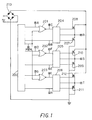
- the circuit illustrated in Figure 1 substantially comprises a microprocessor 200 connected to three AND gates 201, 202, 203, three IC gate drivers 204, 205, 206 each having one input connected to the microprocessor 200 and the other to the output of one of the above AND gates, three pairs of transistors, e.g. of the MOSFET type, indicated by the references from 207 to 212.
- the two MOSFET transistors of each pair are connected in series with each other, with both the two transistor gates and the common junction terminals R, S, T of the series connection connected to as many outputs of the corresponding AND gate.
- For each transistor pair one of the remaining terminals (the source of transistor 208 in Fig. 1) is connected to a D.C. supply voltage while the other (the drain of transistor 207) is grounded.
- the D.C. voltage is obtained through a diode bridge 213 properly connected to the mains.
- the diode bridge 213 Through the diode bridge 213 the alternating current from the mains is rectified and directly applied, i.e. without any intermediate voltage regulator, across the series connection of each pair of the six MOSFET transistors 207 to 212.
- each of the pairs of MOSFET transistors 207 to 212 generates one of the voltages of a three-phase system to feed the three-phase asynchronous motor of the vacuum pump.
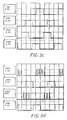
- Figure 2 illustrates the signals A, B, D, E, G, H, generated by microprocessor 200 for driving the MOSFET transistors 207 to 212 through the gate drivers 204, 205 and 206.
- the terminals on which such signals are present are labelled with the same references as the signals.
- Signals B, E and H are shown as negative since they relate to "low" inputs of the gate drivers 204, 205 and 206 for driving those of the MOSFET transistors having a terminal connected to ground.
- the frequency of said signals A, B, D, E, G and H corresponds to the excitation frequency of the asynchronous motor driving the vacuum pump.
- the microprocessor 200 further generates a PWM signal, formed by pulses having a constant frequency and duration capable of being modulated, which signal is applied to the second input of each AND gates 201, 202 and 203 for intermittently enabling (opening and closing) such AND gates.
- FIG. 2 illustrates the widths or durations of said PWM signal when modulated by pulses having widths d, d' or d'', respectively.
- Each of the waveforms C, F and I in Figure 2 show the signals at the outputs of AND gates 201, 202 and 203, respectively, generated by the above intermittent opening and closing of the AND gates by the pulsating PWM, i.e. the ANDings of PWM signal with signals A, D and G, respectively.
- the signals C, F and I are intermittent, i.e. formed by spaced bursts or trains of pulses with the duration of the burst corresponding to the time the signals A, D or G respectively is high, and the spacing to the time for which such signals are low.
- Signals C, F and I are applied to one input of the gate drivers 204, 205 and 206, and generates outputs used for driving those (208, 210, 212) of the MOSFET transistors that are not connected to ground.
- each pair of terminals R-S, S-T and T-R there will be generated the square wave signals C, F and I of Fig. 2, respectively, that are out of phase by 120° from each other and intermittent, i.e. formed by spaced bursts or trains of pulses with the duration of the burst corresponding to the time the signals A, D or G respectively is high, and the spacing to the time for which such signals are low.
- Signals C, F and I are applied to one input of the gate drivers 204, 205 and 206, and generates outputs used for driving those (208, 210, 212) of the MOSFET transistors that are not connected to ground.
- the so generated voltage system is a three-phase system of square wave voltages in which the voltage level is periodically zeroed for an interval the duration of which depends on the PWM signal.
- the rms voltage of said three-phase voltage system will be proportional to the pulse width of the PWM signal generated by the microprocessor 200.
- the frequency of the PWM signal is generally selected in the range between 5 and 20 times the excitation frequency of the asynchronous motor.
- the power dissipated in the MOSFET transistors 207 to 213 mainly depends on the number of their ON/OFF switchings, and since it is sufficient to cut off only one MOSFET transistor in each pair of MOSFET transistors 207 to 213 to block the flow of the feeding current to each of the terminals R, S and T, in order to reduce the heat generation, then the pulsating signal PWM is combined only with the signals driving one transistor of each pair of the MOSFET transistors 207 to 213.
- a voltage duplicating device can be provided in the network feeding line for extending the working range of the electronic control unit from about 90 to 260 V a.c.
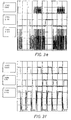
- Figures 3a to 3g show the real waveforms of some of the most significant signals in the circuit of Figure 1 at different rotation speeds of an asynchronous motor driving the vacuum pump.
- Figure 3a relates to a steady state rotation of the vacuum pump motor at 21,000 rpm
- Figure 3b to a steady state rotation at 24,000 rpm
- Figure 3c to a steady state rotation at 62,000 rpm
- Figure 3d to a steady state rotation at 62,000 rpm
- Figure 3e to a steady state rotation at 13,000 rpm
- Figure 3f to a steady state rotation at 60,000 rpm
- Figure 3g to a steady state rotation at 62,000 rpm.
- the above described circuit can be equipped with means that are known to the skilled in the art for other types of motors that drive vacuum pumps, such as for example motors of the "brushless” type (without brushes) or “switched reluctance” (S.R.) motors.
- the frequency of the PWM signal must vary as a function of the rotor position and therefore a return signal has to be provided that contains information relating to the rotor position in the motor.
- This signal is processed by the microprocessor 200 and supplied, for example, to an optical or magnetic position sensor provided in the motor (not shown in the drawings).
- a first alternative embodiment of the control unit of the present invention can generate the voltage system and regulate the feeding voltage by using a small insulating transformer fed by the network voltage that has been rectified and modulated at high frequency, typically 100 kHz, with a mean value equal to zero.
- the voltage across the secondary winding of such small transformer is rectified again, filtered and used to drive transistors that feed the vacuum pump motor.
- the value of the motor drive voltage can be regulated by varying the rms voltage of the high frequency signal feeding the primary winding of the small transformer through the combination of a PWM signal in accordance with the principle described in the preferred embodiment.
- the dimensions of the transformer can be reduced to a minimum since the operating frequency is high.
- the voltage system and the regulation of the feeding voltage are accomplished through an L-C filtering group with a recirculation diode fed by the distribution network voltage that has been rectified and modulated at high frequency with a mean value different from zero.
- the regulation of the drive voltage for the motor is obtained by varying the "duty cycle" of the high frequency voltage applied the L-C filtering group through the combination of a PWM signal in accordance with the principle described in the preferred embodiment.
- the electronic control unit of the present invention is integrated in a turbomolecular pump, indicated as a whole by reference 100.
- the turbomolecular pump 100 comprises a substantially cylindrical casing 101, having a first portion 102 and a second portion 103, coaxial to the former and with a smaller section.
- the first portion 102 houses the gas pumping stages and is provided with an axial suction port 119 at one end and a radial exhaust port 120 at the opposed end, while the second portion 103 houses the motor and the support bearings for the shaft of the turbomolecular pump 100.
- a plurality of annular grooves 104 defining a series of cooling fins or rings 105 is provided on the outer surface of the first larger portion 102 of the casing 101.
- Annular grooves 108, defining a series of cooling rings 109 are also provided on the outer surface of the second smaller portion 103 of the casing 101.
- the turbomolecular pump 100 is further provided with an annular protruding ring or flange 110 with peripherally spaced holes 117 for securing the turbomolecular pump 100 to the vessel or chamber (not shown) in which vacuum is to be created.
- the turbomolecular pump 100 comprises a monolithic rotor 112 in which there are formed rotor disks 113 having flat surfaces and rotor disks 114 equipped with blades.
- Said rotor disks 113 and 114 are radially located inside stator rings 115 and 116, respectively, for forming pumping channels for the gases.
- control unit 1 comprises a housing 2 having a lower resting surface 3, an upper closure surface 4, and side 5 and 6.
- the side 6 comprises a rounded portion 12 and two linear portions 13, substantially parallel to each other.
- the upper closure surface 4 is provided with a circular opening 16 for the passagge of the second portion 103 of the already discussed cylindrical casing 101.
- the second portion 103 is therefore completely housed inside the space provided in the casing 2, while the first portion 102 of said cylindrical casing 101 is outside the casing 2.
- a removable cap 10 for accessing to a device safety fuse (not shown), a sealing ring 11 for the passage of the supply cable 50 comprising a plurality of leads to the electronic control unit 1, and connectors 51, 52 and 53 for the communication and the control of unit 1 by means of an external unit (not shown), if required.
- the electronic control unit 1 further comprises leads 60 (Fig. 7) for feeding the three-phase asynchronous motor of the vacuum pump 100.
- the air flow passing through the casing 2 is obtained through a cooling fan 54 located internally to the casing 2, in correspondence of the opening 7 in the side 5.
- a thermistor 57 is mounted on said board 56, substantially positioned at the center of the lower circular opening 16 of the casing 2 for the passage of the second portion 103 of the cylindrical casing 101, whith the surface of the thermistor 57 substantially in contact with the cylindrical extension 118, i.e the extension due to the presence, inside the the pump 100, of the bearings and of the pump motor, when the pump 100 is fitted into said casing 2.
- a resin layer 58 is interposed between the surface of the thermistor 57 and the cylindrical extension 118.
- a metal plate 59 is further provided inside the casing 2, parallel to one of the straight portion 13 of the side 6, opposed to the board 55 with respect to the thermistor 57.
- the function of the metal plate 59 is to act as a heat sink of the heat generated by the six MOSFET transistors 207 to 212 that are mounted on both surfaces of said metal plate 59 and in thermal contact therewith.
- the plate is located in a space subjected to the flow of cooling air entering through the slots 9 of the casing 2 and coming out from the opening 7 on the opposed side of the casing 2.
- the temperature of the MOSFET transistors 207 to 212 is directly measured through the value of electric resistance of the thermistor 57 that is related to the average temperature between the pump and the MOSFET transistors.
- the casing 2 of the electronic control unit 1 has a substantially rounded shape and is substantially contained within the overall dimensions of the turbomolecular pump 100.
- the device integrating both the turbomolecular pump 100 and the electronic control unit 1 has reduced dimensions with respect to the traditional arrangements in which the pump and the control unit are provided as separate devices.
- An additional advantage of integrating the electronic control unit in the turbomolecular pump is that the same air flow passing through the casing 2 for cooling the electronic circuits housed inside the casing 2, can be used for cooling the second lower portion 103.
- the length of the feeding leads 60 located between the feeding electronic unit and the turbomolecular pump 100 is reduced to a minimum.
Landscapes
- Engineering & Computer Science (AREA)
- Mechanical Engineering (AREA)
- General Engineering & Computer Science (AREA)
- Non-Positive Displacement Air Blowers (AREA)
- Control Of Positive-Displacement Pumps (AREA)
- Compressors, Vaccum Pumps And Other Relevant Systems (AREA)
- Control Of Positive-Displacement Air Blowers (AREA)
- Control Of Ac Motors In General (AREA)
Description
- The present invention relates to a control unit or controller for a vacuum pump, particularly for a vacuum pump of the turbomolecular type.
- As it is known, a turbomolecular vacuum pump comprises a plurality of pumping stages housed within a substantially cylindrical casing and provided with an axial inlet port of the sucked gases located at one end, and with a radial or axial exhaust port of the gases located at the opposed end.
- Said pumping stages generally comprise a rotor disk, secured to the rotatable shaft of the pump, that is driven by an electric motor at a speed usually not lower than 25,000 rpm and in case as high a 100,000 rpm.
- The rotor disk rotates within stator rings fastened to the pump casing and defining the stator of the pumping stage, with a very small gap therebetween.
- In the space between a rotor disk and the associated stator disk a pumping channel of the sucked gases is further defined.
- The pumping channel defined between the rotor and the stator in each pumping stage communicates with the preceding and the subsequent pumping stages through a suction port and an exhaust port, respectively, provided through the stator in correspondence of the pumping channel of the sucked gases.
- A turbomolecular pump of the above type is disclosed for example in EP-A-0 445 855 in the name of the present applicant.
- The turbomolecular pump described in EP-A-0 445 855 employes both pumping stages provided with rotors formed as flat disks and pumping stages provided with rotor equipped with blades.
- This combined arrangement of pumping stages allows for a very good performance of the pump for what concerns the compression ratio, while allowing to discharge the gases into the outer environment at atmospheric pressure by means of simple pre-vacuum pumps without lubricant, such as diaphragm pumps.
- Moreover the construction of the vacuum pump of the turbomolecular type as teached by EP-A- 0 445 855 allows for a considerable reduction of the pump power consumption.
- It is further known to employ electronic control units or controllers for feeding the motor of a vacuum pump in general, and more particularly of the turbomolecular type, equipped with a transformer for converting the available AC mains voltage into the rated voltage level suitable for the operation of the vacuum pump.
- A control unit for a vacuum pump equipped with an asynchronous motor is disclosed in DE 41 13 068 which employs a microprocessor for controlling a three phase pulse width modulated waveform generator and a plurality of FET switches. The FET switches modulate a direct current originated from a power supplier so as to obtain a three phase voltage system for feeding the asynchronous motor of the pump.
- Because of the overall size and the cooling requirements mainly caused by the presence of the transformer, said known unit must be mounted separately from the turbomolecular pump and be provided with dedicated cooling devices in addition to those already provided for cooling the pump.
- Namely the presence of a transformer in the known control units not only increases the unit size, thus preventing the construction of a compact device that could be integrated with the pump into a single pumping apparatus, but further creates an additional heat source that raises the temperature of the control unit and of the circuitry forming such unit.
- In accordance with the known art, this implies the provision of a control unit separated from the vacuum pump, to be independentely cooled and electrically connected both to the mains and to the vacuum pump by conductors of suitable lengths and cross sections.
- An attempt to obtain an integrated controller is disclosed in EP 0597 365.
This document refers to a turbo vacuum pump or molecular vacuum pump having a power circuit including a transformer and a control unit accomodated in the housing of the vacuum pump.
The presence of the transformer in the power circuit however requires a considerable amount of space and produces heat which is difficult to dissipate. - In the field of the vacuum pumps it is further known that the feeding voltage level must be changed during the operating cycle on the basis of the residual pressure within the vacuum pump and the operating conditions of the pump motor from the starting condition to the steady state rotating condition.
- Since the feeding voltage level of a turbomolecular pump effects the pumping speed at which the gases are pumped, there have been designed control units of the above described type for vacuum pumps, capable of supplying the vacuum pump with a plurality of voltages that are selected as a function of the pump current, and therefore as a function of the pressure level inside the pump.
- In such control units the voltage applied to the motor of the pump can be adjusted, for example through an SCR or a TRIAC controlled rectifying bridge.
- On the other hand the voltage level of the mains can be varied, for example, through a transformer having a primary winding divided into a number of sections that are connected to as many switch contacts.
- The object of the present invention is to realize a compact control unit for vacuum pumps, more particularly of the turbomolecular type, capable of varying the feeding voltage level supplied to the pump motor, and capable of accomodating substantially all the voltages commonly available on the public power distribution networks.
- This object of the present invention is accomplished through a control unit as claimed in
claim 1. - Further objects of the present invention are accomplished through a control unit as claimed in the dependent claims.
- Further characteristics and advantages of the invention will become evident from the description of a preferred exemplary but not limiting embodiment of a control unit for a vacuum pump illustrated in the attached drawings in which:
- Figure 1 shows a block diagram of the electronic circuit used in a control unit of the present invention;
- Figure 2 is a diagram showing some of the theoretical waveforms in the circuit of Figure 1;
- Figures 3a to 3g show the real waveforms of some signals in the circuit of Figure 1;
- Figure 4 is a front perspective view of an electronic control unit according to the invention, integrated into a turbomolecular vacuum pump;
- Figure 5 is a rear perspective view of the integrated electronic control unit of Figure 4;
- Figure 6 is a partially cross sectioned rear view of the integrated unit illustrated in Figures 4 and 5;
- Figure 7 is a top perspective view of the electronic control unit according to the invention, shown in the open condition;
- Figure 8 is a plan view of the case housing the electronic control unit of the present invention;
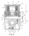
- Figure 9 is a partially cross sectioned view of the turbomolecular pump illustrated in Figures 4 to 6.
-
- The basic concept exploited by the present invention to regulate the voltage supplied to the motor of a vacuum pump is that of providing means for periodically interrupting the drive signals in the feeding circuit of the vacuum pump motor in such a way as to modify the rms (root mean squared) value of at least one of the e.m.f.s (electromotive forces) forming the e.m.f. or voltage system generated by the control unit and feeding the motor.
- Since the rms value of an voltage is inversely proportional to the duration of the switched-off intervals, such rms value can be modified in a wide range by properly adjusting the duration of the switching intervals.
- Therefore the effect that can be obtained on the motor working is similar to the effect that could be achieved through more complex direct regulation of the voltage values.
- In a preferred embodiment in which the vacuum pump is equipped with a three-phase A.C. asynchronous motor, the three-phase system of square-wave voltages for feeding the motor of the vacuum pump is generated by the circuit disclosed in details hereinbelow with reference to Figures 1, 2 and 3a to 3g.
- The circuit illustrated in Figure 1 substantially comprises a
microprocessor 200 connected to threeAND gates IC gate drivers microprocessor 200 and the other to the output of one of the above AND gates, three pairs of transistors, e.g. of the MOSFET type, indicated by the references from 207 to 212. The two MOSFET transistors of each pair are connected in series with each other, with both the two transistor gates and the common junction terminals R, S, T of the series connection connected to as many outputs of the corresponding AND gate. For each transistor pair one of the remaining terminals (the source oftransistor 208 in Fig. 1) is connected to a D.C. supply voltage while the other (the drain of transistor 207) is grounded. The D.C. voltage is obtained through adiode bridge 213 properly connected to the mains. - Through the
diode bridge 213 the alternating current from the mains is rectified and directly applied, i.e. without any intermediate voltage regulator, across the series connection of each pair of the sixMOSFET transistors 207 to 212. - Under the control of the
gate drivers MOSFET transistors 207 to 212 generates one of the voltages of a three-phase system to feed the three-phase asynchronous motor of the vacuum pump. - Figure 2 illustrates the signals A, B, D, E, G, H, generated by
microprocessor 200 for driving theMOSFET transistors 207 to 212 through thegate drivers - Signals B, E and H, are shown as negative since they relate to "low" inputs of the
gate drivers - The frequency of said signals A, B, D, E, G and H, corresponds to the excitation frequency of the asynchronous motor driving the vacuum pump.
- The
microprocessor 200 further generates a PWM signal, formed by pulses having a constant frequency and duration capable of being modulated, which signal is applied to the second input of eachAND gates - The enlarged detailed view of Figure 2 illustrates the widths or durations of said PWM signal when modulated by pulses having widths d, d' or d'', respectively.
- Each of the waveforms C, F and I in Figure 2 show the signals at the outputs of
AND gates - As shown in Fig. 2, the signals C, F and I are intermittent, i.e. formed by spaced bursts or trains of pulses with the duration of the burst corresponding to the time the signals A, D or G respectively is high, and the spacing to the time for which such signals are low. Signals C, F and I are applied to one input of the
gate drivers - This way between each pair of terminals R-S, S-T and T-R there will be generated the square wave signals C, F and I of Fig. 2, respectively, that are out of phase by 120° from each other and intermittent, i.e. formed by spaced bursts or trains of pulses with the duration of the burst corresponding to the time the signals A, D or G respectively is high, and the spacing to the time for which such signals are low. Signals C, F and I are applied to one input of the
gate drivers - Therefore the rms voltage of said three-phase voltage system will be proportional to the pulse width of the PWM signal generated by the
microprocessor 200. - The frequency of the PWM signal is generally selected in the range between 5 and 20 times the excitation frequency of the asynchronous motor.
- Since the power dissipated in the
MOSFET transistors 207 to 213 mainly depends on the number of their ON/OFF switchings, and since it is sufficient to cut off only one MOSFET transistor in each pair ofMOSFET transistors 207 to 213 to block the flow of the feeding current to each of the terminals R, S and T, in order to reduce the heat generation, then the pulsating signal PWM is combined only with the signals driving one transistor of each pair of theMOSFET transistors 207 to 213. - A voltage duplicating device can be provided in the network feeding line for extending the working range of the electronic control unit from about 90 to 260 V a.c.
- Therefore, by selecting an asynchronous motor capable of supplying the rated power at about 180 V A.C., it is possible to accomodate variations of the power distributing network voltage and to appreciably increase the efficiency of the electric motor with respect to the traditional low voltage motors, typically working at 50 V A.C.
- Figures 3a to 3g show the real waveforms of some of the most significant signals in the circuit of Figure 1 at different rotation speeds of an asynchronous motor driving the vacuum pump.
- More particularly, Figure 3a relates to a steady state rotation of the vacuum pump motor at 21,000 rpm, Figure 3b to a steady state rotation at 24,000 rpm, Figure 3c to a steady state rotation at 62,000 rpm, Figure 3d to a steady state rotation at 62,000 rpm, Figure 3e to a steady state rotation at 13,000 rpm, Figure 3f to a steady state rotation at 60,000 rpm, Figure 3g to a steady state rotation at 62,000 rpm.
- Advantageously the above described circuit can be equipped with means that are known to the skilled in the art for other types of motors that drive vacuum pumps, such as for example motors of the "brushless" type (without brushes) or "switched reluctance" (S.R.) motors.
- When using "brushless" and S.R. motors, the frequency of the PWM signal must vary as a function of the rotor position and therefore a return signal has to be provided that contains information relating to the rotor position in the motor.
- This signal is processed by the
microprocessor 200 and supplied, for example, to an optical or magnetic position sensor provided in the motor (not shown in the drawings). - The principle exploited in the above illustrated preferred embodiment - based on the presence of the PWM pulsating signal to activate and deactivate at least one of the motor driving signals - can be used with advantage also in different arrangements that are easily conceivable by the average skilled in the art.
- As an example, a first alternative embodiment of the control unit of the present invention can generate the voltage system and regulate the feeding voltage by using a small insulating transformer fed by the network voltage that has been rectified and modulated at high frequency, typically 100 kHz, with a mean value equal to zero. The voltage across the secondary winding of such small transformer is rectified again, filtered and used to drive transistors that feed the vacuum pump motor. The value of the motor drive voltage can be regulated by varying the rms voltage of the high frequency signal feeding the primary winding of the small transformer through the combination of a PWM signal in accordance with the principle described in the preferred embodiment.
- In this second embodiment the dimensions of the transformer can be reduced to a minimum since the operating frequency is high.
- In accordance with a further alternative embodiment of the control unit of the present invention, the voltage system and the regulation of the feeding voltage are accomplished through an L-C filtering group with a recirculation diode fed by the distribution network voltage that has been rectified and modulated at high frequency with a mean value different from zero.
- The regulation of the drive voltage for the motor is obtained by varying the "duty cycle" of the high frequency voltage applied the L-C filtering group through the combination of a PWM signal in accordance with the principle described in the preferred embodiment.
- With reference to Figures 4 to 9, the electronic control unit of the present invention, indicated as a whole by
reference 1, is integrated in a turbomolecular pump, indicated as a whole byreference 100. - As better shown in Figure 9, the
turbomolecular pump 100 comprises a substantiallycylindrical casing 101, having afirst portion 102 and asecond portion 103, coaxial to the former and with a smaller section. - The
first portion 102 houses the gas pumping stages and is provided with anaxial suction port 119 at one end and aradial exhaust port 120 at the opposed end, while thesecond portion 103 houses the motor and the support bearings for the shaft of theturbomolecular pump 100. - A plurality of
annular grooves 104 defining a series of cooling fins or rings 105 is provided on the outer surface of the firstlarger portion 102 of thecasing 101. - Additionally, on said outer surface of said first
larger portion 102 of thecasing 101 there are formed threelongitudinal grooves 106, spaced by 120° and adapted to allow the fitting of asmany fastening screws 107 for securing thepump 101 to theelectronic control unit 1. -
Annular grooves 108, defining a series of cooling rings 109 are also provided on the outer surface of the secondsmaller portion 103 of thecasing 101. - The
turbomolecular pump 100 is further provided with an annular protruding ring orflange 110 with peripherally spacedholes 117 for securing theturbomolecular pump 100 to the vessel or chamber (not shown) in which vacuum is to be created. - On the side opposed with respect to the
flange 110, in correspondence of the basis of said secondsmaller portion 103 of thecasing 101, there is provided acylindrical extension 118 due to the presence within thepump 100 of the bearings and the motor. - Still with reference to the Figure 9, the
turbomolecular pump 100 comprises amonolithic rotor 112 in which there are formedrotor disks 113 having flat surfaces androtor disks 114 equipped with blades. - Said
rotor disks - With reference again to Figures 4 to 8, the
control unit 1 comprises ahousing 2 having alower resting surface 3, anupper closure surface 4, andside - The
side 6 comprises a roundedportion 12 and twolinear portions 13, substantially parallel to each other. - The
upper closure surface 4 is provided with acircular opening 16 for the passagge of thesecond portion 103 of the already discussedcylindrical casing 101. - The
second portion 103 is therefore completely housed inside the space provided in thecasing 2, while thefirst portion 102 of saidcylindrical casing 101 is outside thecasing 2. - In the rounded
portion 12 of thecasing side 6 there are provided slots 9 whereas on the substantiallyopposed side 5 of thecasing 2 there is provided anopening 7, covered by a net or grid 8. A cooling air flow enters thehousing 2 through the slots 9, passes through thecasing 2 and comes out through the opening 8. - In the
side 5 there are further provided aremovable cap 10 for accessing to a device safety fuse (not shown), a sealingring 11 for the passage of thesupply cable 50 comprising a plurality of leads to theelectronic control unit 1, andconnectors unit 1 by means of an external unit (not shown), if required. - The
electronic control unit 1 further comprises leads 60 (Fig. 7) for feeding the three-phase asynchronous motor of thevacuum pump 100. - The air flow passing through the
casing 2 is obtained through a coolingfan 54 located internally to thecasing 2, in correspondence of theopening 7 in theside 5. - Inside the
casing 2 there are further housed the electronic components of theelectronic control unit 1. - More particularly, in order to house all the electronic components in the
casing 2 of thelower section portion 103 of thecasing 101, most of such components are substantially carried by two main (printed circuit)boards casing 2 and parallel to theface 3, and the second one being near and parallel to one of thestraight portions 13 of theside 6. - A thermistor 57 is mounted on said
board 56, substantially positioned at the center of the lowercircular opening 16 of thecasing 2 for the passage of thesecond portion 103 of thecylindrical casing 101, whith the surface of the thermistor 57 substantially in contact with thecylindrical extension 118, i.e the extension due to the presence, inside the thepump 100, of the bearings and of the pump motor, when thepump 100 is fitted into saidcasing 2. - In order to improve the thermal contact between the surface of the thermistor 57 and the
cylindrical extension 118, a resin layer 58 is interposed between the surface of the thermistor 57 and thecylindrical extension 118. - A
metal plate 59 is further provided inside thecasing 2, parallel to one of thestraight portion 13 of theside 6, opposed to theboard 55 with respect to the thermistor 57. - The function of the
metal plate 59 is to act as a heat sink of the heat generated by the sixMOSFET transistors 207 to 212 that are mounted on both surfaces of saidmetal plate 59 and in thermal contact therewith. The plate is located in a space subjected to the flow of cooling air entering through the slots 9 of thecasing 2 and coming out from theopening 7 on the opposed side of thecasing 2. - Therefore this air flow cools both the cooling rings 109 formed in the
second portion 103 of thecasing 101 of thepump 100 housed in saidcasing 2, and the electronic components of theelectronic control unit 1. - Thanks to the position of the thermistor 57 with respect to the three pairs of power dissipating components formerd by the
MOSFET transistors 207 to 212 and to the portion of the vacuum pump housing pump components that are at the highest temperature, only a single thermistor is used for controlling the temperatures of the pump and of the most critical electronic components of theelectronic control unit 1. - The temperature of the
MOSFET transistors 207 to 212 is directly measured through the value of electric resistance of the thermistor 57 that is related to the average temperature between the pump and the MOSFET transistors. - On the other hand, a measure of the temperature of the pump bearings is obtained by combining the temperature information supplied by the thermistor 57 with the information relating to the power absorbed by the pump, by using the following relationship:
- As better shown in the plane view of Figure 8 the
casing 2 of theelectronic control unit 1 has a substantially rounded shape and is substantially contained within the overall dimensions of theturbomolecular pump 100. - Thus the device integrating both the
turbomolecular pump 100 and theelectronic control unit 1 has reduced dimensions with respect to the traditional arrangements in which the pump and the control unit are provided as separate devices. - An additional advantage of integrating the electronic control unit in the turbomolecular pump is that the same air flow passing through the
casing 2 for cooling the electronic circuits housed inside thecasing 2, can be used for cooling the secondlower portion 103. - Further by integrating the
control unit 1 with theturbomolecular pump 100 the length of the feeding leads 60 located between the feeding electronic unit and theturbomolecular pump 100 is reduced to a minimum.
Claims (21)
- Combination of a vacuum pump, an electric motor and an electronic control unit (1), said unit (1) comprising:a casing (2);a first plurality of leads (50) for electrically feeding said control unit;a second plurality of leads (60) for electrically feeding said motor of the vacuum pump (100);a circuit for generating a voltage system adapted to feed said electric motor of the vacuum pump (100), said circuit providing for a plurality of drive signals for controlling the generation of said voltage system, said drive signals including at least one pulsating signal (PWM) the pulse width of which can be modulated, said circuit including means for combining said at least one modulated pulsating signal (PWM) with at least another one (A, D, G) of said drive signals in said circuit, characterized in that said at least one of the other drive signals is a pulsating signal and in that the signal originated from said combination is an intermittent signal of spaced bursts or trains of pulses, whereby the rms voltage of at least one voltage of said voltage system is modified proportionally to the width of said modulated pulsating signal(PWM).
- Combination as claimed in claim 1, characterized in that said at least one of the other drive signals (A, D, G) with which said at least one modulated pulsating signal (PWM) is combined has a frequency corresponding to the excitation frequency of said electric motor of the vacuum pump.
- Combination as claimed in claim 1 or 2, wherein said circuit voltage generating system comprises a microprocessor (200) generating a plurality of drive signals (A, B, D, E, G, H) controlling, through gate driver circuits (204, 205, 206), a plurality of discrete power components (207-212), each comprising a pair of said MOSFET transistors (207, 208; 209, 210; 211, 212) for each voltage of said voltage system.
- Combination as claimed in claim 3, wherein also said pulsating signal (PWM) is generated by said microprocessor (200), and said combining means comprises a plurality of logic gates (201, 202, 203), with said pulsating signal (PWM) being applied to the first input of each logic gate, and one of said drive signals (A, D, G) being applied to the second input of said logic gates (201, 202, 203), whereby said logic gates (201, 202, 203) periodically interrupt/activate said at least one drive signal (A, D, G) in correspondence of the pulses of said pulsating signal (PWM).
- Combination as claimed in claim 4 wherein said logic gates (201, 202, 203) are AND logic gates.
- Combination as claimed in claim 3 wherein at least one of said MOSFET transistors in each pair of MOSFET transistors (207, 208; 209, 210; 211, 212) is driven by one of the drive signals (A, D, G) that is generated by said microprocessor (200) and periodically interrupted-activated in correspondence of the HIGH/LOW states of said pulsating signal (PWM).
- Combination as claimed in claim 4 wherein said electric motor is a polyphase asynchronous motor, and wherein said voltage system adapted to feed the motor of the vacuum pump (100) is a square wave polyphase system.
- Combination as claimed in claim 4 wherein said electric motor is a D.C. "brushless" motor, and wherein said voltage system adapted to feed the motor of the vacuum pump (100) is a square wave polyphase system.
- Combination as claimed in claim 4 wherein said electric motor is a switched reluctance (S.R.) motor, and wherein said voltage system adapted to feed the motor of the vacuum pump (100) is a square wave polyphase system.
- Combination as claimed in claim 7 wherein the frequency of said pulsating signal (PWM) is comprised between 5 and 20 times the excitation frequency of said polyphase asynchronous motor.
- Combination as claimed in claims 8 or 9, wherein the frequency of said pulsating signal (PWM) varies as a funtion of the rotor position in the motor of the vacuum pump (100), the information relating the rotor position being supplied to the microprocessor (200) by a position sensor incorporated in the motor.
- Combination as claimed in any of the preceding claims wherein a space is provided in said casing (2) for receiving at least a portion (103) of said casing (101) of the vacuum pump (100).
- Combination as claimed in claim 12 wherein said at least one portion (103) of the casing (101) housed in said space corresponds to the portion of vacuum pump containing the electric motor of the vacuum pump and at least a support bearing of the rotatable shaft of said motor.
- Combination as claimed in claim 13 wherein said second plurality of leads (60) is completely contained inside said casing (2).
- Combination as claimed in claim 12 wherein a fan (54) is provided for generating a flow of cooling air within said casing (2), said flow of cooling air cooling at the same time the outer surface of said portion (103) of the casing (101) housed in said casing (2), and the electronic components present in said casing (2).
- Combination as claimed in claim 15 wherein in said casing (2) a first plurality of inlet openings (9) is provided for the inlet of the air sucked by said fan (54) and an opening (7) for the outlet of the air blown by said fan, said plurality of inlet openings (9) and said outlet opening (7) being located on reciprocally opposed sides (12, 5) of said casing (2).
- Combination as claimed in claim 12 wherein a metal plate (59) is provided as a heat sink that cooperates with the air flow generated by said fan (54) for dissipating the heat generated by said electronic power components (207-212) in said circuits, said power components (207-212) being located on and in thermal contact with both surfaces of said metal plate (59).
- Combination as claimed in claim 12 wherein a thermistor (57) is provided for sensing the temperatures of said pump (100) and of said electronic power components (207-212) inside said casing (2), said thermistor being located within the casing (2) in contact with the surface of said portion (103) of the casing (101) housed in said casing (2).
- Combination as s claimed in claim 18 wherein the value of the elettric resistance of said thermistor (57) is proportional to the mean value between the temperatures of the support bearings of the vacuum pump (100) and said electronic power components (207-212).
- Combination as claimed in claim 13 wherein said electronic components housed in said casing (2) are substantially distributed about the portion (103) of said casing (101) containing the bearings and the motor of the vacuum pump (100).
- Combination as claimed in any of the preceding claims, characterized in that said vacuum pump (100) is a turbomolecular vacuum pump provided with a suction port (119), an exhaust port (120) and a plurality of pumping stages formed by rotor disks (113, 114) secured to a pump rotatable shaft (13) driven by said electric motor, and stator rings (115, 116) secured to said pump casing (101) and cooperating with said rotor disks (113, 114).
Applications Claiming Priority (2)
| Application Number | Priority Date | Filing Date | Title |
|---|---|---|---|
| ITTO960822 | 1996-10-08 | ||
| IT96TO000822A IT1288738B1 (en) | 1996-10-08 | 1996-10-08 | ELECTRONIC CONTROL UNIT FOR VACUUM PUMP. |
Publications (3)
| Publication Number | Publication Date |
|---|---|
| EP0836009A2 EP0836009A2 (en) | 1998-04-15 |
| EP0836009A3 EP0836009A3 (en) | 1998-08-12 |
| EP0836009B1 true EP0836009B1 (en) | 2000-05-03 |
Family
ID=11414945
Family Applications (1)
| Application Number | Title | Priority Date | Filing Date |
|---|---|---|---|
| EP97109536A Revoked EP0836009B1 (en) | 1996-10-08 | 1997-06-12 | Vacuum pump in combination with an electronic control unit |
Country Status (5)
| Country | Link |
|---|---|
| US (1) | US5940576A (en) |
| EP (1) | EP0836009B1 (en) |
| JP (1) | JPH10150791A (en) |
| DE (1) | DE69701845T2 (en) |
| IT (1) | IT1288738B1 (en) |
Families Citing this family (11)
| Publication number | Priority date | Publication date | Assignee | Title |
|---|---|---|---|---|
| DE10114969A1 (en) * | 2001-03-27 | 2002-10-10 | Leybold Vakuum Gmbh | Turbo molecular pump |
| DE10215896A1 (en) * | 2002-04-11 | 2003-10-23 | Leybold Vakuum Gmbh | vacuum pump |
| US7361844B2 (en) * | 2002-11-25 | 2008-04-22 | Vlt, Inc. | Power converter package and thermal management |
| US7508156B2 (en) * | 2006-04-04 | 2009-03-24 | A. O. Smith Corporation | Electrical machine having a series chopper circuit |
| JP5024507B2 (en) * | 2006-04-12 | 2012-09-12 | 株式会社島津製作所 | Turbo molecular pump and vacuum device |
| EP2104221A1 (en) * | 2008-03-22 | 2009-09-23 | Grundfos Management A/S | Method for controlling a multi-phase electromotor operated in a star circuit |
| JP2014147170A (en) * | 2013-01-28 | 2014-08-14 | Shimadzu Corp | Motor drive for vacuum pump and vacuum pump |
| EP2846043B1 (en) * | 2013-09-09 | 2020-01-22 | Leybold GmbH | Calculation of the rotor temperature of a vacuum pump using the motor current or power |
| US20150330397A1 (en) * | 2014-05-14 | 2015-11-19 | International Business Machines Corporation | Air flow detection and correction based on air flow impedance |
| JP7022265B2 (en) * | 2017-10-25 | 2022-02-18 | 株式会社島津製作所 | Vacuum pump |
| JP7087418B2 (en) * | 2018-02-02 | 2022-06-21 | 株式会社島津製作所 | Vacuum pump |
Family Cites Families (16)
| Publication number | Priority date | Publication date | Assignee | Title |
|---|---|---|---|---|
| JPS5928146B2 (en) * | 1978-11-04 | 1984-07-11 | ファナック株式会社 | Induction motor drive control method |
| US5443368A (en) * | 1993-07-16 | 1995-08-22 | Helix Technology Corporation | Turbomolecular pump with valves and integrated electronic controls |
| US4897023A (en) * | 1988-11-28 | 1990-01-30 | Milton Roy Company | Liquid pump assembly |
| US5238362A (en) * | 1990-03-09 | 1993-08-24 | Varian Associates, Inc. | Turbomolecular pump |
| IT1241431B (en) * | 1990-03-09 | 1994-01-17 | Varian Spa | PERFECTED TURBOMOLECULAR PUMP. |
| TR26731A (en) * | 1990-10-10 | 1995-05-15 | Icotron Sa | ASSEMBLY FOR THE IMPLEMENTATION OF A METHOD AND METHOD FOR DETERMINING THE LOAD STATUS OF A NON-STIMULATED MOTOR FEEDED BY A FREQUENCY REGULATOR. |
| DE4113068A1 (en) * | 1991-04-22 | 1992-11-05 | Leybold Ag | Ascertaining or regulating RPM of async. motor - altering frequency of variable voltage or current source until characteristic signal indicates switching between motor and generator modes |
| JPH0529073A (en) * | 1991-07-24 | 1993-02-05 | Matsushita Electric Ind Co Ltd | Induction heating cooker |
| JP2976633B2 (en) * | 1991-10-21 | 1999-11-10 | 松下電器産業株式会社 | Induction heating cooker |
| JP2994150B2 (en) * | 1992-07-30 | 1999-12-27 | 日本電産株式会社 | Fan motor |
| DE4237971B4 (en) * | 1992-11-11 | 2004-05-06 | Unaxis Deutschland Holding Gmbh | Vacuum pump with converter |
| JPH07154976A (en) * | 1993-11-30 | 1995-06-16 | Fuji Electric Co Ltd | How to operate the inverter cooling fan |
| DE4410903A1 (en) * | 1994-03-29 | 1995-10-05 | Leybold Ag | System with vacuum pump, measuring device as well as supply, control, operating and display devices |
| JPH0828471A (en) * | 1994-07-11 | 1996-01-30 | Matsushita Electric Ind Co Ltd | Positive displacement pump |
| JPH0835713A (en) * | 1994-07-26 | 1996-02-06 | Fujitsu General Ltd | Air conditioner control method and device |
| DE9417422U1 (en) * | 1994-10-31 | 1995-02-09 | Leybold AG, 50968 Köln | Friction vacuum pump with housing |
-
1996
- 1996-10-08 IT IT96TO000822A patent/IT1288738B1/en active IP Right Grant
-
1997
- 1997-06-12 EP EP97109536A patent/EP0836009B1/en not_active Revoked
- 1997-06-12 DE DE69701845T patent/DE69701845T2/en not_active Revoked
- 1997-10-07 US US08/946,430 patent/US5940576A/en not_active Expired - Fee Related
- 1997-10-08 JP JP9290525A patent/JPH10150791A/en active Pending
Also Published As
| Publication number | Publication date |
|---|---|
| ITTO960822A1 (en) | 1998-04-08 |
| IT1288738B1 (en) | 1998-09-24 |
| US5940576A (en) | 1999-08-17 |
| EP0836009A3 (en) | 1998-08-12 |
| DE69701845D1 (en) | 2000-06-08 |
| DE69701845T2 (en) | 2000-11-16 |
| JPH10150791A (en) | 1998-06-02 |
| EP0836009A2 (en) | 1998-04-15 |
Similar Documents
| Publication | Publication Date | Title |
|---|---|---|
| EP0836008B1 (en) | A vacuum pumping device | |
| US5770909A (en) | Wound rotor synchronous motor-generator and field control system therefor | |
| US5763969A (en) | Integrated electric motor and drive system with auxiliary cooling motor and asymmetric heat sink | |
| EP0836009B1 (en) | Vacuum pump in combination with an electronic control unit | |
| US7281908B2 (en) | Electrically powered blower with improved heat dissipation | |
| KR940010066B1 (en) | Brushless motor incorporating an integrated circuit having a 0ne-chipped peripheral circuit | |
| US6208113B1 (en) | System for controlling the rotation of AC motors | |
| CN101159396A (en) | Converter motor | |
| KR100786433B1 (en) | Brushless dc motor coupled directly to ac source and electric apparatus using the same motor | |
| JP2001251886A (en) | Motor driving circuit, motor driving method, and semiconductor integrated circuit device | |
| CN101179247B (en) | Motor drive circuit, motor drive method, and semiconductor integrated circuit device | |
| US6433507B1 (en) | Spread spectrum motor control circuit | |
| US5537015A (en) | Semiconductor circuit for a DC motor | |
| US20250350162A1 (en) | Motor assembly for driving a pump with a matrix converter | |
| US4516912A (en) | Compressor arrangement for a heat pump installation | |
| US7317296B2 (en) | Electric motor | |
| US11848619B2 (en) | Apparatus and methods for supplying DC power to control circuitry of a matrix converter | |
| JPH10174276A (en) | Motor protection device | |
| JP2598263Y2 (en) | Electrical machinery for vehicles | |
| JPH0763321A (en) | Water heater | |
| WO1997015111A3 (en) | A brushless dc motor assembly | |
| US11799404B1 (en) | Motor controller circuit having rotational speed locking mechanism | |
| CA3168095C (en) | Apparatus and methods for supplying dc power to control circuitry of a matrix converter | |
| SU1749986A1 (en) | Synchronous brush generator | |
| EP3796543B1 (en) | Method for operating a brushed direct current electric motor, data processing apparatus, computer program, computer-readable data carrier and a device |
Legal Events
| Date | Code | Title | Description |
|---|---|---|---|
| PUAI | Public reference made under article 153(3) epc to a published international application that has entered the european phase |
Free format text: ORIGINAL CODE: 0009012 |
|
| AK | Designated contracting states |
Kind code of ref document: A2 Designated state(s): DE FR GB IT |
|
| AX | Request for extension of the european patent |
Free format text: AL;LT;LV;RO;SI |
|
| PUAL | Search report despatched |
Free format text: ORIGINAL CODE: 0009013 |
|
| AK | Designated contracting states |
Kind code of ref document: A3 Designated state(s): AT BE CH DE DK ES FI FR GB GR IE IT LI LU MC NL PT SE |
|
| AX | Request for extension of the european patent |
Free format text: AL;LT;LV;RO;SI |
|
| 17P | Request for examination filed |
Effective date: 19980916 |
|
| 17Q | First examination report despatched |
Effective date: 19981222 |
|
| AKX | Designation fees paid |
Free format text: DE FR GB IT |
|
| RBV | Designated contracting states (corrected) |
Designated state(s): DE FR GB IT |
|
| GRAG | Despatch of communication of intention to grant |
Free format text: ORIGINAL CODE: EPIDOS AGRA |
|
| RTI1 | Title (correction) |
Free format text: VACUUM PUMP IN COMBINATION WITH AN ELECTRONIC CONTROL UNIT |
|
| GRAG | Despatch of communication of intention to grant |
Free format text: ORIGINAL CODE: EPIDOS AGRA |
|
| GRAH | Despatch of communication of intention to grant a patent |
Free format text: ORIGINAL CODE: EPIDOS IGRA |
|
| GRAH | Despatch of communication of intention to grant a patent |
Free format text: ORIGINAL CODE: EPIDOS IGRA |
|
| GRAA | (expected) grant |
Free format text: ORIGINAL CODE: 0009210 |
|
| AK | Designated contracting states |
Kind code of ref document: B1 Designated state(s): DE FR GB IT |
|
| REF | Corresponds to: |
Ref document number: 69701845 Country of ref document: DE Date of ref document: 20000608 |
|
| ITF | It: translation for a ep patent filed | ||
| ET | Fr: translation filed | ||
| PLBQ | Unpublished change to opponent data |
Free format text: ORIGINAL CODE: EPIDOS OPPO |
|
| PLBI | Opposition filed |
Free format text: ORIGINAL CODE: 0009260 |
|
| PLBQ | Unpublished change to opponent data |
Free format text: ORIGINAL CODE: EPIDOS OPPO |
|
| PLBI | Opposition filed |
Free format text: ORIGINAL CODE: 0009260 |
|
| PLBF | Reply of patent proprietor to notice(s) of opposition |
Free format text: ORIGINAL CODE: EPIDOS OBSO |
|
| 26 | Opposition filed |
Opponent name: PFEIFFER VACUUM GMBH Effective date: 20010124 |
|
| 26 | Opposition filed |
Opponent name: LEYBOLD VAKUUM GMBH Effective date: 20010131 Opponent name: PFEIFFER VACUUM GMBH Effective date: 20010124 |
|
| PLBF | Reply of patent proprietor to notice(s) of opposition |
Free format text: ORIGINAL CODE: EPIDOS OBSO |
|
| REG | Reference to a national code |
Ref country code: GB Ref legal event code: IF02 |
|
| RDAF | Communication despatched that patent is revoked |
Free format text: ORIGINAL CODE: EPIDOSNREV1 |
|
| APBP | Date of receipt of notice of appeal recorded |
Free format text: ORIGINAL CODE: EPIDOSNNOA2O |
|
| APBQ | Date of receipt of statement of grounds of appeal recorded |
Free format text: ORIGINAL CODE: EPIDOSNNOA3O |
|
| APAA | Appeal reference recorded |
Free format text: ORIGINAL CODE: EPIDOS REFN |
|
| APAH | Appeal reference modified |
Free format text: ORIGINAL CODE: EPIDOSCREFNO |
|
| APAH | Appeal reference modified |
Free format text: ORIGINAL CODE: EPIDOSCREFNO |
|
| PGFP | Annual fee paid to national office [announced via postgrant information from national office to epo] |
Ref country code: FR Payment date: 20060428 Year of fee payment: 10 |
|
| PGFP | Annual fee paid to national office [announced via postgrant information from national office to epo] |
Ref country code: DE Payment date: 20060505 Year of fee payment: 10 |
|
| PGFP | Annual fee paid to national office [announced via postgrant information from national office to epo] |
Ref country code: GB Payment date: 20060629 Year of fee payment: 10 |
|
| PGFP | Annual fee paid to national office [announced via postgrant information from national office to epo] |
Ref country code: IT Payment date: 20060630 Year of fee payment: 10 |
|
| APBU | Appeal procedure closed |
Free format text: ORIGINAL CODE: EPIDOSNNOA9O |
|
| RDAG | Patent revoked |
Free format text: ORIGINAL CODE: 0009271 |
|
| STAA | Information on the status of an ep patent application or granted ep patent |
Free format text: STATUS: PATENT REVOKED |
|
| 27W | Patent revoked |
Effective date: 20070118 |
|
| GBPR | Gb: patent revoked under art. 102 of the ep convention designating the uk as contracting state |
Free format text: 20070118 |
|
| PLAB | Opposition data, opponent's data or that of the opponent's representative modified |
Free format text: ORIGINAL CODE: 0009299OPPO |
|
| R26 | Opposition filed (corrected) |
Opponent name: LEYBOLD VACUUM GMBH Effective date: 20010131 Opponent name: PFEIFFER VACUUM GMBH Effective date: 20010124 |