EP0838242B1 - Thermally responsive frangible bulb - Google Patents
Thermally responsive frangible bulb Download PDFInfo
- Publication number
- EP0838242B1 EP0838242B1 EP97307891A EP97307891A EP0838242B1 EP 0838242 B1 EP0838242 B1 EP 0838242B1 EP 97307891 A EP97307891 A EP 97307891A EP 97307891 A EP97307891 A EP 97307891A EP 0838242 B1 EP0838242 B1 EP 0838242B1
- Authority
- EP
- European Patent Office
- Prior art keywords
- liquid
- frangible bulb
- frangible
- thermally responsive
- bulb
- Prior art date
- Legal status (The legal status is an assumption and is not a legal conclusion. Google has not performed a legal analysis and makes no representation as to the accuracy of the status listed.)
- Expired - Lifetime
Links
- 239000007788 liquid Substances 0.000 claims description 38
- UHOVQNZJYSORNB-UHFFFAOYSA-N Benzene Chemical compound C1=CC=CC=C1 UHOVQNZJYSORNB-UHFFFAOYSA-N 0.000 claims description 12
- ZMXDDKWLCZADIW-UHFFFAOYSA-N N,N-Dimethylformamide Chemical compound CN(C)C=O ZMXDDKWLCZADIW-UHFFFAOYSA-N 0.000 claims description 9
- 239000012530 fluid Substances 0.000 claims description 8
- 229910052736 halogen Inorganic materials 0.000 claims description 7
- ZPQOPVIELGIULI-UHFFFAOYSA-N 1,3-dichlorobenzene Chemical compound ClC1=CC=CC(Cl)=C1 ZPQOPVIELGIULI-UHFFFAOYSA-N 0.000 claims description 6
- 150000002367 halogens Chemical class 0.000 claims description 6
- 230000000979 retarding effect Effects 0.000 claims description 6
- 150000008431 aliphatic amides Chemical class 0.000 claims description 5
- 150000004945 aromatic hydrocarbons Chemical class 0.000 claims description 5
- 125000005843 halogen group Chemical group 0.000 claims description 5
- 125000004435 hydrogen atom Chemical group [H]* 0.000 claims description 4
- FXHOOIRPVKKKFG-UHFFFAOYSA-N N,N-Dimethylacetamide Chemical compound CN(C)C(C)=O FXHOOIRPVKKKFG-UHFFFAOYSA-N 0.000 claims description 3
- 239000000203 mixture Substances 0.000 claims description 3
- DVTULTINXNWGJY-UHFFFAOYSA-N 1-Bromo-2,4,5-trifluorobenzene Chemical compound FC1=CC(F)=C(Br)C=C1F DVTULTINXNWGJY-UHFFFAOYSA-N 0.000 claims description 2
- 150000001875 compounds Chemical class 0.000 claims description 2
- SCNOFCUSDSAHOM-UHFFFAOYSA-N formamide;n-methylformamide Chemical compound NC=O.CNC=O SCNOFCUSDSAHOM-UHFFFAOYSA-N 0.000 claims 1
- 239000011521 glass Substances 0.000 description 28
- 230000004044 response Effects 0.000 description 15
- 229910000679 solder Inorganic materials 0.000 description 7
- LYCAIKOWRPUZTN-UHFFFAOYSA-N Ethylene glycol Chemical compound OCCO LYCAIKOWRPUZTN-UHFFFAOYSA-N 0.000 description 6
- 239000000126 substance Substances 0.000 description 6
- PEDCQBHIVMGVHV-UHFFFAOYSA-N Glycerine Chemical compound OCC(O)CO PEDCQBHIVMGVHV-UHFFFAOYSA-N 0.000 description 5
- 238000009835 boiling Methods 0.000 description 5
- ZHNUHDYFZUAESO-UHFFFAOYSA-N Formamide Chemical compound NC=O ZHNUHDYFZUAESO-UHFFFAOYSA-N 0.000 description 4
- CYTYCFOTNPOANT-UHFFFAOYSA-N Perchloroethylene Chemical compound ClC(Cl)=C(Cl)Cl CYTYCFOTNPOANT-UHFFFAOYSA-N 0.000 description 4
- 230000008901 benefit Effects 0.000 description 4
- VZGDMQKNWNREIO-UHFFFAOYSA-N tetrachloromethane Chemical compound ClC(Cl)(Cl)Cl VZGDMQKNWNREIO-UHFFFAOYSA-N 0.000 description 4
- RFFLAFLAYFXFSW-UHFFFAOYSA-N 1,2-dichlorobenzene Chemical compound ClC1=CC=CC=C1Cl RFFLAFLAYFXFSW-UHFFFAOYSA-N 0.000 description 3
- CSCPPACGZOOCGX-UHFFFAOYSA-N Acetone Chemical compound CC(C)=O CSCPPACGZOOCGX-UHFFFAOYSA-N 0.000 description 3
- 229950011008 tetrachloroethylene Drugs 0.000 description 3
- QPFMBZIOSGYJDE-UHFFFAOYSA-N 1,1,2,2-tetrachloroethane Chemical compound ClC(Cl)C(Cl)Cl QPFMBZIOSGYJDE-UHFFFAOYSA-N 0.000 description 2
- WQONPSCCEXUXTQ-UHFFFAOYSA-N 1,2-dibromobenzene Chemical compound BrC1=CC=CC=C1Br WQONPSCCEXUXTQ-UHFFFAOYSA-N 0.000 description 2
- PAYRUJLWNCNPSJ-UHFFFAOYSA-N Aniline Chemical compound NC1=CC=CC=C1 PAYRUJLWNCNPSJ-UHFFFAOYSA-N 0.000 description 2
- ATHHXGZTWNVVOU-UHFFFAOYSA-N N-methylformamide Chemical compound CNC=O ATHHXGZTWNVVOU-UHFFFAOYSA-N 0.000 description 2
- 238000004458 analytical method Methods 0.000 description 2
- 238000013459 approach Methods 0.000 description 2
- 230000015572 biosynthetic process Effects 0.000 description 2
- DIKBFYAXUHHXCS-UHFFFAOYSA-N bromoform Chemical compound BrC(Br)Br DIKBFYAXUHHXCS-UHFFFAOYSA-N 0.000 description 2
- 238000005755 formation reaction Methods 0.000 description 2
- 235000011187 glycerol Nutrition 0.000 description 2
- 238000004519 manufacturing process Methods 0.000 description 2
- 239000000463 material Substances 0.000 description 2
- 238000011160 research Methods 0.000 description 2
- 230000035945 sensitivity Effects 0.000 description 2
- 230000008542 thermal sensitivity Effects 0.000 description 2
- 230000001988 toxicity Effects 0.000 description 2
- 231100000419 toxicity Toxicity 0.000 description 2
- 238000011144 upstream manufacturing Methods 0.000 description 2
- UOCLXMDMGBRAIB-UHFFFAOYSA-N 1,1,1-trichloroethane Chemical compound CC(Cl)(Cl)Cl UOCLXMDMGBRAIB-UHFFFAOYSA-N 0.000 description 1
- JSRLURSZEMLAFO-UHFFFAOYSA-N 1,3-dibromobenzene Chemical compound BrC1=CC=CC(Br)=C1 JSRLURSZEMLAFO-UHFFFAOYSA-N 0.000 description 1
- XPBKEVCFKWTLHO-UHFFFAOYSA-N 1,3-dichloro-2,5-difluorobenzene Chemical compound FC1=CC(Cl)=C(F)C(Cl)=C1 XPBKEVCFKWTLHO-UHFFFAOYSA-N 0.000 description 1
- WNXJIVFYUVYPPR-UHFFFAOYSA-N 1,3-dioxolane Chemical compound C1COCO1 WNXJIVFYUVYPPR-UHFFFAOYSA-N 0.000 description 1
- QBELEDRHMPMKHP-UHFFFAOYSA-N 1-bromo-2-chlorobenzene Chemical compound ClC1=CC=CC=C1Br QBELEDRHMPMKHP-UHFFFAOYSA-N 0.000 description 1
- IPWBFGUBXWMIPR-UHFFFAOYSA-N 1-bromo-2-fluorobenzene Chemical compound FC1=CC=CC=C1Br IPWBFGUBXWMIPR-UHFFFAOYSA-N 0.000 description 1
- JRGGUPZKKTVKOV-UHFFFAOYSA-N 1-bromo-3-chlorobenzene Chemical compound ClC1=CC=CC(Br)=C1 JRGGUPZKKTVKOV-UHFFFAOYSA-N 0.000 description 1
- AITNMTXHTIIIBB-UHFFFAOYSA-N 1-bromo-4-fluorobenzene Chemical compound FC1=CC=C(Br)C=C1 AITNMTXHTIIIBB-UHFFFAOYSA-N 0.000 description 1
- ZCJAYDKWZAWMPR-UHFFFAOYSA-N 1-chloro-2-fluorobenzene Chemical compound FC1=CC=CC=C1Cl ZCJAYDKWZAWMPR-UHFFFAOYSA-N 0.000 description 1
- RJCGZNCCVKIBHO-UHFFFAOYSA-N 1-chloro-4-fluorobenzene Chemical compound FC1=CC=C(Cl)C=C1 RJCGZNCCVKIBHO-UHFFFAOYSA-N 0.000 description 1
- JTXMVXSTHSMVQF-UHFFFAOYSA-N 2-acetyloxyethyl acetate Chemical compound CC(=O)OCCOC(C)=O JTXMVXSTHSMVQF-UHFFFAOYSA-N 0.000 description 1
- WKBOTKDWSSQWDR-UHFFFAOYSA-N Bromine atom Chemical compound [Br] WKBOTKDWSSQWDR-UHFFFAOYSA-N 0.000 description 1
- KULIRCYGWVDMTE-UHFFFAOYSA-N C.[I].[I] Chemical compound C.[I].[I] KULIRCYGWVDMTE-UHFFFAOYSA-N 0.000 description 1
- OKTJSMMVPCPJKN-UHFFFAOYSA-N Carbon Chemical compound [C] OKTJSMMVPCPJKN-UHFFFAOYSA-N 0.000 description 1
- ZAMOUSCENKQFHK-UHFFFAOYSA-N Chlorine atom Chemical compound [Cl] ZAMOUSCENKQFHK-UHFFFAOYSA-N 0.000 description 1
- HEDRZPFGACZZDS-UHFFFAOYSA-N Chloroform Chemical compound ClC(Cl)Cl HEDRZPFGACZZDS-UHFFFAOYSA-N 0.000 description 1
- XDTMQSROBMDMFD-UHFFFAOYSA-N Cyclohexane Chemical compound C1CCCCC1 XDTMQSROBMDMFD-UHFFFAOYSA-N 0.000 description 1
- LFQSCWFLJHTTHZ-UHFFFAOYSA-N Ethanol Chemical compound CCO LFQSCWFLJHTTHZ-UHFFFAOYSA-N 0.000 description 1
- PXGOKWXKJXAPGV-UHFFFAOYSA-N Fluorine Chemical compound FF PXGOKWXKJXAPGV-UHFFFAOYSA-N 0.000 description 1
- DGAQECJNVWCQMB-PUAWFVPOSA-M Ilexoside XXIX Chemical compound C[C@@H]1CC[C@@]2(CC[C@@]3(C(=CC[C@H]4[C@]3(CC[C@@H]5[C@@]4(CC[C@@H](C5(C)C)OS(=O)(=O)[O-])C)C)[C@@H]2[C@]1(C)O)C)C(=O)O[C@H]6[C@@H]([C@H]([C@@H]([C@H](O6)CO)O)O)O.[Na+] DGAQECJNVWCQMB-PUAWFVPOSA-M 0.000 description 1
- 239000002202 Polyethylene glycol Substances 0.000 description 1
- 108091027981 Response element Proteins 0.000 description 1
- 230000009471 action Effects 0.000 description 1
- 230000004913 activation Effects 0.000 description 1
- 125000003368 amide group Chemical group 0.000 description 1
- 150000001408 amides Chemical class 0.000 description 1
- 229940072049 amyl acetate Drugs 0.000 description 1
- PGMYKACGEOXYJE-UHFFFAOYSA-N anhydrous amyl acetate Natural products CCCCCOC(C)=O PGMYKACGEOXYJE-UHFFFAOYSA-N 0.000 description 1
- 125000003118 aryl group Chemical group 0.000 description 1
- 239000005388 borosilicate glass Substances 0.000 description 1
- GDTBXPJZTBHREO-UHFFFAOYSA-N bromine Substances BrBr GDTBXPJZTBHREO-UHFFFAOYSA-N 0.000 description 1
- 229910052794 bromium Inorganic materials 0.000 description 1
- 229950005228 bromoform Drugs 0.000 description 1
- 238000004364 calculation method Methods 0.000 description 1
- 229910052799 carbon Inorganic materials 0.000 description 1
- 125000003636 chemical group Chemical group 0.000 description 1
- 229910052801 chlorine Inorganic materials 0.000 description 1
- 239000000460 chlorine Substances 0.000 description 1
- 229960001701 chloroform Drugs 0.000 description 1
- 230000002596 correlated effect Effects 0.000 description 1
- 230000007423 decrease Effects 0.000 description 1
- 230000003247 decreasing effect Effects 0.000 description 1
- 238000011161 development Methods 0.000 description 1
- 238000009826 distribution Methods 0.000 description 1
- 230000000694 effects Effects 0.000 description 1
- 238000005516 engineering process Methods 0.000 description 1
- 230000007613 environmental effect Effects 0.000 description 1
- 239000002360 explosive Substances 0.000 description 1
- 229910052731 fluorine Inorganic materials 0.000 description 1
- 239000011737 fluorine Substances 0.000 description 1
- -1 for example Chemical compound 0.000 description 1
- 238000007710 freezing Methods 0.000 description 1
- 230000008014 freezing Effects 0.000 description 1
- 125000000524 functional group Chemical group 0.000 description 1
- 238000007496 glass forming Methods 0.000 description 1
- 231100000206 health hazard Toxicity 0.000 description 1
- MNWFXJYAOYHMED-UHFFFAOYSA-M heptanoate Chemical compound CCCCCCC([O-])=O MNWFXJYAOYHMED-UHFFFAOYSA-M 0.000 description 1
- 238000011068 loading method Methods 0.000 description 1
- 230000007774 longterm Effects 0.000 description 1
- 230000008018 melting Effects 0.000 description 1
- 238000002844 melting Methods 0.000 description 1
- QSHDDOUJBYECFT-UHFFFAOYSA-N mercury Chemical compound [Hg] QSHDDOUJBYECFT-UHFFFAOYSA-N 0.000 description 1
- 229910052753 mercury Inorganic materials 0.000 description 1
- 229910052751 metal Inorganic materials 0.000 description 1
- 239000002184 metal Substances 0.000 description 1
- 238000005058 metal casting Methods 0.000 description 1
- 150000002739 metals Chemical class 0.000 description 1
- 238000000034 method Methods 0.000 description 1
- 229920001223 polyethylene glycol Polymers 0.000 description 1
- 230000008092 positive effect Effects 0.000 description 1
- YGSFNCRAZOCNDJ-UHFFFAOYSA-N propan-2-one Chemical compound CC(C)=O.CC(C)=O YGSFNCRAZOCNDJ-UHFFFAOYSA-N 0.000 description 1
- 239000010453 quartz Substances 0.000 description 1
- 230000009467 reduction Effects 0.000 description 1
- 230000000630 rising effect Effects 0.000 description 1
- 238000007789 sealing Methods 0.000 description 1
- VYPSYNLAJGMNEJ-UHFFFAOYSA-N silicon dioxide Inorganic materials O=[Si]=O VYPSYNLAJGMNEJ-UHFFFAOYSA-N 0.000 description 1
- 229910052708 sodium Inorganic materials 0.000 description 1
- 239000011734 sodium Substances 0.000 description 1
- 238000012360 testing method Methods 0.000 description 1
- 238000012546 transfer Methods 0.000 description 1
- ZIBGPFATKBEMQZ-UHFFFAOYSA-N triethylene glycol Chemical compound OCCOCCOCCO ZIBGPFATKBEMQZ-UHFFFAOYSA-N 0.000 description 1
Images

Classifications
-
- A—HUMAN NECESSITIES
- A62—LIFE-SAVING; FIRE-FIGHTING
- A62C—FIRE-FIGHTING
- A62C37/00—Control of fire-fighting equipment
- A62C37/08—Control of fire-fighting equipment comprising an outlet device containing a sensor, or itself being the sensor, i.e. self-contained sprinklers
- A62C37/10—Releasing means, e.g. electrically released
- A62C37/11—Releasing means, e.g. electrically released heat-sensitive
- A62C37/14—Releasing means, e.g. electrically released heat-sensitive with frangible vessels
Definitions
- THIS INVENTION relates to a thermally responsive frangible bulb of the type used to automatically release quick response, fire protection sprinklers (nozzles) or, other types of thermally actuated devices.
- nozzles have a frame with an outlet at one end, an orifice which is usually just upstream of the outlet, and an inlet which is connectable to a source of fire retarding fluid under pressure.
- the outlet is secured in the normally closed or sealed position by a cap, the cap being held in place by a thermally responsive element which is releasable when its temperature is increased from a normal ambient condition to a value within a prescribed operating range, by the heat from a fire.
- a stream of fire retarding fluid rushes from the outlet towards a deflector, which is mounted on the frame at the opposite end from the outlet, and is distributed over the area to be protected by the sprinkler (nozzle) from fire.
- the two primary types of thermally responsive elements used to automatically release fire sprinklers are fusible solder links and frangible glass bulbs.
- Automatic fire sprinklers were first commercially introduced in the 1870's with various types of fusible solder links. Although ultimately satisfactory, a great deal of effort went into the development of the fusible solder links to ensure, among other requirements, that they would: not creep apart, over time, at the normally expected ambient temperature conditions; not be deteriorated or corroded by the normally expected environmental conditions; release with a sharp, positive action; be thrown free of the sprinkler upon activation, so as to not interfere with the distribution of the fire retarding fluid; and, respond promptly to fire conditions.
- frangible glass bulb elements not only addressed the above mentioned performance requirements for fusible solder links, and indeed for automatic fire sprinklers in general, at a low manufacturing cost for the thermally responsive element, they have also ultimately provided a ready means for automating the assembly of automatic fire sprinklers.
- frangible glass bulbs as thermally responsive elements for automatic fire sprinklers
- particular strength, thermophysical, shape and dimensional requirements for the glass shell which forms the exterior of the bulbs the need to have certain thermophysical properties for the liquid used to fill the glass shell; and the necessity for precise control over the extent to which the glass shell is filled with liquid prior to sealing.
- the bulb is initially filled with a liquid, the remaining space being largely a bubble.
- the liquid used has been chosen because of its low freezing point, large co-efficient of (thermal) expansion, slight compressibility, low specific heat and the reluctance with which it retains air in solution.
- the head fire sprinkler
- the liquid expands and gradually the bubble decreases in size, the air being forced into solution because of the increasing pressure and in spite of the elevated temperature.
- all of the air becomes dissolved and the entire bulb is filled with the expanding liquid.
- an almost irresistible internal force is brought to bear on the walls of the bulb and fracture soon occurs.
- the pressure is suddenly decreased so that the air which has been held in solution is free to escape with a mildly explosive action which is sufficient to completely shatter the bulb even in spite of heavy loadings (due to the sprinkler assembly).
- frangible glass bulb sprinkler since the invention of the frangible glass bulb sprinkler, various types of liquids have been used for filling the bulbs, such as: mercury, carbon tectrachloride, alcohol, tetrachloroethane, acetone, amyl acetate, triethylene glycol, glycol diacetate, ethylene glycol, glycerol, and other dielectric fluids commonly used for heat transfer applications.
- these types of fluids do not offer the combination of properties needed to achieve quick response operating characteristics as well as low Hazard Ratings in cost effective frangible glass bulbs having a nominal operating temperature rating of at least up to 93°C and, preferably at least up to 141°C.
- trichloromethane was used for the filling of quick response, frangible glass bulbs, but more recently liquids such as tetrachloroethylene (perchloroethylene) as described in U.S. Patent 4938294 have been used to fill bulbs having a nominal operating temperature rating of up to 93°C. Because the boiling point of the tetrachloroethylene liquid is about 121°C, it is not generally suitable for use in filling the subsequently developed quick response, frangible glass bulbs having a nominal operating temperature rating of up to 93°C.
- tetrachloroethylene perchloroethylene
- a thermally responsive frangible bulb comprising a shell defining a closed interior space containing a liquid which expands to fill the space and fracture the bulb when heated to within a pre-determined temperature range, wherein the liquid comprises at least one member from either of the chemical groups consisting of derivatives of aromatic hydrocarbons containing two or more halogen substituents and aliphatic amides.
- suitable liquids for fast response sprinkler bulbs has been based on consideration of thermophysical properties such as compressibility, thermal expansivity and thermal conductivity, for example as described in U.S. patent 4938294, the data available for candidate liquids is sparse, often dubious and rarely in the pressure/temperature regime of a sprinkler bulb at operation. It is not possible to accurately predict performance as a bulb filling liquid based on incomplete or contentious literature values. Practically no independent empirical measures exist of important liquid properties such as the dP/dT ratio which defines the relationship between bulb operating temperature and sensitivity. The choice of the most suitable liquid depends on an extensive empirical testing programme where the thermophysical factors outlined above will indicate, but not exclude candidate substances. Examples of liquids assessed by this approach are shown in Table 1.
- a preferred filling liquid comprises a member of the group of halogenated aromatic hydrocarbons containing two or more halogen substituents, or of the group of aliphatic amides.
- the halogenated aromatic hydrocarbon is benzene for which two or more hydrogens are substituted by a halogen, such as 1,3 dibromobenzene illustrated below.
- the above is an example of a Hückel aromatic hydrocarbon, containing 2n+2 ⁇ electrons, with two halogen groups bound directly to the aromatic ring.
- the halogen may be selected from bromine, chlorine or fluorine, for example, 1,2-dichlorobenzene, 1,3-dichlorobenzene, 1,2-dibromobenzene, 1-bromo-2-chlorobenzene, 1-bromo-2-fluorobenzene, 1-bromo-4-fluorobenzene, 1-chloro-2-fluorobenzene, 1-chloro-4-fluorobenzen, 1,2,4-dichlorobenzene, 1-bromo-2,4,5-trifluorobenzene, 1,3-dichloro-2,5-difluorobenzene or a mixture of any two or more of the above halogen derivatives.
- the present invention In combination with satisfying sensitivity requirements to fast response standard, the present invention bestows a number of advantageous properties. These include benefits to the manufacturer of low scrap wastage due to high values of dP/dT ratio, greater predictability of properties and performance across an extended range of temperature ratings and more efficient manufacturing processes and hazard analysis for manufacturers and end users and use in sub-zero environments where temperatures approach -50°C or less for extended periods.
- the liquids contained in the glass bulbs are readily available and represent a reduced level of toxicity in comparison with previously used substances, some of which, such as carbon tetrachloride and trichloroethane, have at this date been banned for many applications.
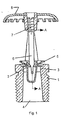
- automatic fire sprinklers (nozzles) of this invention have a frame 1 with an outlet 2 at one end, an orifice 3 which is usually just upstream of the outlet 2, and an inlet 4 which is connectable to a source of fire retarding fluid under pressure.
- the outlet 2 is secured in the normally closed or sealed position by a cap 5, the cap 5 being held in place by a thermally responsive element 6 which is secured in position by bulb assembly screw 7 and releasable when its temperature is increased from a normal ambient condition to a value within a prescribed operating range, by the heat from a fire.
- a stream of fire retarding fluid rushes from the outlet towards a deflector 8, which is connected to the frame 1 at the opposite end from the outlet 2, and is distributed over the area to be protected by the sprinkler (nozzle) from fire.
- the thermally responsive element 6 of this invention is comprised of a frangible glass bulb being itself comprises of a shell 9 and a liquid 10 which, in the room temperature state, nearly completely fills the interior space 11 of the shell 9, except for a relatively small gas pocket 12.
- the shell 9 of the frangible glass bulb of this invention consists of a central region R 1 which has a uniform outer diameter D 1 , a spherical end region R 2 , and a stem end region R 3 , the spherical end region having a seat of diameter D 2 and the stem end region having a seat of diameter D 3 , the distance between the spherical end seat and the stem end seat being length L.
- the frangible glass bulb 6 is of the quick response type with a diameter D 1 of from about 2mm to about 3mm, a diameter D 2 of up to about 2.5mm, a diameter D 3 of up to about 2.2mm, and a length L of from about 12mm to about 24mm, the diameters D 2 and D 3 being in proportion to diameter D 1 .
- the liquid 9 which nearly completely fills the shell 8 of the frangible glass bulb 6 is 1,3-dichlorobenzene.
- frangible glass bulb described above has been found to have the combination of thermophysical properties needed to meet all known prescribed operating temperature range, functionality, and maximum RTI requirements for automatic fire sprinklers, as well as, provide a boiling point well above that necessary to fill at least up to 141°C nominal operating temperature rating frangible glass bulbs, in addition to, providing a desirable reduction in Health Hazard and Contact Hazard Ratings.
Landscapes
- Health & Medical Sciences (AREA)
- Public Health (AREA)
- Business, Economics & Management (AREA)
- Emergency Management (AREA)
- Fire-Extinguishing By Fire Departments, And Fire-Extinguishing Equipment And Control Thereof (AREA)
- Catching Or Destruction (AREA)
Description
- THIS INVENTION relates to a thermally responsive frangible bulb of the type used to automatically release quick response, fire protection sprinklers (nozzles) or, other types of thermally actuated devices.
- Automatic fire sprinklers (nozzles) have a frame with an outlet at one end, an orifice which is usually just upstream of the outlet, and an inlet which is connectable to a source of fire retarding fluid under pressure. The outlet is secured in the normally closed or sealed position by a cap, the cap being held in place by a thermally responsive element which is releasable when its temperature is increased from a normal ambient condition to a value within a prescribed operating range, by the heat from a fire. Upon release of the thermally responsive element, a stream of fire retarding fluid rushes from the outlet towards a deflector, which is mounted on the frame at the opposite end from the outlet, and is distributed over the area to be protected by the sprinkler (nozzle) from fire.
- The two primary types of thermally responsive elements used to automatically release fire sprinklers are fusible solder links and frangible glass bulbs. Automatic fire sprinklers were first commercially introduced in the 1870's with various types of fusible solder links. Although ultimately satisfactory, a great deal of effort went into the development of the fusible solder links to ensure, among other requirements, that they would: not creep apart, over time, at the normally expected ambient temperature conditions; not be deteriorated or corroded by the normally expected environmental conditions; release with a sharp, positive action; be thrown free of the sprinkler upon activation, so as to not interfere with the distribution of the fire retarding fluid; and, respond promptly to fire conditions.
- The search for improvements to fusible solder links, which would achieve these requirements, ultimately led to the invention of frangible glass bulb elements, for use in automatic fire sprinklers, as exemplified and discussed in U.S. Patent 654188, U.S. Patent 842725 and U.S. Patent 1639911. With general improvements in material, glass forming, as well as metal casting technology, it has been possible, within the last 20 years or so, to reduce the size of the frangible glass elements and the frames of automatic fire sprinklers, as initially typified by U.S. Patent 4121665 and U.S. Patent 4167974. However, the principles concerning the method of operation of frangible glass bulbs as well as the advantages of their use, in automatic fire sprinkler applications, have remained essentially the same. The inherent nature of frangible glass bulb elements not only addressed the above mentioned performance requirements for fusible solder links, and indeed for automatic fire sprinklers in general, at a low manufacturing cost for the thermally responsive element, they have also ultimately provided a ready means for automating the assembly of automatic fire sprinklers.
- The successful use of frangible glass bulbs, as thermally responsive elements for automatic fire sprinklers, has comprised; particular strength, thermophysical, shape and dimensional requirements for the glass shell which forms the exterior of the bulbs; the need to have certain thermophysical properties for the liquid used to fill the glass shell; and the necessity for precise control over the extent to which the glass shell is filled with liquid prior to sealing. Some discussion of the required combinations of attributes are presented in U.S. Patents 1290602, 1290762 and Re. 16132. Although it has been found that sodium borosilicate glass is more preferable to quartz material for use in forming the shell of the bulbs, and other liquids have been found to be more preferable to the carbon tetrachloride initially used for filling the bulbs, the basic description of the operating cycle of frangible glass bulbs has remained substantially the same, as stated in the Third Edition of the Grinnell Company Inc. pamphlet Grinnell Quarts Bulb Sprinkler dated May 1929, that is -
- "The bulb is initially filled with a liquid, the remaining space being largely a bubble. The liquid used has been chosen because of its low freezing point, large co-efficient of (thermal) expansion, slight compressibility, low specific heat and the reluctance with which it retains air in solution. When the head (fire sprinkler) is exposed to rising temperature, the liquid expands and gradually the bubble decreases in size, the air being forced into solution because of the increasing pressure and in spite of the elevated temperature. Finally, all of the air becomes dissolved and the entire bulb is filled with the expanding liquid. When this occurs, an almost irresistible internal force is brought to bear on the walls of the bulb and fracture soon occurs. At the instant of rupture the pressure is suddenly decreased so that the air which has been held in solution is free to escape with a mildly explosive action which is sufficient to completely shatter the bulb even in spite of heavy loadings (due to the sprinkler assembly)."
- In the publication "Sprechsaal", Volume 121, No. 9, 1988, criteria for selecting liquids for use in frangible bulbs for sprinklers are discussed in a paper entitled "Untersuchung der Einflußgrößen beim Bersten von Sprinklerampullen". Characteristics of a wide range of substances are set out in a list on page 786. The list in effect does no more than present values for pressure gradients of various liquids derived by calculation from published data, and a limited number of such values derived experimentally. The conclusion is reached that "only glycerine, ethylene glycol and polyethylene glycol can be considered" because of problems encountered with working with aniline, bromoform and di-iodine methane.
- Starting in the early 1970's, research into the requirements for making further improvements in the safety to life benefits provided by automatic fire sprinkler systems demonstrated that safety to life could be substantially enhanced through the use of so-called "quick response" or "fast response" thermally responsive elements for the automatic fire sprinklers. Further research in the 1980's showed that property protection could also be enhanced by the use of the quick response elements. Up until the mid to late 1980's, fusible solder links had an advantage over frangible glass bulbs in that they could readily achieve the desired thermal sensitivity for quick response sprinklers through utilising links constructed of thin wall, high thermal conductivity metals joined by a thin bond of fusible solder. However, improvements in glass bulb formation machinery along with inventions concerning alternate formations for the shell of frangible glass bulbs, as described in U.S. Patent 4796710 and U.S. Patent 4993496 have provided the means for achieving the structural attributes needed for them to be able to provide quick response operating characteristics. In addition, when combined with the use of more thermophysically responsive liquids, frangible glass bulbs have been able to be produced with the thermal sensitivity requirements for quick response sprinklers, as described below.
- Since the invention of the frangible glass bulb sprinkler, various types of liquids have been used for filling the bulbs, such as: mercury, carbon tectrachloride, alcohol, tetrachloroethane, acetone, amyl acetate, triethylene glycol, glycol diacetate, ethylene glycol, glycerol, and other dielectric fluids commonly used for heat transfer applications. However, these types of fluids do not offer the combination of properties needed to achieve quick response operating characteristics as well as low Hazard Ratings in cost effective frangible glass bulbs having a nominal operating temperature rating of at least up to 93°C and, preferably at least up to 141°C.
- Initially, trichloromethane was used for the filling of quick response, frangible glass bulbs, but more recently liquids such as tetrachloroethylene (perchloroethylene) as described in U.S. Patent 4938294 have been used to fill bulbs having a nominal operating temperature rating of up to 93°C. Because the boiling point of the tetrachloroethylene liquid is about 121°C, it is not generally suitable for use in filling the subsequently developed quick response, frangible glass bulbs having a nominal operating temperature rating of up to 93°C. Because of the boiling point of the tetrachloroethylene liquid is about 121°C, it is not generally suitable for use in filling the subsequently developed quick response, frangible glass bulbs having a nominal operating temperature rating of 141°C and other liquids have been used exclusively for filling high temperature bulbs.
- It is an object of the invention to provide an improved thermally responsive frangible bulb.
- According to the invention, there is provided a thermally responsive frangible bulb comprising a shell defining a closed interior space containing a liquid which expands to fill the space and fracture the bulb when heated to within a pre-determined temperature range, wherein the liquid comprises at least one member from either of the chemical groups consisting of derivatives of aromatic hydrocarbons containing two or more halogen substituents and aliphatic amides.
- Although the technical choice of suitable liquids for fast response sprinkler bulbs has been based on consideration of thermophysical properties such as compressibility, thermal expansivity and thermal conductivity, for example as described in U.S. patent 4938294, the data available for candidate liquids is sparse, often dubious and rarely in the pressure/temperature regime of a sprinkler bulb at operation. It is not possible to accurately predict performance as a bulb filling liquid based on incomplete or contentious literature values. Practically no independent empirical measures exist of important liquid properties such as the dP/dT ratio which defines the relationship between bulb operating temperature and sensitivity. The choice of the most suitable liquid depends on an extensive empirical testing programme where the thermophysical factors outlined above will indicate, but not exclude candidate substances. Examples of liquids assessed by this approach are shown in Table 1. In addition, consideration should be made of factors such as melting and boiling points, long term stability, flammability, toxicity and cost and availability of liquids.
Thermophysical Properties of Expanding Liquids Substance Boiling Point (°C) Density (g/cm) Heat Capacity (J/°K/cm3) Thermal Conductivity (W/m/°K) Thermal Expansion (cm/°K) dP/dT (measured) (Bar/°K) 1,2 Dibromobenzene 224 1.956 1.54 12.51 1,3 Dichlorobenzene 173 1.28 1.4 0.13 0.00094 11.20 1,3 Dioxolane 74 1.06 13.11 1 Bromo 3 Chlorobenzene196 1.63 1.47 11.79 Cyclohexane 81 0.779 1.4 012 0.0018 9.17 Formamide 210 1.134 15.22 N,N Dimethylformamide 153 0.944 1.9 0.00104 13.82 Propanone (Acetone) 56 0.791 1.69 0.16 0.00149 Tetrachloroethylene 121 1.61 1.38 0.11 0.00102 11.22 - By means of detailed experimental analysis the desirable properties for performance can be correlated with the chemical structure in terms of specific combinations of functional groups, and identification of a suitable liquid can be narrowed down to members of chemical structure classes. A preferred filling liquid comprises a member of the group of halogenated aromatic hydrocarbons containing two or more halogen substituents, or of the group of aliphatic amides.
- Preferably, the halogenated aromatic hydrocarbon is benzene for which two or more hydrogens are substituted by a halogen, such as 1,3 dibromobenzene illustrated below.

- The above is an example of a Hückel aromatic hydrocarbon, containing 2n+2π electrons, with two halogen groups bound directly to the aromatic ring. The halogen may be selected from bromine, chlorine or fluorine, for example, 1,2-dichlorobenzene, 1,3-dichlorobenzene, 1,2-dibromobenzene, 1-bromo-2-chlorobenzene, 1-bromo-2-fluorobenzene, 1-bromo-4-fluorobenzene, 1-chloro-2-fluorobenzene, 1-chloro-4-fluorobenzen, 1,2,4-dichlorobenzene, 1-bromo-2,4,5-trifluorobenzene, 1,3-dichloro-2,5-difluorobenzene or a mixture of any two or more of the above halogen derivatives.
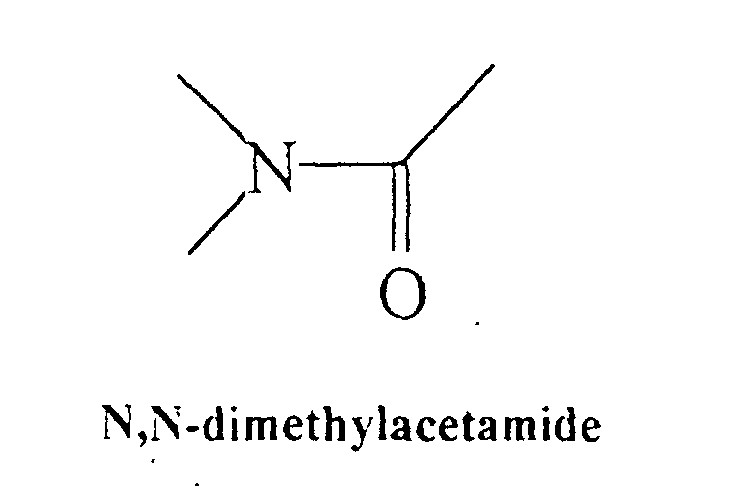
- Compounds containing the amide group such as formamide, N,N dimethylformamide, N,N-dimethylacetamide and N-methylformamide possess relevant functionality for use in liquids for trigger elements N,N-dimethylacetamide is illustrated below and is an example of the aliphatic amide group, containing the amide linkage (-C(O)N-).
- In combination with satisfying sensitivity requirements to fast response standard, the present invention bestows a number of advantageous properties. These include benefits to the manufacturer of low scrap wastage due to high values of dP/dT ratio, greater predictability of properties and performance across an extended range of temperature ratings and more efficient manufacturing processes and hazard analysis for manufacturers and end users and use in sub-zero environments where temperatures approach -50°C or less for extended periods. The liquids contained in the glass bulbs are readily available and represent a reduced level of toxicity in comparison with previously used substances, some of which, such as carbon tetrachloride and trichloroethane, have at this date been banned for many applications.
- An embodiment of the invention will now be described, by way of example, with reference to the accompanying drawings, in which:-
- Fig. 1 is a partial sectional view of an automatic fire sprinkler showing a preferred embodiment of the quick response, frangible glass bulb, thermally responsive element of this invention;
- and Fig. 2 is an enlarged, axial, cross-sectional view of the quick response, frangible glass bulb of this invention taken along the line A-A of Fig. 1.
-
- With reference to Fig. 1, automatic fire sprinklers (nozzles) of this invention have a
frame 1 with anoutlet 2 at one end, anorifice 3 which is usually just upstream of theoutlet 2, and aninlet 4 which is connectable to a source of fire retarding fluid under pressure. Theoutlet 2 is secured in the normally closed or sealed position by acap 5, thecap 5 being held in place by a thermallyresponsive element 6 which is secured in position bybulb assembly screw 7 and releasable when its temperature is increased from a normal ambient condition to a value within a prescribed operating range, by the heat from a fire. Upon release of the thermallyresponsive element 6, a stream of fire retarding fluid rushes from the outlet towards a deflector 8, which is connected to theframe 1 at the opposite end from theoutlet 2, and is distributed over the area to be protected by the sprinkler (nozzle) from fire. - With reference to Figs. 1 and 2, the thermally
responsive element 6 of this invention is comprised of a frangible glass bulb being itself comprises of ashell 9 and aliquid 10 which, in the room temperature state, nearly completely fills theinterior space 11 of theshell 9, except for a relativelysmall gas pocket 12. With further reference to Fig. 2, theshell 9 of the frangible glass bulb of this invention consists of a central region R1 which has a uniform outer diameter D1, a spherical end region R2, and a stem end region R3, the spherical end region having a seat of diameter D2 and the stem end region having a seat of diameter D3, the distance between the spherical end seat and the stem end seat being length L. - In the preferred embodiment of this invention, the
frangible glass bulb 6 is of the quick response type with a diameter D1 of from about 2mm to about 3mm, a diameter D2 of up to about 2.5mm, a diameter D3 of up to about 2.2mm, and a length L of from about 12mm to about 24mm, the diameters D2 and D3 being in proportion to diameter D1. Theliquid 9 which nearly completely fills the shell 8 of thefrangible glass bulb 6 is 1,3-dichlorobenzene. - The frangible glass bulb described above has been found to have the combination of thermophysical properties needed to meet all known prescribed operating temperature range, functionality, and maximum RTI requirements for automatic fire sprinklers, as well as, provide a boiling point well above that necessary to fill at least up to 141°C nominal operating temperature rating frangible glass bulbs, in addition to, providing a desirable reduction in Health Hazard and Contact Hazard Ratings.
Claims (7)
- A thermally responsive frangible bulb comprising a shell defining a closed interior space containing a liquid which expands to fill the space and fracture the bulb when heated to within a predetermined temperature range, wherein the liquid is selected from the group comprising at least one halogen derivative of an aromatic hydrocarbon containing two or more halogen substituents, an aliphatic amide, and a mixture thereof.
- A frangible bulb according to Claim 1, wherein the liquid is benzene in which two hydrogens are substituted with halogens, for example 1,3-dichlorobenzene.
- A frangible bulb according to Claim 1, wherein the liquid is benzene in which three hydrogens are substituted with halogens, for example 1,2,4-dichlorobenzene.
- A frangible bulb according to Claim 1, wherein the liquid is benzene in which four hydrogens are substituted with halogens, for example 1 -bromo-2,4,5-trifluorobenzene.
- A frangible bulb according to Claim 1, wherein the liquid is an aliphatic amide, for example N,N-dimethylformamide, N,N-dimethylacetamide, N-methylformamide formamide.
- A frangible bulb according to Claim 1, wherein the liquid is a mixture of any two or more of the compounds according to Claims 2 to 5.
- An automatic fire sprinkler having an inlet which in use is connected to a source of fire retarding fluid under pressure, and an outlet which is secured in a normally closed or sealed condition by a thermally responsive frangible bulb according to any one of the preceding claims.
Applications Claiming Priority (2)
| Application Number | Priority Date | Filing Date | Title |
|---|---|---|---|
| GB9620598 | 1996-10-03 | ||
| GBGB9620598.4A GB9620598D0 (en) | 1996-10-03 | 1996-10-03 | Thermally responsive frangible bulb |
Publications (3)
| Publication Number | Publication Date |
|---|---|
| EP0838242A2 EP0838242A2 (en) | 1998-04-29 |
| EP0838242A3 EP0838242A3 (en) | 1999-08-04 |
| EP0838242B1 true EP0838242B1 (en) | 2002-06-05 |
Family
ID=10800862
Family Applications (1)
| Application Number | Title | Priority Date | Filing Date |
|---|---|---|---|
| EP97307891A Expired - Lifetime EP0838242B1 (en) | 1996-10-03 | 1997-10-02 | Thermally responsive frangible bulb |
Country Status (4)
| Country | Link |
|---|---|
| US (1) | US5967238A (en) |
| EP (1) | EP0838242B1 (en) |
| DE (1) | DE69713023D1 (en) |
| GB (1) | GB9620598D0 (en) |
Cited By (4)
| Publication number | Priority date | Publication date | Assignee | Title |
|---|---|---|---|---|
| EP2258451A1 (en) | 2009-06-05 | 2010-12-08 | Job Lizenz GmbH & Co. KG | Thermal release element for sprinklers, valves or similar |
| DE202011050661U1 (en) | 2011-07-07 | 2011-09-09 | Job Lizenz Gmbh & Co. Kg | Thermal release element for sprinklers, valves or the like |
| DE202012100623U1 (en) * | 2012-02-24 | 2012-03-22 | Job Lizenz Gmbh & Co. Kg | Fire protection device for small electrical appliances |
| DE102011009099A1 (en) * | 2011-01-21 | 2012-07-26 | Kostal Industrie Elektrik Gmbh | Over-temperature protection device for e.g. fire-extinguishing system, has tensioned spring that is provided on conductive casing for clamping sprinkler bulb capsule axially so that intact holding of capsule is possible |
Families Citing this family (15)
| Publication number | Priority date | Publication date | Assignee | Title |
|---|---|---|---|---|
| US5829532A (en) | 1997-03-07 | 1998-11-03 | Central Sprinkler Corporation | Low pressure, early suppression fast response sprinklers |
| US6557865B1 (en) | 1998-10-09 | 2003-05-06 | The Burton Corporation | Highback with adjustable stiffness |
| DE202010013607U1 (en) * | 2010-09-27 | 2011-12-28 | Job Lizenz Gmbh & Co. Kg | Thermal release element for a thermally controlled switching element |
| US8800588B2 (en) * | 2011-12-13 | 2014-08-12 | GM Global Technology Operations LLC | Glass bulb thermally-activated pressure relief device, safety inspection method, and equipment |
| US9265981B2 (en) * | 2012-12-12 | 2016-02-23 | The Viking Corporation | Pip cap assembly for a fire protection sprinkler |
| US9573007B2 (en) | 2013-03-15 | 2017-02-21 | Tyco Fire Products Lp | Fire protection sprinkler |
| CN106999746B (en) | 2014-11-27 | 2020-10-23 | 马里奥夫有限公司 | Automatic-unfolding fire-extinguishing spray head |
| RU2652587C2 (en) * | 2015-11-18 | 2018-04-26 | Общество С Ограниченной Ответственностью "Форносовский Литейно-Механический Завод" | Sprinkler with control over operation |
| US20170319885A1 (en) * | 2016-05-06 | 2017-11-09 | Bulb Link, LLC | Heat-Sensitive Trigger for a Fire Sprinkler Valve |
| US9539451B1 (en) | 2016-05-06 | 2017-01-10 | Bulb Link, LLC | Heat-sensitive trigger for a fire sprinkler valve |
| CN106730543A (en) * | 2017-03-10 | 2017-05-31 | 上海元驰商贸有限公司 | Seal receptacle and shower nozzle |
| US11094487B2 (en) * | 2018-06-25 | 2021-08-17 | 24M Technologies, Inc. | Current interrupt device based on thermal activation of frangible glass bulb |
| EP3753607B1 (en) * | 2019-06-17 | 2025-02-26 | Marioff Corporation OY | Sprinkler bulb |
| CN220237646U (en) * | 2020-08-19 | 2023-12-26 | 米尼麦克斯维京研发有限公司 | Automatic fire protection sprinkler assembly |
| ES2984542T3 (en) * | 2020-12-04 | 2024-10-29 | Marioff Corp Oy | Sprinkler bulb |
Family Cites Families (17)
| Publication number | Priority date | Publication date | Assignee | Title |
|---|---|---|---|---|
| USRE16132E (en) | 1925-08-04 | Automatic sprinkler | ||
| US1639911A (en) | 1926-03-12 | 1927-08-23 | Mather & Platt Ltd | Automatic sprinkler or fire extinguisher |
| US4121665A (en) | 1975-03-20 | 1978-10-24 | Standard Fire Protection Equipment Co. | Automatic sprinkler head |
| DE2639245C2 (en) | 1976-09-01 | 1982-04-08 | Eduard J. Ing.(grad.) 2070 Ahrensberg Job | Fire extinguisher head for automatic fire extinguishing systems |
| JPS5988166A (en) * | 1982-11-10 | 1984-05-22 | ダイキン工業株式会社 | Fire extinguishing agent |
| US4536298A (en) * | 1983-03-30 | 1985-08-20 | Dainippon Ink And Chemicals, Inc. | Aqueous foam fire extinguisher |
| JPS6266876A (en) * | 1985-09-09 | 1987-03-26 | エドウアルド ヨツト・ イヨプ | Glass valve for water sprinkler head |
| CH672745A5 (en) * | 1987-02-13 | 1989-12-29 | Johann Georg Mohler | |
| US4898246A (en) | 1987-07-06 | 1990-02-06 | Total Walther Feuerschutz Gmbh | Quick release valve for sprinkler head |
| DE3819749A1 (en) * | 1988-06-10 | 1989-12-14 | Verband Der Sachversicherer Ev | THERMAL RELEASE DEVICE FOR SPRINKLERS FOR FIXED FIRE EXTINGUISHING SYSTEMS |
| US5254354A (en) * | 1990-12-07 | 1993-10-19 | Landec Corporation | Food package comprised of polymer with thermally responsive permeability |
| KR930003391B1 (en) * | 1989-11-17 | 1993-04-26 | 한국과학기술연구원 | Liquid extinguishing agent composition |
| EP0508832B1 (en) * | 1991-04-11 | 1996-08-14 | Brissco Equipment Limited | Methods and apparatus for temperature sensing |
| SG97741A1 (en) * | 1993-11-01 | 2003-08-20 | Robert E Tyler | Fire fighting and cooling foam composition |
| US5392993A (en) * | 1994-01-21 | 1995-02-28 | Grinnell Corporation, | Fire protection nozzle |
| US5932285A (en) * | 1995-02-17 | 1999-08-03 | Medlogic Global Corporation | Encapsulated materials |
| WO1997026945A1 (en) * | 1996-01-25 | 1997-07-31 | Norbulb Sprinkler Elemente Gmbh | Sprinkler actuator |
-
1996
- 1996-10-03 GB GBGB9620598.4A patent/GB9620598D0/en active Pending
-
1997
- 1997-10-02 DE DE69713023T patent/DE69713023D1/en not_active Expired - Lifetime
- 1997-10-02 EP EP97307891A patent/EP0838242B1/en not_active Expired - Lifetime
- 1997-10-02 US US08/942,864 patent/US5967238A/en not_active Expired - Lifetime
Cited By (9)
| Publication number | Priority date | Publication date | Assignee | Title |
|---|---|---|---|---|
| EP2258451A1 (en) | 2009-06-05 | 2010-12-08 | Job Lizenz GmbH & Co. KG | Thermal release element for sprinklers, valves or similar |
| DE102011009099A1 (en) * | 2011-01-21 | 2012-07-26 | Kostal Industrie Elektrik Gmbh | Over-temperature protection device for e.g. fire-extinguishing system, has tensioned spring that is provided on conductive casing for clamping sprinkler bulb capsule axially so that intact holding of capsule is possible |
| DE102011009099B4 (en) | 2011-01-21 | 2022-02-17 | Kostal Industrie Elektrik Gmbh | Overtemperature protection for an electrical system and electrical systems with an overtemperature protection |
| DE202011050661U1 (en) | 2011-07-07 | 2011-09-09 | Job Lizenz Gmbh & Co. Kg | Thermal release element for sprinklers, valves or the like |
| EP2543416A2 (en) | 2011-07-07 | 2013-01-09 | Job Lizenz GmbH & Co. KG | Thermal release element for sprinklers, valves or similar |
| EP2543416A3 (en) * | 2011-07-07 | 2014-04-09 | Job Lizenz GmbH & Co. KG | Thermal release element for sprinklers, valves or similar |
| DE202012100623U1 (en) * | 2012-02-24 | 2012-03-22 | Job Lizenz Gmbh & Co. Kg | Fire protection device for small electrical appliances |
| EP2630994B1 (en) * | 2012-02-24 | 2018-05-30 | Job Lizenz GmbH & Co. KG | Small electrical device with a fire protection device |
| EP3360605A1 (en) * | 2012-02-24 | 2018-08-15 | Job Lizenz GmbH & Co. KG | Fire protection device for small electric devices |
Also Published As
| Publication number | Publication date |
|---|---|
| GB9620598D0 (en) | 1996-11-20 |
| US5967238A (en) | 1999-10-19 |
| DE69713023D1 (en) | 2002-07-11 |
| EP0838242A3 (en) | 1999-08-04 |
| EP0838242A2 (en) | 1998-04-29 |
Similar Documents
| Publication | Publication Date | Title |
|---|---|---|
| EP0838242B1 (en) | Thermally responsive frangible bulb | |
| RU2097082C1 (en) | Fire-fighting plant | |
| US6161624A (en) | Linear fire extinguisher | |
| US6918545B2 (en) | Sprinkler head trigger assembly | |
| JP6732191B2 (en) | Device for warning of pre-fire conditions resulting from local overheating of electrical equipment | |
| KR101274406B1 (en) | Aerosol Extinguisher Having Duplicative Ignition Unit and Ignition Unit Therefor | |
| EP0129568A1 (en) | A sprinkler unit | |
| KR102580130B1 (en) | Fire-extinguishing implement for small space | |
| CA3015905C (en) | Single-action emergency thermal valve | |
| KR20130045503A (en) | Fire extinguishing device for fire fighting | |
| KR20120134353A (en) | Smart head automatic operating means for extinguisher | |
| KR20130118723A (en) | Low-lead residential fire protection sprinklers | |
| US4938294A (en) | Trigger element for a sprinkler | |
| EP0508832B1 (en) | Methods and apparatus for temperature sensing | |
| CN101065604B (en) | Alloys for fusible plugs and fusible plugs | |
| US2796494A (en) | Fire fuse link | |
| US3277860A (en) | Sensor for heat or temperature detection and fire detection | |
| US5503231A (en) | Chimney fire safety system | |
| US3390365A (en) | Sensor for heat or temperature detection and fire detection | |
| AU2016354580B2 (en) | Dry sprinkler | |
| JP4032094B2 (en) | Soluble stopper alloy and fusible stopper | |
| CN113257624A (en) | Temperature control switch capable of releasing glass bubbles at temperature and using method thereof | |
| RU2619729C1 (en) | Method of fire extinguisher activation (versions) and device for its realisation (versions) | |
| CN223988076U (en) | Automatic repeating fire extinguisher | |
| US9494476B2 (en) | Indicator device for an enclosure with sealing compound |
Legal Events
| Date | Code | Title | Description |
|---|---|---|---|
| PUAI | Public reference made under article 153(3) epc to a published international application that has entered the european phase |
Free format text: ORIGINAL CODE: 0009012 |
|
| AK | Designated contracting states |
Kind code of ref document: A2 Designated state(s): AT BE CH DE DK LI |
|
| PUAL | Search report despatched |
Free format text: ORIGINAL CODE: 0009013 |
|
| AK | Designated contracting states |
Kind code of ref document: A3 Designated state(s): AT BE CH DE DK ES FI FR GB GR IE IT LI LU MC NL PT SE |
|
| 17P | Request for examination filed |
Effective date: 20000204 |
|
| AKX | Designation fees paid |
Free format text: AT BE CH DE DK LI |
|
| RBV | Designated contracting states (corrected) |
Designated state(s): DE DK ES GB SE |
|
| RAP1 | Party data changed (applicant data changed or rights of an application transferred) |
Owner name: TYCO FIRE PRODUCTS MANUFACTURING LIMITED |
|
| GRAG | Despatch of communication of intention to grant |
Free format text: ORIGINAL CODE: EPIDOS AGRA |
|
| 17Q | First examination report despatched |
Effective date: 20010816 |
|
| GRAG | Despatch of communication of intention to grant |
Free format text: ORIGINAL CODE: EPIDOS AGRA |
|
| GRAH | Despatch of communication of intention to grant a patent |
Free format text: ORIGINAL CODE: EPIDOS IGRA |
|
| GRAH | Despatch of communication of intention to grant a patent |
Free format text: ORIGINAL CODE: EPIDOS IGRA |
|
| GRAA | (expected) grant |
Free format text: ORIGINAL CODE: 0009210 |
|
| AK | Designated contracting states |
Kind code of ref document: B1 Designated state(s): DE DK ES GB SE |
|
| REG | Reference to a national code |
Ref country code: GB Ref legal event code: FG4D |
|
| REF | Corresponds to: |
Ref document number: 69713023 Country of ref document: DE Date of ref document: 20020711 |
|
| PG25 | Lapsed in a contracting state [announced via postgrant information from national office to epo] |
Ref country code: SE Free format text: LAPSE BECAUSE OF FAILURE TO SUBMIT A TRANSLATION OF THE DESCRIPTION OR TO PAY THE FEE WITHIN THE PRESCRIBED TIME-LIMIT Effective date: 20020905 Ref country code: DK Free format text: LAPSE BECAUSE OF FAILURE TO SUBMIT A TRANSLATION OF THE DESCRIPTION OR TO PAY THE FEE WITHIN THE PRESCRIBED TIME-LIMIT Effective date: 20020905 |
|
| PG25 | Lapsed in a contracting state [announced via postgrant information from national office to epo] |
Ref country code: DE Free format text: LAPSE BECAUSE OF FAILURE TO SUBMIT A TRANSLATION OF THE DESCRIPTION OR TO PAY THE FEE WITHIN THE PRESCRIBED TIME-LIMIT Effective date: 20020906 |
|
| PG25 | Lapsed in a contracting state [announced via postgrant information from national office to epo] |
Ref country code: ES Free format text: LAPSE BECAUSE OF FAILURE TO SUBMIT A TRANSLATION OF THE DESCRIPTION OR TO PAY THE FEE WITHIN THE PRESCRIBED TIME-LIMIT Effective date: 20021220 |
|
| PLBE | No opposition filed within time limit |
Free format text: ORIGINAL CODE: 0009261 |
|
| STAA | Information on the status of an ep patent application or granted ep patent |
Free format text: STATUS: NO OPPOSITION FILED WITHIN TIME LIMIT |
|
| 26N | No opposition filed |
Effective date: 20030306 |
|
| PGFP | Annual fee paid to national office [announced via postgrant information from national office to epo] |
Ref country code: GB Payment date: 20151027 Year of fee payment: 19 |
|
| GBPC | Gb: european patent ceased through non-payment of renewal fee |
Effective date: 20161002 |
|
| PG25 | Lapsed in a contracting state [announced via postgrant information from national office to epo] |
Ref country code: GB Free format text: LAPSE BECAUSE OF NON-PAYMENT OF DUE FEES Effective date: 20161002 |