EP0838640A2 - Système d'équilibrage du niveau d'huile pour plusieurs compresseurs - Google Patents
Système d'équilibrage du niveau d'huile pour plusieurs compresseurs Download PDFInfo
- Publication number
- EP0838640A2 EP0838640A2 EP97112592A EP97112592A EP0838640A2 EP 0838640 A2 EP0838640 A2 EP 0838640A2 EP 97112592 A EP97112592 A EP 97112592A EP 97112592 A EP97112592 A EP 97112592A EP 0838640 A2 EP0838640 A2 EP 0838640A2
- Authority
- EP
- European Patent Office
- Prior art keywords
- oil level
- oil
- compressors
- line
- way valve
- Prior art date
- Legal status (The legal status is an assumption and is not a legal conclusion. Google has not performed a legal analysis and makes no representation as to the accuracy of the status listed.)
- Ceased
Links
- 239000003507 refrigerant Substances 0.000 claims abstract description 124
- 238000004891 communication Methods 0.000 claims abstract description 81
- 238000011144 upstream manufacturing Methods 0.000 claims abstract description 30
- 238000004378 air conditioning Methods 0.000 claims abstract description 29
- 239000007788 liquid Substances 0.000 claims abstract description 15
- 238000001816 cooling Methods 0.000 claims description 59
- 238000010438 heat treatment Methods 0.000 claims description 59
- 239000003921 oil Substances 0.000 description 674
- 238000000034 method Methods 0.000 description 44
- 230000007423 decrease Effects 0.000 description 24
- 230000001105 regulatory effect Effects 0.000 description 18
- 238000010276 construction Methods 0.000 description 15
- 230000001276 controlling effect Effects 0.000 description 13
- 230000006835 compression Effects 0.000 description 11
- 238000007906 compression Methods 0.000 description 11
- 238000010586 diagram Methods 0.000 description 10
- 230000003111 delayed effect Effects 0.000 description 8
- 239000003595 mist Substances 0.000 description 2
- 238000012986 modification Methods 0.000 description 2
- 230000004048 modification Effects 0.000 description 2
- 238000005187 foaming Methods 0.000 description 1
Images


Classifications
-
- F—MECHANICAL ENGINEERING; LIGHTING; HEATING; WEAPONS; BLASTING
- F25—REFRIGERATION OR COOLING; COMBINED HEATING AND REFRIGERATION SYSTEMS; HEAT PUMP SYSTEMS; MANUFACTURE OR STORAGE OF ICE; LIQUEFACTION SOLIDIFICATION OF GASES
- F25B—REFRIGERATION MACHINES, PLANTS OR SYSTEMS; COMBINED HEATING AND REFRIGERATION SYSTEMS; HEAT PUMP SYSTEMS
- F25B31/00—Compressor arrangements
- F25B31/002—Lubrication
-
- F—MECHANICAL ENGINEERING; LIGHTING; HEATING; WEAPONS; BLASTING
- F04—POSITIVE - DISPLACEMENT MACHINES FOR LIQUIDS; PUMPS FOR LIQUIDS OR ELASTIC FLUIDS
- F04B—POSITIVE-DISPLACEMENT MACHINES FOR LIQUIDS; PUMPS
- F04B49/00—Control, e.g. of pump delivery, or pump pressure of, or safety measures for, machines, pumps, or pumping installations, not otherwise provided for, or of interest apart from, groups F04B1/00 - F04B47/00
-
- F—MECHANICAL ENGINEERING; LIGHTING; HEATING; WEAPONS; BLASTING
- F04—POSITIVE - DISPLACEMENT MACHINES FOR LIQUIDS; PUMPS FOR LIQUIDS OR ELASTIC FLUIDS
- F04B—POSITIVE-DISPLACEMENT MACHINES FOR LIQUIDS; PUMPS
- F04B39/00—Component parts, details, or accessories, of pumps or pumping systems specially adapted for elastic fluids, not otherwise provided for in, or of interest apart from, groups F04B25/00 - F04B37/00
- F04B39/02—Lubrication
- F04B39/0207—Lubrication with lubrication control systems
-
- F—MECHANICAL ENGINEERING; LIGHTING; HEATING; WEAPONS; BLASTING
- F16—ENGINEERING ELEMENTS AND UNITS; GENERAL MEASURES FOR PRODUCING AND MAINTAINING EFFECTIVE FUNCTIONING OF MACHINES OR INSTALLATIONS; THERMAL INSULATION IN GENERAL
- F16N—LUBRICATING
- F16N19/00—Lubricant containers for use in lubricators or lubrication systems
- F16N19/006—Maintaining oil level
-
- F—MECHANICAL ENGINEERING; LIGHTING; HEATING; WEAPONS; BLASTING
- F25—REFRIGERATION OR COOLING; COMBINED HEATING AND REFRIGERATION SYSTEMS; HEAT PUMP SYSTEMS; MANUFACTURE OR STORAGE OF ICE; LIQUEFACTION SOLIDIFICATION OF GASES
- F25B—REFRIGERATION MACHINES, PLANTS OR SYSTEMS; COMBINED HEATING AND REFRIGERATION SYSTEMS; HEAT PUMP SYSTEMS
- F25B13/00—Compression machines, plants or systems, with reversible cycle
-
- F—MECHANICAL ENGINEERING; LIGHTING; HEATING; WEAPONS; BLASTING
- F25—REFRIGERATION OR COOLING; COMBINED HEATING AND REFRIGERATION SYSTEMS; HEAT PUMP SYSTEMS; MANUFACTURE OR STORAGE OF ICE; LIQUEFACTION SOLIDIFICATION OF GASES
- F25B—REFRIGERATION MACHINES, PLANTS OR SYSTEMS; COMBINED HEATING AND REFRIGERATION SYSTEMS; HEAT PUMP SYSTEMS
- F25B2313/00—Compression machines, plants or systems with reversible cycle not otherwise provided for
- F25B2313/023—Compression machines, plants or systems with reversible cycle not otherwise provided for using multiple indoor units
-
- F—MECHANICAL ENGINEERING; LIGHTING; HEATING; WEAPONS; BLASTING
- F25—REFRIGERATION OR COOLING; COMBINED HEATING AND REFRIGERATION SYSTEMS; HEAT PUMP SYSTEMS; MANUFACTURE OR STORAGE OF ICE; LIQUEFACTION SOLIDIFICATION OF GASES
- F25B—REFRIGERATION MACHINES, PLANTS OR SYSTEMS; COMBINED HEATING AND REFRIGERATION SYSTEMS; HEAT PUMP SYSTEMS
- F25B2400/00—General features or devices for refrigeration machines, plants or systems, combined heating and refrigeration systems or heat-pump systems, i.e. not limited to a particular subgroup of F25B
- F25B2400/07—Details of compressors or related parts
- F25B2400/075—Details of compressors or related parts with parallel compressors
-
- F—MECHANICAL ENGINEERING; LIGHTING; HEATING; WEAPONS; BLASTING
- F25—REFRIGERATION OR COOLING; COMBINED HEATING AND REFRIGERATION SYSTEMS; HEAT PUMP SYSTEMS; MANUFACTURE OR STORAGE OF ICE; LIQUEFACTION SOLIDIFICATION OF GASES
- F25B—REFRIGERATION MACHINES, PLANTS OR SYSTEMS; COMBINED HEATING AND REFRIGERATION SYSTEMS; HEAT PUMP SYSTEMS
- F25B2700/00—Sensing or detecting of parameters; Sensors therefor
- F25B2700/03—Oil level
Definitions
- the present invention relates to an oil level equalizing system for a plurality of low-pressure shell-type compressors arranged in parallel.
- Japanese Laid-Open Utility Model Publication (unexamined) No. 4-19675 discloses an oil level equalizing system for a plurality of low-pressure shell-type compressors arranged in parallel.
- Fig. 19 depicts a refrigerating cycle of an air-conditioning equipment employing the conventional oil level equalizing system for the plurality of compressors.
- Fig. 20 is a detailed view of a portion denoted by A in Fig. 19.
- an outdoor unit 1 of the air-conditioning equipment comprises a plurality of low-pressure shell-type compressors 2a, 2b, 2c, a four-way valve 3 for switching the flowing direction of a refrigerant in accordance with a cooling operation and a heating operation, an outdoor heat exchanger 4 which serves as a condenser during the cooling operation and as an evaporator during the heating operation, and an outdoor expansion valve 5 which does not reduce the pressure during the cooling operation but serves as a pressure reduction unit during the heating operation.
- An indoor unit 6a, 6b or 6c comprises an indoor expansion valve 7a, 7b or 7c which does not reduce the pressure during the heating operation but serves as a pressure reduction unit during the cooling operation, and an indoor heat exchanger 8a, 8b or 8c which serves as an evaporator during the cooling operation and as a condenser during the heating operation. Further, the outdoor unit 1 is connected with the indoor units 6a, 6b, 6c to thereby constituting a looped refrigerant circuit.
- Reference numeral 9 designates a suction line which communicates with the suction side of the compressors 2a, 2b, 2c, and reference numerals 10a and 10b designate branch portions of the suction line 9.
- the compressors 2a, 2b, 2c are connected at respective positions adjacent to the normal oil level within the shell with an oil level equalizing line 11 via connecting lines 12a, 12b, 12c.
- the oil level within the compressor 2a lowers, so that the pressure at the connecting portion of the connecting line 12a of the compressor 2a lowers below the pressures at the connecting portions of the connecting lines 12b, 12c of the compressors 2b, 2c. Therefore, the oils within the shells of the compressors 2b, 2c transfer into the shell of the compressor 2a through an oil level equalizing line 11 to prevent shortage of the oil quantity within the compressor 2a. In this way, when the respective compressors 2a, 2b, 2c have the same capacities and the pressures within their respective shells are the same, it becomes possible to adequately control the oil quantities within the respective compressors 2a, 2b, 2c.
- the pressure within the shell of the compressor 2a becomes higher than those within the shells of the compressors 2b, 2c, and the pressure at the connecting portion of the connecting line 12a of the compressor 2a becomes higher than those at the connecting portions of the connecting lines 12b, 12c of the compressors 2b, 2c, so that the oil within the shell of the compressor 2a transfers into the shells of the compressors 2b, 2c through the oil level equalizing line 11 to decrease the oil quantity of the compressor 2a.
- the present invention has been developed to overcome the above-described disadvantages.
- a suction line disposed on the upstream side of a suction line branch portion to each compressor is communicated with an oil level equalizing line via a communication line to increase the pressure within the oil level equalizing line higher than the pressure within the shell of each compressor.
- Another objective of the present invention is to provide the oil level equalizing system of the above-described type which is simple in construction and can be made at a low cost.
- the oil level equalizing system comprises: a suction line having a plurality of branch portions branched therefrom; a plurality of compressors each communicating with one of the plurality of branch portions and each having a low-pressure shell; a plurality of connecting lines each having a first end communicating with the shell at a location adjacent to a normal oil level therein; an oil level equalizing line communicating with second ends of the plurality of connecting lines, and a communication line, through which the suction line communicates with the oil level equalizing line at a location upstream of the plurality of branch portions with respect to a direction of flow of a refrigerant, for increasing a pressure within the oil level equalizing line to a value higher than that within the shell of each of the plurality of compressors.
- a gas/liquid separator may be provided in the suction line for separating a gas refrigerant and a liquid refrigerant, said gas/liquid separator having an upper portion in which the gas refrigerant is accommodated and which communicates with the oil level equalizing line through the communication line.
- an oil/gas separator may be provided in the suction line for separating oil from a gas refrigerant and an accumulator arranged in the suction line upstream of the oil/gas separator with respect to the direction of flow of the refrigerant, said oil/gas separator having a portion in which the gas refrigerant is accommodated and which communicates with the oil level equalizing line through the communication line.
- the accumulator has an upper portion in which the gas refrigerant is accommodated and which communicates with the oil level equalizing line through the communication line.
- the oil level equalizing system may further comprise a two-way valve arranged in a midway portion of the communication line for increasing, when opened, a pressure within the oil level equalizing line to said value, and a two-way valve control means for closing the two-way valve for a predetermined period of time when a continuous running time for cooling or heating reaches a predetermined time.
- the oil level equalizing system comprises a two-way valve arranged in a midway portion of the communication line for increasing, when opened, a pressure within the oil level equalizing line to said value, a plurality of pressure differential detecting units each for detecting a pressure differential between a shell upper portion and a shell lower portion of a corresponding one of the plurality of compressors, and a two-way valve control means for closing the two-way valve when the pressure differential detected by at least one of the plurality of pressure differential detecting units becomes smaller than a predetermined lower limit, and for subsequently opening the two-way valve when the pressure differentials detected by all the pressure differential detecting units become equal to or larger than a predetermined reference pressure differential.
- the oil level equalizing system comprises a two-way valve arranged in a midway portion of the communication line for increasing, when opened, a pressure within the oil level equalizing line to said value, a plurality of oil level detecting units each for detecting an oil level in a corresponding one of the plurality of compressors, and a two-way valve control means for closing the two-way valve when the oil level detected by at least one of the plurality of oil level detecting units becomes lower than a predetermined lower limit, and for subsequently opening the two-way valve when the oil levels detected by all the oil level detecting units become equal to or higher than a predetermined reference oil level.
- low-pressure shell-type compressor as employed throughout this application is defined as a compressor having a low-pressure shell.
- Fig. 1 is a diagram of a refrigerating cycle of an air conditioning equipment employing the oil level equalizing system according to the first embodiment of the present invention
- Fig. 2 is a detailed view of a portion denoted by B in Fig. 1.
- an outdoor unit 1 of an air conditioning equipment comprises a plurality of low-pressure shell-type compressors 2a, 2b, 2c, a four-way valve 3 for switching the flowing direction of a refrigerant in accordance with a cooling operation and a heating operation, an outdoor heat exchanger 4 which serves as a condenser during the cooling operation and as an evaporator during the heating operation, and an outdoor expansion valve 5 which does not reduce the pressure during the cooling operation but serves as a pressure reduction unit during the heating operation.
- Each of indoor units 6a, 6b, 6c comprises an indoor expansion valve 7a, 7b or 7c which does not reduce the pressure during the heating operation but serves as a pressure reduction unit during the cooling operation, and an indoor heat exchanger 8a, 8b or 8c which serves as an evaporator during the cooling operation and as a condenser during the heating operation. Further, the outdoor unit 1 is connected to the indoor units 6a, 6b, 6c to thereby constitute a looped refrigerant circuit.
- Reference numeral 9 designates a suction line which communicates with the suction side of the compressors 2a, 2b, 2c, and reference numerals 10a, 10b designate branch portions branched from the suction line 9 and communicating with the compressors 2a, 2b, 2c.
- the compressors 2a, 2b, 2c are connected at respective positions adjacent to the normal oil level within the shell with an oil level equalizing line 11 via oil level equalizing line connecting lines 12a, 12b, 12c (these lines are often referred to simply as the connecting lines hereinafter).
- Reference numeral 13 designates a communication line for communicating the suction line 9 with the oil level equalizing line 11 at a location upstream of the suction line branch portions 10a, 10b for the compressor 2a, 2b, 2c with respect to the direction of flow of a refrigerant.
- the oil level equalizing system comprises the plurality of low-pressure shell-type compressors 2a, 2b, 2c, the connecting lines 12a, 12b, 12c for connecting the oil level equalizing line 11 with the compressors 2a, 2b, 2c at locations adjacent to the normal oil levels within respective shells, and the communication line 13 for communicating the oil level equalizing line 11 with the suction line 9 on the upstream side of the suction line branch portions 10a, 10b for the respective compressors 2a, 2b, 2c to increase the pressure within the oil level equalizing line 11 higher than the pressures within the shells of the respective compressors 2a, 2b, 2c.
- the plurality of compressors 2a, 2b, 2c include compressors having different capacities or variable capacities, and that the compressor 2a has a smaller capacity than those of the compressors 2b, 2c.
- the delivery oil quantity and the return oil quantity in the respective compressors 2a, 2b, 2c will be explained hereinafter.
- the oil quantity supplied to a compression chamber of each of the high-capacity compressors 2b, 2c is generally greater than that for the low-capacity compressor 2a, the oil content of the delivered refrigerant of the high-capacity compressors 2b, 2c is higher than that in the low-capacity compressor 2a.
- Oil contained in the refrigerant flowing through the communication line 13 is returned from the oil level equalizing line 11 to the respective compressors 2a, 2b, 2c through the respective connecting lines 12a, 12b, 12c together with the refrigerant.
- the quantity of refrigerant to be distributed is in proportion to a square root of a differential pressure between the oil level equalizing line 11 and the shell of each compressor 2a, 2b, 2c.
- the return oil quantity is in proportion to a square root of the differential pressure between the oil level equalizing line 11 and the shell of each compressor 2a, 2b, 2c.
- the quantity of the delivered oil is large.
- the quantity of the oil returned from the suction line 9 is in proportion to the circulating quantity and the quantity of the oil returned from the oil level equalizing line 11 is in proportion to the square root of the pressure differential between the shells. Accordingly, the quantity of the returned oil is smaller than the quantity of the delivered oil and, hence, when the non-stop operation is continued, for example, for 20 hours, the oil quantity gradually decreases.
- the oil level equalizing system comprises a plurality of low-pressure shell-type compressors 2a, 2b, 2c, oil level equalizing line connecting lines 12a, 12b, 12c arranged for respective compressors 2a, 2b, 2c and each having one end connected to the shell of the corresponding compressor at a location adjacent to the normal oil level within the shell, an oil level equalizing line 11 connected to the other ends of the respective connecting lines 12a, 12b, 12c, a gas/liquid separator 21 arranged in the suction line 9 on the upstream side of suction line branch portions 10a, 10b for the respective compressors 2a, 2b, 2c so as to separate a gas refrigerant and a liquid refrigerant, and a communication line 22 for communicating an upper gas refrigerant portion of the separator 21 with the oil level equalizing line 11 to increase the pressure within the oil level equalizing line 11 higher than the pressures within the shells of the respective compressors 2a, 2b, 2c.
- the plurality of compressors 2a, 2b, 2c include compressors of different capacities or variable capacities, and that the compressor 2a has a smaller capacity than those of the compressors 2b, 2c.
- the delivery oil quantity and the return oil quantity in the respective compressors 2a, 2b, 2c will be explained hereinafter.
- the oil quantity supplied to a compression chamber of each of the high-capacity compressors 2b, 2c is generally greater than that for the low-capacity compressor 2a, the oil content of the delivered refrigerant of the high-capacity compressors 2b, 2c is higher than that in the low-capacity compressor 2a.
- Some quantity of oil contained in the refrigerant flowing through the communication line 22 is returned from the oil level equalizing line 11 to the respective compressors 2a, 2b, 2c through the respective connecting lines 12a, 12b, 12c together with the refrigerant.
- the quantity of refrigerant to be distributed is in proportion to a square root of a differential pressure between the oil level equalizing line 11 and the shell of each compressor 2a, 2b, 2c.
- the quantity of the return oil is in proportion to a square root of the differential pressure between the oil level equalizing line 11 and the shell of each compressor 2a, 2b, 2c.
- the quantity of the delivered oil is large.
- the quantity of the oil returned from the suction line 9 is in proportion to the circulating quantity and the quantity of the oil returned from the oil level equalizing line 11 is in proportion to the square root of the pressure differential between the shells. Accordingly, the quantity of the returned oil becomes less in comparison with the quantity of the delivered oil and, hence, when the non-stop operation is continued, for example, for 20 hours, the oil quantity gradually decreases.
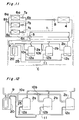
- Fig. 4 is a view showing the schematic construction of the oil level equalizing system according to the third embodiment of the present invention.
- the oil level equalizing system comprises a plurality of low-pressure shell-type compressors 2a, 2b, 2c, oil level equalizing line connecting lines 12a, 12b, 12c arranged for respective compressors 2a, 2b, 2c and each having one end connected to the shell of the corresponding compressor at a location adjacent to the normal oil level within the shell, an oil level equalizing line 11 connected to the other ends of the respective connecting lines 12a, 12b, 12c, an oil/gas separator 23 arranged in the suction line 9 on the upstream side of suction line branch portions 10a, 10b for the respective compressors 2a, 2b, 2c so as to separate oil from a gas refrigerant, an accumulator 20 arranged in the suction line 9 on the upstream side of the separator 23, and a communication line 24 for communicating an upper gas refrigerant portion of the separator 23 with the oil level equalizing line 11 to increase the pressure within the oil level equalizing line 11 higher than the pressures within the shells of the respective compressors 2a,
- the plurality of compressors 2a, 2b, 2c include one or more compressors of different or variable capacities, and that the compressor 2a has a smaller capacity than those of the compressors 2b, 2c.
- the delivery oil quantity and the return oil quantity in the respective compressors 2a, 2b, 2c will be explained hereinafter.
- the oil quantity supplied to a compression chamber of each of the high-capacity compressors 2b, 2c is generally greater than that for the low-capacity compressor 2a, the oil content of the delivered refrigerant of the high-capacity compressors 2b, 2c is higher than that in the low-capacity compressor 2a.
- the quantity of the delivered oil is large.
- the quantity of the oil returned from the suction line 9 is in proportion to the circulating quantity. Accordingly, since the quantity of the returned oil becomes less in comparison with the quantity of the delivered oil, when the non-stop operation is continued (for example, 20 hours), the oil quantity gradually decreases.
- Fig. 5 is a view showing a refrigerating cycle of an air conditioning equipment employing the oil level equalizing system according to the fourth embodiment of the present invention.
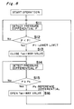
- Fig. 6 is a flow-chart showing a method of controlling a two-way valve mounted in the oil level equalizing system.
- an outdoor unit 1 of an air conditioning equipment comprises a plurality of low-pressure shell-type compressors 2a, 2b, 2c, a four-way valve 3 for switching the flowing direction of refrigerant in accordance with a cooling operation and a heating operation, an outdoor heat exchanger 4 which serves as a condenser during the cooling operation and as an evaporator during the heating operation, and an outdoor expansion valve 5 which does not reduce the pressure during the cooling operation but serves as a pressure reduction unit during the heating operation.
- Each of indoor units 6a, 6b, 6c comprises an indoor expansion valve 7a, 7b or 7c which does not reduce the pressure during the heating operation but serves as a pressure reduction unit during the cooling operation, and an indoor heat exchanger 8a, 8b or 8c which serves as an evaporator during the cooling operation and as a condenser during the heating operation. Further, the outdoor unit 1 is connected to the indoor units 6a, 6b, 6c to thereby constitute a looped refrigerant circuit.
- Reference numeral 9 designates a suction line which communicates with the suction side of the compressors 2a, 2b, 2c, and reference numerals 10a, 10b and 10c designate branch portions of the suction line 9.
- An oil level equalizing line connecting line 12a, 12b, 12c is connected at its one end to each compressor 2a, 2b, 2c at a location adjacent to the normal oil level within its shell with its other end communicating with an oil level equalizing line 11.
- Reference numeral 13 designates a communication line for communicating the suction line 9 on the upstream side of the suction line branch portion 10a, 10b for each compressor 2a, 2b, 2c with the oil level equalizing line 11.
- Reference numeral 14 designate a two-way valve arranged in a midway portion of the communication line 13. When the two-way valve 14 is opened, the pressure within the oil level equalizing line 11 is higher than the pressures within the shells of the respective compressors 2a, 2b, 2c.
- Reference numeral 15 designates a two-way valve control means to close the two-way valve 14 only for a predetermined period of time Tvo when a continuous running time Tr for the cooling or the heating reaches a predetermined time Tro.
- the oil level equalizing system comprises the plurality of low-pressure shell-type compressors 2a, 2b, 2c, the oil level equalizing line connecting lines 12a, 12b, 12c arranged for the respective compressors 2a, 2b, 2c and each having one end communicating with the shell of the corresponding compressor 2a, 2b, 2c at a location adjacent to the normal oil level within the shell, the oil level equalizing line 11 communicating with the other ends of the respective connecting lines 12a, 12b, 12c, and a communication line 13 for communicating the suction line 9 on the upstream side of suction line branch portions 10a, 10b for the respective compressors 2a, 2b, 2c with the oil level equalizing line 11.
- the oil level equalizing system also comprises the two-way valve 14 arranged in the midway portion of the suction line 9 to increase the pressure within the oil level equalizing line 11 during the opening thereof to a value higher than the pressures within the shells of the respective compressors 2a, 2b, 2c, and the two-way valve control means to close the two-way valve 14 only for the certain period of time Tvo when the continuous running time Tr for the cooling or the heating reaches the predetermined time Tro.
- step S1 the continuous running time Tr for the cooling or the heating is first detected.
- step S2 if the continuous running time Tr is shorter than the predetermined upper limit continuous running time Tro, step S1 is resumed. In contrast, if the time Tr is longer than the predetermined upper limit time Tro, the procedure advances to step S3, at which the two-way valve 14 is closed.
- step S4 a closing time Tv of the two-way valve 14 is detected.
- step S5 if the two-way valve closing time Tv detected at step S4 is shorter than the predetermined upper limit two-way valve closing period of time Tvo, step S4 is resumed. In contrast, if the time Tv is longer than the predetermined upper limit time Tvo, the procedure advances to step S6, at which the two-way valve 14 is opened.
- step S7 the continuous running time Tr is returned to zero, and the procedure returns to step S1.
- the plurality of compressors 2a, 2b, 2c include such compressors as to have different capacities or variable capacities, and that the compressor 2a has a smaller capacity than those of the compressors 2b, 2c.
- the two-way valve 14 When the continuous running time Tr for the cooling or the heating reaches the predetermined time Tro, the two-way valve 14 is closed, and the oil is transferred through the oil level equalizing line 11 from the low-capacity compressor 2a having a higher pressure within the shell to the high-capacity compressors 2b, 2c having lower pressures within the shells. Therefore, it becomes possible to prevent oil shortage after a long-time continuous running, which shortage might be caused when the return oil quantity is less than the delivery oil quantity in the high-capacity compressors 2b, 2c.
- the oil quantity supplied to the compression chamber in the high-capacity compressors 2b, 2c is greater than that in the low-capacity compressor 2a
- the oil content within the delivered refrigerant is greater than that in the low-capacity compressor 2a.
- the delivered refrigerants from the respective compressors 2a, 2b, 2c are joined after the delivery, the oil contents within the refrigerants drawn into the respective compressors 2a, 2b, 2c after being divided at the suction line branch portions 10a, 10b are equal to one another. Therefore, since the return oil quantity is less than the delivery oil quantity in each high-capacity compressor 2a, 2b, 2c, when the non-stop operation is continued for a long period of time, the oil quantity gradually decreases and oil shortage occurs before long.
- the two-way valve 14 is closed only for the certain period of time Tvo so that the oil transfers from the low-capacity compressor 2a to the high-capacity compressors 2b, 2c through the oil level equalizing line 11. Therefore, it becomes possible to prevent oil shortage, which may be caused when the return oil quantity is less than the delivery oil quantity, after the long time continuous operation. In this way, the adequate oil quantity can be maintained in each compressor 2a, 2b, 2c.
- this embodiment is provided with the two-way valve 14 arranged at a midway portion of the communication line 13 for increasing the pressure within the oil level equalizing line 11 to a value higher than the pressures within the shells of the respective compressors 2a, 2b, 2c during the valve opening, and with the two-way valve control means 15 adapted to close the two-way valve 14 only for the certain period of time Tvo when the continuous running time Tr for the cooling or the heating reaches the predetermined time Tro.
- this embodiment may be provided, in addition to the construction of the second embodiment, with the two-way valve adapted to increase the pressure within the oil level equalizing line 11 during the opening of the valve arranged in the midway portion of the communication line 22 to a value higher than the pressures within the shells of the respective compressors 2a, 2b, 2c, and with the two-way valve control means adapted to close the two-way valve only for the certain period of time Tvo when the continuous running time Tr for the cooling or the heating has reached the predetermined time Tro.
- this embodiment may be provided, in addition to the construction of the third embodiment, with the two-way valve arranged in the midway portion of the communication line 24 so as to increase the pressure within the equalizing line 11 during the valve opetung to a value higher than the pressures within the shells of the respective compressors 2a, 2b, 2c, and with the two-way valve control means adapted to close the two-way valve only for the certain period of time Tvo when the continuous running time Tr for the cooling or the heating has reached the predetermined time Tro.
- Fig. 7 is a view showing a refrigerating cycle of an air conditioning equipment employing the oil level equalizing system according to the fifth embodiment of the present invention.
- Fig. 8 is a flow-chart showing a method of controlling a two-way valve mounted in the oil level equalizing system.
- an outdoor unit 1 of the air conditioning equipment comprises a plurality of low-pressure shell-type compressors 2a, 2b, 2c, a four-way valve 3 for switching the flowing direction of refrigerant in accordance with a cooling operation and a heating operation, an outdoor heat exchanger 4 which serves as a condenser during the cooling operation and as an evaporator during the heating operation, and an outdoor expansion valve 5 which does not reduce the pressure during the cooling operation but serves as a pressure reduction unit during the heating operation.
- Each of indoor units 6a, 6b, 6c comprises an indoor expansion valve 7a, 7b or 7c which does not reduce the pressure during the heating operation but serves as a pressure reduction unit during the cooling operation, and an indoor heat exchanger 8a, 8b or 8c which serves as an evaporator during the cooling operation and as a condenser during the heating operation. Further, the outdoor unit 1 is connected to the indoor units 6a, 6b, 6c to thereby constitute a looped refrigerant circuit.
- Reference numeral 9 designates a suction line which communicates with the suction side of the compressors 2a, 2b, 2c, and reference numerals 10a, 10b and 10c designate branch portions of the suction line 9.
- An oil level equalizing line connecting line 12a, 12b, 12c is connected at its one end to each compressor 2a, 2b, 2c at a location adjacent to the normal oil level within its shell with its other end communicating with an oil level equalizing line 11.
- Reference numeral 13 designates a communication line for communicating the suction line 9 on the upstream side of the suction line branch portion 10a, 10b for each compressor 2a, 2b, 2c with the oil level equalizing line 11.
- Reference numeral 14 designates a two-way valve arranged in a midway portion of the communication line 13. When the two-way valve 14 is opened, the pressure within the equalizing line 11 is higher than the pressures within the shells of the respective compressors 2a, 2b, 2c.
- Reference numerals 16a, 16b, 16c designate pressure differential detecting units (for example, pressure differential sensors, or two pressure sensors) for detecting the pressure differential between the shell upper portion and the shell lower portion of each compressor 2a, 2b, 2c.
- Reference numeral 17 designates a two-way valve control means which closes the two-way valve 14 when the pressure differential P between the shell upper portion and the shell lower portion detected by at least one of the pressure differential detecting units 16a, 16b, 16c becomes smaller than a predetermined lower limit pressure differential P1, and opens the two-way valve 14 when the pressure differentials P between the shell upper portions and the shell lower portions detected by all the pressure differential detecting units 16a, 16b, 16c become equal to or larger than a predetermined reference pressure differential Ps.
- pressure differential detecting units for example, pressure differential sensors, or two pressure sensors
- the oil level equalizing system comprises the plurality of low-pressure shell-type compressors 2a, 2b, 2c, the oil level equalizing line connecting lines 12a, 12b, 12c arranged for the respective compressors 2a, 2b, 2c and each having one end communicating with the shell of the corresponding compressor 2a, 2b or 2c at a location adjacent to the normal oil level within the shell, the oil level equalizing line 11 communicating with the other ends of the respective connecting lines 12a, 12b, 12c, the communication line 13 for communicating the suction line 9 on the upstream side of suction line branch portions 10a, 10b for the respective compressors 2a, 2b, 2c with the equalizing line 11, and the two-way valve 14 arranged in the midway portion of the suction line 9 to increase the pressure within the oil level equalizing line 11 during the opening thereof to a value higher than the pressures within the shells of the respective compressors 2a, 2b, 2c.
- the oil level equalizing system further comprises the pressure differential detecting units 16a
- step S11 the pressure differentials P between the shell upper portions and the shell lower portions of the compressors 2a, 2b, 2c are detected by the pressure differential detecting units 16a, 16b, 16c, respectively.
- step S12 if the pressure differential P detected at step S11 for at least one of the compressors 2a, 2b, 2c is equal to or larger than the predetermined lower limit pressure differential P1, the procedure returns to step S11. If it is smaller than the predetermined lower limit pressure differential P1, the procedure advances to step S13, at which the two-way valve 14 is closed.
- step S14 the pressure differentials P between the shell upper portions and the shell lower portions of the compressors 2a, 2b, 2c are detected by the pressure differential detecting units 16a, 16b, 16c, respectively.
- step S15 if the pressure differentials P detected at step S14 for all the compressors 2a, 2b, 2c are smaller than the predetermined reference pressure differential Ps, the procedure returns to step S14. If it is equal to or larger than the predetermined reference pressure differential Ps, the procedure advances to step S16, at which the two-way valve 14 is opened. Thereafter, the procedure returns to step S11.
- the plurality of compressors 2a, 2b, 2c include one or more compressors of different capacities or variable capacities, and that the compressor 2a has a smaller capacity than those of the compressors 2b, 2c.
- the two-way valve 14 is closed and the oil transfers through the oil level equalizing line 11 from the low-capacity compressor 2a having the higher pressure within its shell to the high-capacity compressors 2b, 2c having the lower pressures within their shells. Then, when the oil quantities of the compressor 2b, 2c increase and the pressure differentials between the shell upper portions and the shell lower portions thereof become equal to or larger than the reference pressure differential Ps, the two-way valve 14 is opened and the oil transfer through the equalizing line 11 is stopped.
- the oil quantity supplied to the compression chamber in each high-capacity compressor 2b, 2c is greater than that in the low-capacity compressor 2a, the oil content within the delivered refrigerant is larger than that in the low-capacity compressor 2a.
- the delivered refrigerants from the respective compressors 2a, 2b, 2c are joined after the delivery, the oil contents within the refrigerants drawn into the respective compressors 2a, 2b, 2c after being divided at the suction line branch portions 10a, 10b are equal to one another. Therefore, since the return oil quantity is less than the delivery oil quantity in each high-capacity compressor 2b, 2c, when the non-stop operation is continued for a long period of time, the oil quantity gradually decreases and oil shortage occurs before long.
- the two-way valve 14 is closed until the oil quantities increase to such an extent that the pressure differentials P between the shell upper portions and the shell lower portions thereof become equal to or larger than the reference pressure differential Ps. Accordingly, the oil transfers from the low-capacity compressor 2a to the high-capacity compressors 2b, 2c through the oil level equalizing line 11. Therefore, it becomes possible to prevent oil shortage, which has been hitherto caused when the return oil quantity is less than the delivery oil quantity in the high-capacity compressors 2b, 2c, after the long time non-stop running.
- the two-way valve 14 can be controlled accurately without being affected by variations in the oil delivery quantity and the oil return quantity of the compressors 2a, 2b, 2c which may be caused under different operating conditions. Accordingly, it becomes possible to prevent oil shortage in the high-capacity compressors 2b, 2c which would be caused by delayed closing of the two-way valve 14 or early opening of the two-way valve 14 after the closing, and also to prevent oil shortage in the low-capacity compressor 2a which would be caused by early or delayed opening of the two-way valve 14 after the closing. It is therefore possible to maintain the adequate oil quantities in the respective compressors 2a, 2b, 2c.
- This embodiment is provided, in addition to the construction of the first embodiment, with the two-way valve 14 arranged at a midway portion of the communication line 13 for increasing the pressure within the oil level equalizing line 11 to a value higher than the pressures within the shells of the respective compressors 2a, 2b, 2c during the valve opening, the pressure differential detecting units 16a, 16b, 16c for detecting the pressure differential between the shell upper portion and the shell lower portion of each compressor 2a, 2b, 2c, and the two-way valve control means 17 for closing the two-way valve 14 when the pressure differential P between the shell upper portion and the shell lower portion detected by at least one of the pressure differential detecting units 16a, 16b, 16c becomes smaller than the predetermined lower limit pressure differential P1, and for subsequently opening the two-way valve 14 when the pressure differentials P between the shell upper portions and the shell lower portions detected by the pressure differential detecting units 16a, 16b, 16c of all the compressors 2a, 2b, 2c become equal to or larger than the predetermined reference pressure differential Ps
- this embodiment may be provided, in addition to the construction of the second embodiment, with the two-way valve arranged at a midway portion of the communication line 22 for increasing the pressure within the oil level equalizing line 11 to a value higher than the pressures within the shells of the respective compressors 2a, 2b, 2c during the valve opening, the pressure differential detecting units 16a, 16b, 16c for detecting the pressure differential between the shell upper portion and the shell lower portion of each compressor 2a, 2b, 2c, and the two-way valve control means 17 for closing the two-way valve 14 when the pressure differential P between the shell upper portion and the shell lower portion detected by at least one of the pressure differential detecting units 16a, 16b, 16c becomes smaller than the predetermined lower limit pressure differential P1, and for subsequently opening the two-way valve 14 when the pressure differentials P between the shell upper portions and the shell lower portions detected by the pressure differential detecting units 16a, 16b, 16c of all the compressors 2a, 2b, 2c become equal to or larger than the predetermined reference pressure differential
- this embodiment may be provided, in addition to the construction of the third embodiment, with the two-way valve arranged at a midway portion of the communication line 24 for increasing the pressure within the oil level equalizing line 11 to a value higher than the pressures within the shells of the respective compressors 2a, 2b, 2c during the valve opening, the pressure differential detecting units 16a, 16b, 16c for detecting the pressure differential between the shell upper portion and the shell lower portion of each compressor 2a, 2b, 2c, and the two-way valve control means for closing the two-way valve 14 when the pressure differential P between the shell upper portion and the shell lower portion detected by at least one of the pressure differential detecting units 16a, 16b, 16c becomes less than the predetermined lower limit pressure differential P1, and for subsequently opening the two-way valve 14 when the pressure differentials P between the shell upper portions and the shell lower portions detected by the pressure differential detecting units 16a, 16b, 16c of all the compressors 2a, 2b, 2c become equal to or larger than the predetermined reference pressure differential
- Fig. 9 is a view showing a refrigerating cycle of an air conditioning equipment employing the oil level equalizing system according to the sixth embodiment of the present invention.
- Fig. 10 is a flow-chart showing a method of controlling a two-way valve mounted in the oil level equalizing system.
- an outdoor unit 1 of an air conditioning equipment comprises a plurality of low-pressure shell-type compressors 2a, 2b, 2c, a four-way valve 3 for switching the flowing direction of refrigerant in accordance with a cooling operation and a heating operation, an outdoor heat exchanger 4 which serves as a condenser during the cooling operation and as an evaporator during the heating operation, and an outdoor expansion valve 5 which does not reduce the pressure during the cooling operation but serves as a pressure reduction unit during the heating operation.
- Each of indoor units 6a, 6b, 6c comprises an indoor expansion valve 7a, 7b or 7c which does not reduce the pressure during the heating operation but serves as a pressure reduction unit during the cooling operation, and an indoor heat exchanger 8a, 8b or 8c which serves as an evaporator during the cooling operation and as a condenser during the heating operation. Further, the outdoor unit 1 is connected to the indoor units 6a, 6b, 6c to thereby constitute a looped refrigerant circuit.
- Reference numeral 9 designates a suction line which communicates with the suction side of the compressors 2a, 2b, 2c, and reference numerals 10a, 10b and 10c designate branch portions of the suction line 9.
- An oil level equalizing line connecting line 12a, 12b, 12c is connected at its one end to each compressor 2a, 2b, 2c at a location adjacent to the normal oil level within its shell with its other end communicating with an oil level equalizing line 11.
- Reference numeral 13 designates a communication line for communicating the suction line 9 on the upstream side of the suction line branch portion 10a, 10b for each compressor 2a, 2b, 2c with the oil level equalizing line 11.
- Reference numeral 14 designates a two-way valve arranged in a midway portion of the communication line 13. When the two-way valve 14 is opened, the pressure within the equalizing line 11 is higher than the pressures within the shells of the respective compressors 2a, 2b, 2c.
- Reference numerals 18a, 18b, 18c designate oil level detecting units (for example, a plurality of float switches) for detecting oil levels H in the compressors 2a, 2b, 2c.
- Reference numeral 19 designates a two-way valve control means for closing the two-way valve 14 when the oil level H detected by at least one of the oil level detecting units 18a, 18b, 18c becomes lower than a predetermined lower limit oil level Ho and for opening the two-way valve 14 when the oil levels H then detected by the oil level detecting units 18a, 18b, 18c of all the compressors 2a, 2b, 2c become equal to or more than a predetermined reference oil level Hs.
- oil level detecting units for example, a plurality of float switches
- the oil level equalizing system for plural compressors comprises the plurality of low-pressure shell-type compressors 2a, 2b, 2c, the oil level equalizing line connecting lines 12a, 12b, 12c arranged for the respective compressors 2a, 2b, 2c and each having one end communicating with the shell of the corresponding compressor 2a, 2b or 2c at a location adjacent to the normal oil level within the shell, the oil level equalizing line 11 communicating with the other ends of the respective connecting lines 12a, 12b, 12c, a communication line 13 for commumcating the suction line 9 on the upstream side of suction line branch portions 10a, 10b for the respective compressors 2a, 2b, 2c with the oil level equalizing line 11, the two-way valve 14 arranged in the midway portion of the communication line 13 to increase the pressure within the oil level equalizing line 11 during the opening thereof to a value higher than the pressures within the shells of the respective compressors 2a, 2b, 2c, the oil level detecting units
- step S21 the oil levels H in the compressors 2a, 2b, 2c are detected by the oil level detecting units 18a, 18b, 18c, respectively.
- step S22 if the oil level H detected at step S21 for at least one of the compressors 2a, 2b, 2c is equal to or more than the predetermined lower limit oil level Ho, step S21 is resumed. If it is less than the predetermined lower limit oil level Ho, the procedure advances to step S23, at which the two-way valve 14 is closed.
- step S24 the oil levels H in the compressors 2a, 2b, 2c are detected by the oil level detecting units 18a, 18b, 18c, respectively.
- step S25 if the oil levels H in all the compressors 2a, 2b, 2c are less than the predetermined reference oil level Hs, step S24 is resumed. If it is equal to or more than the predetermined reference oil level Hs, the procedure advances to step S26, at which the two-way valve 14 is opened, and the procedure returns to step S21.
- the plurality of compressors 2a, 2b, 2c include such compressors as to have different capacities or variable capacities, and that the compressor 2a has a smaller capacity than those of the compressors 2b, 2c.
- the two-way valve 14 When the oil quantities of the compressors 2b, 2c decrease and the oil levels H thereof become less than the lower limit oil level Ho, the two-way valve 14 is closed and the oil transfers through the oil level equalizing line 11 from the low-capacity compressor 2a having the higher pressure within its shell into the high-capacity compressors 2b, 2c having the lower pressures within their shells. Then, when the oil quantities of the compressor 2b, 2c increase and the oil levels H thereof become equal to or more than the reference oil level Hs, the two-way valve 14 is opened and the oil transfer through the oil level equalizing line 11 is stopped.
- the oil quantity supplied to the compression chamber in the high-capacity compressors 2b, 2c is more than that in the low-capacity compressor 2a
- the oil content within the delivered refrigerant is larger than that in the low-capacity compressor 2a.
- the delivered refrigerants from the respective compressors 2a, 2b, 2c are joined after the delivery, the oil contents within the refrigerants drawn into the respective compressors 2a, 2b, 2c after being divided at the suction line branch portions 10a, 10b are equal to one another. Therefore, since the return oil quantity is less than the delivery oil quantity in each high-capacity compressor 2b, 2c, when the non-stop operation is continued for a long period of time, the oil quantity gradually decreases and oil shortage occurs before long.
- the two-way valve 14 is closed until the oil quantities increase and the oil levels H thereof become equal to or higher than the reference oil level Hs so that the oil transfers from the low-capacity compressor 2a to the high-capacity compressors 2b, 2c through the oil level equalizing line 11. Therefore, it becomes possible to prevent oil shortage, which would be caused when the return oil quantity is less than the delivery oil quantity in the high-capacity compressors 2b, 2c, after the long time non-stop running.
- the two-way valve 14 can be controlled accurately without being affected by variations in the oil delivery quantity and the oil return quantity of the compressors 2a, 2b, 2c which may be caused under different operation conditions. Accordingly, it becomes possible to prevent oil shortage in the high-capacity compressors 2b, 2c which would be caused by delayed closing of the two-way valve 14 or early opening of the two-way valve 14 after the closing, and also to prevent oil shortage in the low-capacity compressor 2a which would be caused by delayed opening of the two-way valve 14 after the closing. In this way, it is possible to maintain the adequate oil quantities in the respective compressors 2a, 2b, 2c.
- This embodiment is provided, in addition to the construction of the first embodiment, with the two-way valve 14 arranged at a midway portion of the communication line 13 for increasing the pressure within the oil level equalizing line 11 to a value higher than the pressures within the shells of the respective compressors 2a, 2b, 2c during the valve opening, the oil level detecting units 18a, 18b, 18c for detecting the oil levels H in the compressors 2a, 2b, 2c, and the two-way valve control means 19 for closing the two-way valve 14 when the oil level H detected by at least one of the oil level detecting units 16a, 16b, 16c becomes lower than the predetermined lower limit oil level Ho and for subsequently opening the two-way valve 14 when the oil levels H detected by the oil level detecting units 16a, 16b, 16c of all the compressors 2a, 2b, 2c become equal to or higher than the predetermined reference oil level Hs.
- this embodiment may be provided, in addition to the construction of the second embodiment, with the two-way valve arranged at a midway portion of the communication line 22 for increasing the pressure within the oil level equalizing line 11 to a value higher than the pressures within the shells of the respective compressors 2a, 2b, 2c during the valve opening, the oil level detecting units 18a, 18b, 18c for detecting the oil levels H in the compressors 2a, 2b, 2c, and the two-way valve control means 19 for closing the two-way valve 14 when the oil level H detected by at least one of the oil level detecting units 16a, 16b, 16c becomes lower than the predetermined lower limit oil level Ho, and for subsequently opening the two-way valve 14 when the oil levels H detected by the oil level detecting units 16a, 16b, 16c of all the compressors 2a, 2b, 2c become equal to or higher than the predetermined reference oil level Hs.
- this embodiment may be provided, in addition to the construction of the third embodiment, with the two-way valve arranged at a midway portion of the communication line 24 for increasing the pressure within the oil level equalizing line 11 to a value higher than the pressures within the shells of the respective compressors 2a, 2b, 2c during the valve opening, the oil level detecting units 18a, 18b, 18c for detecting the oil levels H in the compressors 2a, 2b, 2c, and the two-way valve control means 19 for closing the two-way valve 14 when the oil level H detected by at least one of the oil level detecting units 16a, 16b, 16c becomes lower than the predetermined lower limit oil level Ho, and for subsequently opening the two-way valve 14 when the oil levels H detected by the oil level detecting units 16a, 16b, 16c of all the compressors 2a, 2b, 2c become equal to or higher than the predetermined reference oil level Hs.
- Fig. 11 is a view showing a refrigerating cycle of an air conditioning equipment employing the oil level equalizing system according to the seventh embodiment of the present invention.
- Fig. 12 is a detailed view of a portion denoted by C in Fig. 11.
- an outdoor unit 1 of the air conditioning equipment comprises a plurality of low-pressure shell-type compressors 2a, 2b, 2c, a four-way valve 3 for switching the flowing direction of refrigerant in accordance with a cooling operation and a heating operation, an outdoor heat exchanger 4 which serves as a condenser during the cooling operation and as an evaporator during the heating operation, and an outdoor expansion valve 5 which does not reduce the pressure during the cooling operation but serves as a pressure reduction unit during the heating operation.
- Each of indoor units 6a, 6b, 6c comprises an indoor expansion valve 7a, 7b or 7c which does not reduce the pressure during the heating operation but serves as a pressure reduction unit during the cooling operation, and an indoor heat exchanger 8a, 8b or 8c which serves as an evaporator during the cooling operation and as a condenser during the heating operation. Further, the outdoor unit 1 is connected to the indoor units 6a, 6b, 6c to thereby constitute a looped refrigerant circuit.
- Reference numeral 9 designates a suction line which communicates with the suction side of the compressors 2a, 2b, 2c, and reference numerals 10a, 10b and 10c designate branch portions of the suction line 9.
- An oil level equalizing line connecting line 12a, 12b, 12c is connected at its one end to each compressor 2a, 2b, 2c at a location adjacent to the normal oil level within its shell with its other end communicating with an oil level equalizing line 11.
- Reference numeral 20 designates an accumulator arranged in the suction line 9 on the upstream side of the suction line branch portion 10a, 10b for each compressor 2a, 2b, 2c.
- Reference numeral 25 designates a communication line for increasing the pressure within the oil level equalizing line 11 to a value higher than the pressures within the shells of the respective compressors 2a, 2b, 2c by communicating an upper gas refrigerant portion of the accumulator 20 with the equalizing line 11.
- the oil level equalizing system comprises the plurality of low-pressure shell-type compressors 2a, 2b, 2c, the oil level equalizing line connecting lines 12a, 12b, 12c arranged for the respective compressors 2a, 2b, 2c and each having one end communicating with the shell of the corresponding compressor 2a, 2b, 2c at a location adjacent to the normal oil level within the shell, the oil level equalizing line 11 communicating with the other ends of the respective connecting lines 12a, 12b, 12c, the accumulator 20 arranged in the suction line 9 on the upstream side of the suction line branch portion 10a, 10b for each compressor 2a, 2b, 2c, and the communication line 25 for increasing the pressure within the oil level equalizing line 11 to a value higher than the pressures within the shells of the respective compressors 2a, 2b, 2c by communicating the upper gas refrigerant portion of the accumulator 20 with the equalizing line 11.
- the plurality of compressors 2a, 2b, 2c include one or more compressors of different capacities or variable capacities and that the compressor 2a has a smaller capacity than those of the compressors 2b, 2c.
- the inlet port of the communication line 25 is located at an upper portion within the accumulator 20 within which only the gas refrigerant from which the oil is separated exists, only the gas refrigerant containing no oil flows through the communication line 25.
- each high-capacity compressor 2b, 2c When studying the delivery oil quantity in the absence of the oil transfer, since the oil quantity supplied to a compression chamber of each high-capacity compressor 2b, 2c is generally more than that for the low-capacity compressor 2a, the oil content of the delivered refrigerant thereof is higher than that in the low-capacity compressor 2a.
- the return oil quantity since the oil contents of the refrigerants in the suction lines 9 to the respective compressors 2a, 2b, 2c are equal to one another, the return oil quantities to the respective compressors 2a, 2b, 2c are in proportion to circulating refrigerant quantities in the respective compressors 2a, 2b, 2c.
- the oil quantity of the delivered refrigerant in each high-capacity compressor 2b, 2c is high, the quantity of the delivered oil is large.
- the oil quantity returned from the suction line 9 is in proportion to the circulating quantity. Accordingly, the returned oil quantity is less than the delivered oil quantity and, hence, when the non-stop operation is continued (for example, 20 hours), the oil quantity gradually decreases.
- the pressure within the equalizing line 11 becomes higher than those within the shells of the respective compressors 2a, 2b, 2c so that the oils in the respective compressors 2a, 2b, 2c do not transfer to the equalizing line 11.
- Fig. 13 is a view showing a refrigerating cycle of an air conditioning equipment employing the oil level equalizing system according to the eighth embodiment of the present invention.
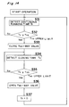
- Fig. 14 is a flow-chart showing a method of controlling a two-way valve mounted in the oil level equalizing system.
- an outdoor unit 1 of the air conditioning equipment comprises a plurality of low-pressure shell-type compressors 2a, 2b, 2c, a four-way valve 3 for switching the flowing direction of refrigerant in accordance with a cooling operation and a heating operation, an outdoor heat exchanger 4 which serves as a condenser during the cooling operation and as an evaporator during the heating operation, and an outdoor expansion valve 5 which does not reduce the pressure during the cooling operation but serves as a pressure reduction unit during the heating operation.
- Each of indoor units 6a, 6b, 6c comprises an indoor expansion valve 7a, 7b or 7c which does not reduce the pressure during the heating operation but serves as a pressure reduction unit during the cooling operation, and an indoor heat exchanger 8a, 8b or 8c which serves as an evaporator during the cooling operation and as a condenser during the heating operation. Further, the outdoor unit 1 is connected to the indoor units 6a, 6b, 6c to thereby constitute a looped refrigerant circuit.
- Reference numeral 9 designates a suction line which communicates with the suction side of the compressors 2a, 2b, 2c, and reference numerals 10a, 10b and 10c designate branch portions of the suction line 9.
- An oil level equalizing line connecting line 12a, 12b, 12c is connected at its one end to each compressor 2a, 2b, 2c at a location adjacent to the normal oil level within its shell with its other end communicating with an oil level equalizing line 11.
- Reference numeral 20 designates an accumulator arranged in the suction line 9 on the upstream side of the suction line branch portion 10a, 10b for each compressor 2a, 2b, 2c.
- Reference numeral 25 designates a communication line for communicating the upper gas refrigerant portion within the accumulator 20 with the oil level equalizing line 11.
- Reference numeral 14 designates a two-way valve arranged in a midway portion of the communication line 25.
- Reference numeral 15 designates a two-way valve control means for closing the two-way valve 14 only for a certain period of time Tvo when the continuous running time Tr for the cooling or the heating has reached a predetermined time Tro.
- the oil level equalizing system comprises the plurality of low-pressure shell-type compressors 2a, 2b, 2c, the oil level equalizing line connecting lines 12a, 12b, 12c arranged for the respective compressors 2a, 2b, 2c and each having one end communicating with the shell of the corresponding compressor 2a, 2b or 2c at a location adjacent to the normal oil level within the shell, the oil level equalizing line 11 communicating with the other ends of the respective connecting lines 12a, 12b, 12c, the accumulator 20 arranged in the suction line 9 on the upstream side of the suction line branch portion 10a, 10b for each compressor 2a, 2b, 2c, the communication line 25 for communicating the upper gas refrigerant portion within the accumulator 20 with the oil level equalizing line 11, the two-way valve 14 arranged in a midway portion of the communication line 25 so as to increase the pressure within the oil level equalizing line 11 to a value higher than the pressures within the shells of the respective compressors 2a, 2
- step S31 the continuous running time Tr for cooling or the heating is detected.
- step S32 if the continuous running time Tr detected at step S31 is less than a predetermined upper limit continuous running time Tro, the procedure returns to step S31. If it is equal to or more than the predetermined upper limit continuous running time Tro, the procedure advances to step S33, at which the two-way valve 14 is closed.
- step S34 a closing time Tv of the two-way valve 14 is detected.
- step S35 if the two-way valve closing time Tv detected at step S34 is less than the predetermined upper limit two-way valve closing time Tvo, the procedure returns to step S34.
- step S36 the procedure advances to step S36, at which the two-way valve 14 is opened.
- step S37 the continuous running time Tr is returned to zero, and step S31 is resumed.
- the plurality of compressors 2a, 2b, 2c include one or more compressors of different capacities or variable capacities and that the compressor 2a has a smaller capacity than those of the compressors 2b, 2c.
- the inlet of the communication line 25 is located at the upper portion within the accumulator 20 within which only the gas refrigerant from which the oil has been separated exists, only the gas refrigerant not containing any oil flows through the communication line 25.
- the two-way valve 14 When the continuous running time Tr for the cooling or the heating reaches the predetermined time Tro, the two-way valve 14 is closed so that the oil transfers through the oil level equalizing line 11 from the low-capacity compressor 2a having a high pressure within its shell into the high-capacity compressors 2b, 2c having a low pressure within their shells. Then, when the predetermined time Tvo passes after the two-way valve 14 has closed, the two-way valve 14 is opened to prevent the oil from transferring through the oil level equalizing line 11.
- the oil quantity supplied to the compression chamber in the high-capacity compressors 2b, 2c is more than that in the low-capacity compressor 2a
- the oil content of the delivered refrigerant is larger than that of the low-capacity compressor 2a.
- the delivered refrigerants from the respective compressors 2a, 2b, 2c are joined after the delivery, the oil contents within the refrigerants drawn into the respective compressors 2a, 2b, 2c after being divided at the suction line branch portions 10a, 10b are equal to one another. Therefore, since the return oil quantity is less than the delivery oil quantity in each high-capacity compressor 2b, 2c, when the non-stop operation is continued for a long period of time, the oil quantity gradually decreases and oil shortage occurs before long.
- the two-way valve 14 is closed only for the predetermined time Tvo so that the oil transfers from the low-capacity compressor 2a to the high-capacity compressors 2b, 2c through the oil level equalizing line 11 while the compressors 2a, 2b, 2c are running and the two-way valve 14 is opened. Accordingly, it becomes possible to prevent oil shortage, which would be caused when the return oil quantity is less than the oil delivery quantity in the high-capacity compressors 2b, 2c, after the long time continuous operation. In this way, it becomes possible to maintain the adequate oil quantity in each compressor 2a, 2b, 2c.
- Fig. 15 is a view showing a refrigerating cycle of an air conditioning equipment employing the oil level equalizing system according to the ninth embodiment of the present invention
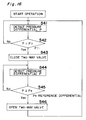
- Fig. 16 is a flow-chart showing a method of controlling a two-way valve mounted in the oil level equalizing system.
- an outdoor unit 1 of the air conditioning equipment comprises a plurality of low-pressure shell-type compressors 2a, 2b, 2c, a four-way valve 3 for switching the flowing direction of refrigerant in accordance with a cooling operation and a heating operation, an outdoor heat exchanger 4 which serves as a condenser during the cooling operation and as an evaporator during the heating operation, and an outdoor expansion valve 5 which does not reduce the pressure during the cooling operation but serves as a pressure reduction unit during the heating operation.
- Each of indoor units 6a, 6b, 6c comprises an indoor expansion valve 7a, 7b or 7c which does not reduce the pressure during the heating operation but serves as a pressure reduction unit during the cooling operation, and an indoor heat exchanger 8a, 8b or 8c which serves as an evaporator during the cooling operation and as a condenser during the heating operation. Further, the outdoor unit 1 is connected to the indoor units 6a, 6b, 6c to thereby constitute a looped refrigerant circuit.
- Reference numeral 9 designates a suction line which communicates with the suction side of the compressors 2a, 2b, 2c, and reference numerals 10a, 10b and 10c designate branch portions of the suction line 9.
- An oil level equalizing line connecting line 12a, 12b, 12c is connected at its one end to each compressor 2a, 2b, 2c at a location adjacent to the normal oil level within its shell with its other end communicating with an oil level equalizing line 11.
- Reference numeral 20 designates an accumulator arranged in the suction line 9 on the upstream side relative to the suction line branch portion 10a, 10b for each compressor 2a, 2b, 2c.
- Reference numeral 25 designates a communication line for communicating the upper gas refrigerant portion within the accumulator 20 with the oil level equalizing line 11.
- Reference numeral 14 designates a two-way valve arranged in a midway portion of the communication line 25.
- Reference numerals 16a, 16b, 16c designate pressure differential detecting units (for example, pressure differential sensors or two pressure sensors) for detecting the pressure differentials between the shell upper portions and the shell lower portions of the compressors 2a, 2b, 2c.
- Reference numeral 17 designates a two-way valve control means for closing the two-way valve 14 when the pressure differential P between the shell upper portion and the shell lower portion detected by at least one of the pressure differential detecting units 16a, 16b, 16c becomes smaller than a predetermined lower limit pressure differential P1 and for subsequently opening the two-way valve 14 when the pressure differentials P between the shell upper portions and the shell lower portions detected by the pressure differential detecting units 16a, 16b, 16c of all the compressors 2a, 2b, 2c become equal to or larger than a predetermined reference pressure differential Ps.
- the oil level equalizing system comprises the plurality of low-pressure shell-type compressors 2a, 2b, 2c, the oil level equalizing line connecting lines 12a, 12b, 12c arranged for the respective compressors 2a, 2b, 2c and each having one end communicating with the shell of the corresponding compressor 2a, 2b or 2c at a location adjacent to the normal oil level within the shell, the oil level equalizing line 11 communicating with the other ends of the respective connecting lines 12a, 12b, 12c, the accumulator 20 arranged in the suction line 9 on the upstream side relative to the suction line branch portion 10a, 10b for each compressor 2a, 2b, 2c, the communication line 25 for communicating the upper gas refrigerant portion within the accumulator 20 with the oil level equalizing line 11, the two-way valve 14 arranged in the midway portion of the communication line 25 to increase the pressure within the oil level equalizing line 11 to a value higher than those within the shells of the respective compressors 2a, 2b, 2c
- the pressure differential detecting units 16a, 16b, 16c detect the pressure differentials P between the shell upper portions and the shell lower portions of the compressors 2a, 2b, 2c.
- step S42 if the pressure differential P detected at step S41 for at least one of the compressors 2a, 2b, 2c is equal to or larger than the predetermined lower limit pressure differential P1, step S41 is resumed. In contrast, if it is smaller than the predetermined lower limit pressure differential P1, the procedure advances to step S43, at which the two-way valve 14 is closed.
- the pressure differential detecting units 16a, 16b, 16c detect the pressure differentials P between the shell upper portions and the shell lower portions of the compressors 2a, 2b, 2c.
- step S45 if the pressure differential P detected at step S44 for all the compressors 2a, 2b, 2c is smaller than the predetermined reference pressure differential Ps, step S44 is resumed. If it is equal to or larger than the predetermined reference pressure differential Ps, the procedure advances to step S46, at which the two-way valve 14 is opened, and the procedure returns to step S41.
- the plurality of compressors 2a, 2b, 2c include one or more compressors of different capacities or variable capacities and that the compressor 2a has a smaller capacity than those of the compressors 2b, 2c.
- the inlet of the communication line 25 is located in the upper portion within the accumulator 20 within which only the gas refrigerant from which the oil has been separated exists, only the gas refrigerant containing no oil flows through the communication line 25.
- the two-way valve 14 is opened and the oil is prevented from transferring through the equalizing line 11.
- the oil quantity supplied to the compression chamber in the high-capacity compressors 2b, 2c is greater than that in the low-capacity compressor 2a
- the oil content of the delivered refrigerant is greater than that of the high-capacity compressor 2a.
- the refrigerants delivered from the respective compressors 2a, 2b, 2c are joined after the delivery, the oil contents within the refrigerants drawn into the respective compressors 2a, 2b, 2c after being divided at the suction line branch portions 10a, 10b are equal to one another. Therefore, since the return oil quantity is less than the delivery oil quantity in each high-capacity compressor 2b, 2c, when the non-stop operation is continued for a long period of time, the oil quantity gradually decreases and oil shortage occurs before long.
- the two-way valve 14 is closed until the oil quantities increase and the pressure differentials P between the shell upper portions and the shell lower portions thereof become equal to or larger than the reference pressure differential Ps, so that the oil transfers from the low-capacity compressor 2a to the high-capacity compressors 2b, 2c through the oil level equalizing line 11. Therefore, it becomes possible to prevent oil shortage, which would be caused when the return oil quantity is less than the delivery oil quantity in the high-capacity compressors 2b, 2c, after the long time non-stop running.
- the two-way valve 14 can be controlled accurately without being affected by variations in the oil delivery quantity and the oil return quantity of the compressors 2a, 2b, 2c which may be caused under different operation conditions. Accordingly, it becomes possible to prevent oil shortage in the high-capacity compressors 2b, 2c which would be caused by delayed closing of the two-way valve 14 or early opening of the two-way valve 14 after the closing, and also to prevent oil shortage in the low-capacity compressor 2a which would be caused by delayed or early opening of the two-way valve 14 after the closing. In this way, it is possible to maintain the adequate oil quantities in the respective compressors 2a, 2b, 2c.
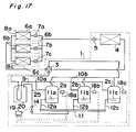
- Fig. 17 is a view showing a refrigerating cycle of an air conditioning equipment employing the oil level equalizing system according to the tenth embodiment of the present invention
- Fig. 18 is a flow-chart showing a method of controlling a two-way valve mounted in the oil level equalizing system.
- an outdoor unit 1 of the air conditioning equipment comprises a plurality of low-pressure shell-type compressors 2a, 2b, 2c, a four-way valve 3 for switching the flowing direction of refrigerant in accordance with a cooling operation and a heating operation, an outdoor heat exchanger 4 which serves as a condenser during the cooling operation and as an evaporator during the heating operation, and an outdoor expansion valve 5 which does not reduce the pressure during the cooling operation but serves as a pressure reduction unit during the heating operation.
- Each of indoor units 6a, 6b, 6c comprises an indoor expansion valve 7a, 7b or 7c which does not reduce the pressure during the heating operation but serves as a pressure reduction unit during the cooling operation, and an indoor heat exchanger 8a, 8b or 8c which serves as an evaporator during the cooling operation and as a condenser during the heating operation. Further, the outdoor unit 1 is connected to the indoor units 6a, 6b, 6c to thereby constitute a looped refrigerant circuit.
- Reference numeral 9 designates a suction line which communicates with the suction side of the compressors 2a, 2b, 2c, and reference numerals 10a, 10b and 10c designate branch portions of the suction line 9.
- An oil level equalizing line connecting line 12a, 12b, 12c is connected at its one end to each compressor 2a, 2b, 2c at a location adjacent to the normal oil level within its shell with its other end communicating with an oil level equalizing line 11.
- Reference numeral 20 designates an accumulator arranged in the suction line 9 on the upstream side relative to the suction line branch portion 10a, 10b for each compressor 2a, 2b, 2c.
- Reference numeral 25 designates a communication line for communicating the upper gas refrigerant portion within the accumulator 20 with the oil level equalizing line 11.
- Reference numeral 14 designates a two-way valve arranged in a midway portion of the communication line 25.
- Reference numerals 18a, 18b, 18c designate oil level detecting units (for example, a plurality of float switches) for detecting oil levels H in the compressors 2a, 2b, 2c.
- Reference numeral 19 designates a two-way valve control means for closing the two-way valve 14 when the oil level H detected by at least one of the oil level detecting units 16a, 16b, 16c becomes lower than a predetermined lower limit oil level Ho and for subsequently opening the two-way valve 14 when the oil levels H detected by the oil level detecting units 16a, 16b, 16c of all the compressors 2a, 2b, 2c become equal to or higher than a predetermined reference oil level Hs.
- the oil level equalizing system for plural compressors comprises the plurality of low-pressure shell-type compressors 2a, 2b, 2c, the oil level equalizing line connecting lines 12a, 12b, 12c arranged for the respective compressors 2a, 2b, 2c and each having one end communicating with the shell of the corresponding compressor 2a, 2b or 2c at a location adjacent to the normal oil level within the shell, the oil level equalizing line 11 communicating with the other ends of the respective connecting lines 12a, 12b, 12c, the accumulator 20 arranged in the suction line 9 on the upstream side relative to the suction line branch portion 10a, 10b for each compressor 2a, 2b, 2c, the communication line 25 for communicating the upper gas refrigerant portion within the accumulator 20 with the oil level equalizing line 11, the two-way valve 14 arranged in a midway portion of the communication line 25 so as to increase the pressure within the oil level equalizing line 11 to a value higher than those within the shells of the respective compressor
- step S51 the oil levels H in the compressors 2a, 2b, 2c are detected by the oil level detecting units 18a, 18b, 18c, respectively.
- step S52 if the oil level H detected at step S51 for at least one of the compressors 2a, 2b, 2c is equal to or higher than the predetermined lower limit oil level Ho, step S51 is resumed. In contrast, if it is lower than the predetermined lower limit oil level Ho, the procedure advances to step S53, at which the two-way valve 14 is closed.
- step S54 the oil levels H in the compressors 2a, 2b, 2c are detected by the oil level detecting units 18a, 18b, 18c, respectively.
- step S55 if the oil levels H for all the compressors 2a, 2b, 2c are lower than the predetermined reference oil level Hs, step S54 is resumed. If it is equal to or higher than the predetermined reference oil level Hs, the procedure advances to step S56, at which the two-way valve 14 is opened, and the procedure returns to step S51.
- the plurality of compressors 2a, 2b, 2c include one or more compressors of different capacities or variable capacities and that the compressor 2a has a smaller capacity than those of the compressors 2b, 2c.
- the inlet of the communication line 25 is located at the upper portion within the accumulator 20 within which only the gas refrigerant from which the oil has been separated exists, only the gas refrigerant containing no oil flows through the communication line 25.
- the two-way valve 14 When the oil quantities of the compressors 2b, 2c decrease and the oil levels H thereof become lower than the lower limit oil level Ho, the two-way valve 14 is closed and the oil transfers through the oil level equalizing line 11 from the low-capacity compressor 2a having the higher pressure within its shell into the high-capacity compressors 2b, 2c having the lower pressures within their shells. Then, when the oil quantities of the compressor 2b, 2c increase and the oil levels H thereof become equal to or higher than the reference oil level Hs, the two-way valve 14 is opened and the oil transfer through the equalizing line 11 is stopped.
- the oil quantity supplied to the compression chamber in the high-capacity compressors 2b, 2c is greater than that in the low-capacity compressor 2a, the oil content within the delivered refrigerant therein is larger than that in the low-capacity compressor 2a.
- the delivered refrigerants from the respective compressors 2a, 2b, 2c are joined after the delivery, the oil contents within the refrigerants drawn into the respective compressors 2a, 2b, 2c after being divided at the suction line branch portions 10a, 10b are equal to one another. Therefore, since the return oil quantity is less than the delivery oil quantity in each high-capacity compressor 2b, 2c, when the non-stop operation is continued for a long period of time, the oil quantity gradually decreases and oil shortage occurs before long.
- the two-way valve 14 is closed until the oil quantities increase and the oil levels H thereof become equal to or higher than the reference oil level Hs, so that the oil transfers from the low-capacity compressor 2a to the high-capacity compressors 2b, 2c through the oil level equalizing line 11. Therefore, it becomes possible to prevent oil shortage, which would be caused when the return oil quantity is less than the delivery oil quantity in the high-capacity compressors 2b, 2c, after the long time non-stop running.
- the two-way valve 14 can be controlled accurately without being affected by variations in the oil delivery quantity and the oil return quantity of the compressors 2a, 2b, 2c which may be caused under different operating conditions. Accordingly, it becomes possible to prevent oil shortage in the high-capacity compressors 2b, 2c which would be caused by delayed closing of the two-way valve 14 or early opening of the two-way valve 14 after the closing and also to prevent oil shortage in the low-capacity compressor 2a which would be caused by early or delayed opening of the two-way valve 14 after the closing. In this way, it is possible to maintain the adequate oil quantities in the respective compressors 2a, 2b, 2c.
- the oil level equalizing system has been described as comprising three compressors 2a, 2b, 2c, the present invention is not limited to such cases, but can be applied to the cases employing at least two compressors.
Landscapes
- Engineering & Computer Science (AREA)
- General Engineering & Computer Science (AREA)
- Mechanical Engineering (AREA)
- Physics & Mathematics (AREA)
- Thermal Sciences (AREA)
- Compressors, Vaccum Pumps And Other Relevant Systems (AREA)
- Air Conditioning Control Device (AREA)
Applications Claiming Priority (4)
| Application Number | Priority Date | Filing Date | Title |
|---|---|---|---|
| JP284862/96 | 1996-10-28 | ||
| JP8284862A JPH10132397A (ja) | 1996-10-28 | 1996-10-28 | 空気調和機 |
| JP8311631A JPH10153355A (ja) | 1996-11-22 | 1996-11-22 | 空気調和機 |
| JP311631/96 | 1996-11-22 |
Publications (2)
| Publication Number | Publication Date |
|---|---|
| EP0838640A2 true EP0838640A2 (fr) | 1998-04-29 |
| EP0838640A3 EP0838640A3 (fr) | 1998-06-17 |
Family
ID=26555634
Family Applications (1)
| Application Number | Title | Priority Date | Filing Date |
|---|---|---|---|
| EP97112592A Ceased EP0838640A3 (fr) | 1996-10-28 | 1997-07-23 | Système d'équilibrage du niveau d'huile pour plusieurs compresseurs |
Country Status (4)
| Country | Link |
|---|---|
| US (1) | US5996363A (fr) |
| EP (1) | EP0838640A3 (fr) |
| KR (1) | KR100242810B1 (fr) |
| CA (1) | CA2217514A1 (fr) |
Cited By (14)
| Publication number | Priority date | Publication date | Assignee | Title |
|---|---|---|---|---|
| WO2000042347A1 (fr) * | 1999-01-09 | 2000-07-20 | Sms Schloemann-Siemag Aktiengesellschaft | Systeme de circulation d'huile de graissage |
| WO2001053757A1 (fr) * | 2000-01-21 | 2001-07-26 | Toshiba Carrier Corporation | Detecteur de quantite d'huile, dispositif de refrigeration et conditionneur d'air |
| EP1139038A1 (fr) * | 2000-03-29 | 2001-10-04 | Linde Aktiengesellschaft | Installation frigorifique |
| WO2003064934A1 (fr) | 2002-01-25 | 2003-08-07 | Toshiba Carrier Corporation | Climatiseur |
| EP1548379A1 (fr) * | 2003-12-24 | 2005-06-29 | Samsung Electronics Co., Ltd. | Appareil frigorifique et méthode de côntrole associée |
| EP1666813A1 (fr) * | 2004-11-17 | 2006-06-07 | LG Electronics Inc. | Climatiseur à unités multiples et méthode pour distribuer l'huile uniformément |
| EP1659351A3 (fr) * | 2004-11-19 | 2006-07-26 | LG Electronics Inc. | Système de récupération d'huile et climatiseur à unités multiples associé à ce système |
| CN100360877C (zh) * | 2005-01-11 | 2008-01-09 | 三星电子株式会社 | 制冷系统 |
| WO2009049649A1 (fr) * | 2007-10-18 | 2009-04-23 | Carrier Corporation | Ensemble de compresseurs à piston et procédé d'appoint d'huile |
| EP1510693A3 (fr) * | 2003-08-29 | 2009-09-23 | Samsung Electronics Co., Ltd. | Système d'équilibrage du niveau d'huile pour plusieurs compresseurs |
| CN102278837A (zh) * | 2011-01-28 | 2011-12-14 | 大连三洋压缩机有限公司 | 一种压缩机组均油系统 |
| EP1120611A4 (fr) * | 1999-07-21 | 2012-05-23 | Daikin Ind Ltd | Dispositif refrigerant |
| FR2985552A1 (fr) * | 2012-01-11 | 2013-07-12 | Danfoss Commercial Compressors | Systeme thermodynamique |
| EP2492613A4 (fr) * | 2009-10-22 | 2016-08-17 | Mitsubishi Electric Corp | Dispositif de conditionnement d'air |
Families Citing this family (30)
| Publication number | Priority date | Publication date | Assignee | Title |
|---|---|---|---|---|
| US6553778B2 (en) * | 2001-01-16 | 2003-04-29 | Emerson Electric Co. | Multi-stage refrigeration system |
| EP2112444B1 (fr) * | 2001-06-26 | 2011-03-09 | Daikin Industries, Ltd. | Appareil de réfrigération |
| JP4300804B2 (ja) * | 2002-06-11 | 2009-07-22 | ダイキン工業株式会社 | 圧縮機構の均油回路、冷凍装置の熱源ユニット及びそれを備えた冷凍装置 |
| JP3940840B2 (ja) * | 2002-11-22 | 2007-07-04 | ダイキン工業株式会社 | 空気調和装置 |
| KR100504900B1 (ko) * | 2003-10-10 | 2005-07-29 | 엘지전자 주식회사 | 4대의 압축기를 구비한 공기조화기 및 그의 균유운전 제어방법 |
| JP3939314B2 (ja) * | 2004-06-10 | 2007-07-04 | 三星電子株式会社 | 空気調和装置及びその均油運転方法 |
| JP4811167B2 (ja) * | 2006-07-24 | 2011-11-09 | ダイキン工業株式会社 | 空気調和システム |
| KR100878819B1 (ko) * | 2007-03-02 | 2009-01-14 | 엘지전자 주식회사 | 공기조화기 및 그 제어방법 |
| KR101452767B1 (ko) | 2010-04-01 | 2014-10-21 | 엘지전자 주식회사 | 압축기의 오일 레벨 감지수단 |
| KR101495186B1 (ko) * | 2010-04-01 | 2015-02-24 | 엘지전자 주식회사 | 복수 개의 압축기를 구비한 공기조화기 및 그의 운전방법 |
| CN103851830B (zh) * | 2012-12-03 | 2016-08-17 | 丹佛斯(天津)有限公司 | 油平衡装置和制冷设备 |
| EP2969613B1 (fr) | 2013-03-13 | 2018-08-08 | Bergstrom, Inc. | Système de climatisation utilisant une ventilation à récupération de chaleur pour une commande d'alimentation en air frais et de climatisation |
| CN104457030B (zh) * | 2013-09-13 | 2017-08-25 | 约克广州空调冷冻设备有限公司 | 用于并联式空调机组的油路系统及并联式空调机组 |
| EP3065959B1 (fr) | 2013-11-04 | 2020-06-10 | Bergstrom, Inc. | Système de climatisation extra-plat |
| US9783024B2 (en) | 2015-03-09 | 2017-10-10 | Bergstrom Inc. | System and method for remotely managing climate control systems of a fleet of vehicles |
| US9874384B2 (en) | 2016-01-13 | 2018-01-23 | Bergstrom, Inc. | Refrigeration system with superheating, sub-cooling and refrigerant charge level control |
| US10760831B2 (en) * | 2016-01-22 | 2020-09-01 | Bitzer Kuehlmaschinenbau Gmbh | Oil distribution in multiple-compressor systems utilizing variable speed |
| US10589598B2 (en) | 2016-03-09 | 2020-03-17 | Bergstrom, Inc. | Integrated condenser and compressor system |
| US10081226B2 (en) | 2016-08-22 | 2018-09-25 | Bergstrom Inc. | Parallel compressors climate system |
| US12420616B2 (en) | 2016-08-22 | 2025-09-23 | Bergstrom, Inc. | Multi-compressor oil migration mitigation climate system |
| US10562372B2 (en) | 2016-09-02 | 2020-02-18 | Bergstrom, Inc. | Systems and methods for starting-up a vehicular air-conditioning system |
| US10675948B2 (en) | 2016-09-29 | 2020-06-09 | Bergstrom, Inc. | Systems and methods for controlling a vehicle HVAC system |
| US10369863B2 (en) | 2016-09-30 | 2019-08-06 | Bergstrom, Inc. | Refrigerant liquid-gas separator with electronics cooling |
| US10724772B2 (en) | 2016-09-30 | 2020-07-28 | Bergstrom, Inc. | Refrigerant liquid-gas separator having an integrated check valve |
| WO2018116407A1 (fr) * | 2016-12-21 | 2018-06-28 | 三菱電機株式会社 | Dispositif à cycle de réfrigération |
| US11448441B2 (en) | 2017-07-27 | 2022-09-20 | Bergstrom, Inc. | Refrigerant system for cooling electronics |
| US11420496B2 (en) | 2018-04-02 | 2022-08-23 | Bergstrom, Inc. | Integrated vehicular system for conditioning air and heating water |
| US11460224B2 (en) * | 2018-10-31 | 2022-10-04 | Emerson Climate Technologies, Inc. | Oil control for climate-control system |
| US12422173B2 (en) | 2022-08-19 | 2025-09-23 | Copeland Lp | Multiple-compressor system with oil balance control |
| FR3150576B1 (fr) * | 2023-06-29 | 2025-07-11 | Danfoss Commercial Compressors | Procédé de gestion d’huile dans un système de réfrigération à compresseurs multiples utilisant des dispositifs de détection de niveau d’huile |
Citations (1)
| Publication number | Priority date | Publication date | Assignee | Title |
|---|---|---|---|---|
| JPH0419675U (fr) | 1990-06-11 | 1992-02-19 |
Family Cites Families (11)
| Publication number | Priority date | Publication date | Assignee | Title |
|---|---|---|---|---|
| US4478050A (en) * | 1982-11-19 | 1984-10-23 | Hussmann Corporation | Oil separation for refrigeration system |
| US4589263A (en) * | 1984-04-12 | 1986-05-20 | Hussmann Corporation | Multiple compressor oil system |
| JPS61143659A (ja) * | 1984-12-18 | 1986-07-01 | 三菱電機株式会社 | 冷凍サイクル装置 |
| US4621505A (en) * | 1985-08-01 | 1986-11-11 | Hussmann Corporation | Flow-through surge receiver |
| SE463380B (sv) * | 1988-07-08 | 1990-11-12 | Olson Ref H Olson Refrigeratio | Mellankylaggregat med oljeseparator vid kyl- och frysanlaeggningar |
| JPH0419675A (ja) * | 1990-05-14 | 1992-01-23 | Ricoh Co Ltd | 湿式現像方式の画像形成装置 |
| US5327997A (en) * | 1993-01-22 | 1994-07-12 | Temprite, Inc. | Lubrication management system |
| US5321956A (en) * | 1993-05-26 | 1994-06-21 | Kemp Industrial Refrigeration, Inc. | Oil management and removal system for a refrigeration installation |
| EP0726930B1 (fr) * | 1993-11-06 | 1999-01-20 | Castrol Limited | Lubrification de compresseurs de refrigeration |
| AUPM630094A0 (en) * | 1994-06-17 | 1994-07-14 | Refrigerant Monitoring Systems Pty Ltd | Oil level control device |
| US5542499A (en) * | 1995-01-11 | 1996-08-06 | Ac&R Components, Inc. | Electromechanical oil level regulator |
-
1997
- 1997-07-23 EP EP97112592A patent/EP0838640A3/fr not_active Ceased
- 1997-08-04 US US08/905,729 patent/US5996363A/en not_active Expired - Fee Related
- 1997-10-06 CA CA002217514A patent/CA2217514A1/fr not_active Abandoned
- 1997-10-28 KR KR1019970055536A patent/KR100242810B1/ko not_active Expired - Fee Related
Patent Citations (1)
| Publication number | Priority date | Publication date | Assignee | Title |
|---|---|---|---|---|
| JPH0419675U (fr) | 1990-06-11 | 1992-02-19 |
Cited By (17)
| Publication number | Priority date | Publication date | Assignee | Title |
|---|---|---|---|---|
| WO2000042347A1 (fr) * | 1999-01-09 | 2000-07-20 | Sms Schloemann-Siemag Aktiengesellschaft | Systeme de circulation d'huile de graissage |
| EP1120611A4 (fr) * | 1999-07-21 | 2012-05-23 | Daikin Ind Ltd | Dispositif refrigerant |
| WO2001053757A1 (fr) * | 2000-01-21 | 2001-07-26 | Toshiba Carrier Corporation | Detecteur de quantite d'huile, dispositif de refrigeration et conditionneur d'air |
| US6604371B2 (en) | 2000-01-21 | 2003-08-12 | Toshiba Carrier Corporation | Oil amount detector, refrigeration apparatus and air conditioner |
| EP1139038A1 (fr) * | 2000-03-29 | 2001-10-04 | Linde Aktiengesellschaft | Installation frigorifique |
| WO2003064934A1 (fr) | 2002-01-25 | 2003-08-07 | Toshiba Carrier Corporation | Climatiseur |
| EP1475575A4 (fr) * | 2002-01-25 | 2012-08-15 | Toshiba Carrier Corp | Climatiseur |
| EP1510693A3 (fr) * | 2003-08-29 | 2009-09-23 | Samsung Electronics Co., Ltd. | Système d'équilibrage du niveau d'huile pour plusieurs compresseurs |
| EP1548379A1 (fr) * | 2003-12-24 | 2005-06-29 | Samsung Electronics Co., Ltd. | Appareil frigorifique et méthode de côntrole associée |
| EP1666813A1 (fr) * | 2004-11-17 | 2006-06-07 | LG Electronics Inc. | Climatiseur à unités multiples et méthode pour distribuer l'huile uniformément |
| US7721559B2 (en) | 2004-11-17 | 2010-05-25 | Lg Electronics Inc. | Multi-type air conditioner and method for controlling the same |
| EP1659351A3 (fr) * | 2004-11-19 | 2006-07-26 | LG Electronics Inc. | Système de récupération d'huile et climatiseur à unités multiples associé à ce système |
| CN100360877C (zh) * | 2005-01-11 | 2008-01-09 | 三星电子株式会社 | 制冷系统 |
| WO2009049649A1 (fr) * | 2007-10-18 | 2009-04-23 | Carrier Corporation | Ensemble de compresseurs à piston et procédé d'appoint d'huile |
| EP2492613A4 (fr) * | 2009-10-22 | 2016-08-17 | Mitsubishi Electric Corp | Dispositif de conditionnement d'air |
| CN102278837A (zh) * | 2011-01-28 | 2011-12-14 | 大连三洋压缩机有限公司 | 一种压缩机组均油系统 |
| FR2985552A1 (fr) * | 2012-01-11 | 2013-07-12 | Danfoss Commercial Compressors | Systeme thermodynamique |
Also Published As
| Publication number | Publication date |
|---|---|
| KR19980033230A (ko) | 1998-07-25 |
| EP0838640A3 (fr) | 1998-06-17 |
| CA2217514A1 (fr) | 1998-04-28 |
| KR100242810B1 (ko) | 2000-03-02 |
| US5996363A (en) | 1999-12-07 |
Similar Documents
| Publication | Publication Date | Title |
|---|---|---|
| US5996363A (en) | Oil level equalizing system for plural compressors | |
| US7010927B2 (en) | Refrigerant system with controlled refrigerant charge amount | |
| US4926652A (en) | Air conditioner system with control for optimum refrigerant temperature | |
| US4562700A (en) | Refrigeration system | |
| JP4013261B2 (ja) | 冷凍装置 | |
| US7204094B2 (en) | Air conditioner | |
| JPH11248266A (ja) | 空気調和機及び凝縮器 | |
| EP1526340B1 (fr) | Procédé et appareil pour éviter l'accumulation de refrigérant liquide dans un climatisateur | |
| JP2008096051A (ja) | マルチ空調システムの冷媒封入量判定方法および冷媒漏洩検知方法 | |
| JP4348788B2 (ja) | 冷凍装置 | |
| US7140198B2 (en) | Air conditioner | |
| JP2003090634A (ja) | 冷凍装置 | |
| JPH085169A (ja) | 空気調和機 | |
| JPH11108473A (ja) | 空気調和機 | |
| JP3143142B2 (ja) | 冷凍装置 | |
| JP2001349625A (ja) | 空気調和機 | |
| JPH1183223A (ja) | 空気調和装置 | |
| JPH0972636A (ja) | アキュムレータ装置及びこれを用いた空気調和機 | |
| JPH04320763A (ja) | 冷凍装置 | |
| JPH05240522A (ja) | 空気調和装置 | |
| CN120947230A (zh) | 一种空调并联机组 | |
| KR100675797B1 (ko) | 공기조화기 | |
| JPH04222354A (ja) | 冷凍装置の運転制御装置 | |
| JPH1182345A (ja) | 複数圧縮機の均油システム | |
| JPH11211249A (ja) | 冷凍装置 |
Legal Events
| Date | Code | Title | Description |
|---|---|---|---|
| PUAI | Public reference made under article 153(3) epc to a published international application that has entered the european phase |
Free format text: ORIGINAL CODE: 0009012 |
|
| 17P | Request for examination filed |
Effective date: 19970723 |
|
| AK | Designated contracting states |
Kind code of ref document: A2 Designated state(s): BE DE FR GB IT |
|
| AX | Request for extension of the european patent |
Free format text: AL;LT;LV;RO;SI |
|
| PUAL | Search report despatched |
Free format text: ORIGINAL CODE: 0009013 |
|
| AK | Designated contracting states |
Kind code of ref document: A3 Designated state(s): AT BE CH DE DK ES FI FR GB GR IE IT LI LU MC NL PT SE |
|
| AX | Request for extension of the european patent |
Free format text: AL;LT;LV;RO;SI |
|
| AKX | Designation fees paid |
Free format text: BE DE FR GB IT |
|
| RBV | Designated contracting states (corrected) |
Designated state(s): BE DE FR GB IT |
|
| 17Q | First examination report despatched |
Effective date: 20020102 |
|
| GRAG | Despatch of communication of intention to grant |
Free format text: ORIGINAL CODE: EPIDOS AGRA |
|
| STAA | Information on the status of an ep patent application or granted ep patent |
Free format text: STATUS: THE APPLICATION HAS BEEN REFUSED |
|
| 18R | Application refused |
Effective date: 20021108 |