EP0843810B1 - Apparatus for coupling a transmitter to process fluid - Google Patents
Apparatus for coupling a transmitter to process fluid Download PDFInfo
- Publication number
- EP0843810B1 EP0843810B1 EP97927876A EP97927876A EP0843810B1 EP 0843810 B1 EP0843810 B1 EP 0843810B1 EP 97927876 A EP97927876 A EP 97927876A EP 97927876 A EP97927876 A EP 97927876A EP 0843810 B1 EP0843810 B1 EP 0843810B1
- Authority
- EP
- European Patent Office
- Prior art keywords
- sensor
- transmitter
- face
- flange
- coupling
- Prior art date
- Legal status (The legal status is an assumption and is not a legal conclusion. Google has not performed a legal analysis and makes no representation as to the accuracy of the status listed.)
- Expired - Lifetime
Links
Images





Classifications
-
- G—PHYSICS
- G01—MEASURING; TESTING
- G01L—MEASURING FORCE, STRESS, TORQUE, WORK, MECHANICAL POWER, MECHANICAL EFFICIENCY, OR FLUID PRESSURE
- G01L19/00—Details of, or accessories for, apparatus for measuring steady or quasi-steady pressure of a fluent medium insofar as such details or accessories are not special to particular types of pressure gauges
- G01L19/0007—Fluidic connecting means
- G01L19/0015—Fluidic connecting means using switching means
-
- Y—GENERAL TAGGING OF NEW TECHNOLOGICAL DEVELOPMENTS; GENERAL TAGGING OF CROSS-SECTIONAL TECHNOLOGIES SPANNING OVER SEVERAL SECTIONS OF THE IPC; TECHNICAL SUBJECTS COVERED BY FORMER USPC CROSS-REFERENCE ART COLLECTIONS [XRACs] AND DIGESTS
- Y10—TECHNICAL SUBJECTS COVERED BY FORMER USPC
- Y10T—TECHNICAL SUBJECTS COVERED BY FORMER US CLASSIFICATION
- Y10T137/00—Fluid handling
- Y10T137/9029—With coupling
Definitions
- the present invention relates to transmitters used in the process control industry. More specifically, the present invention relates to coupling the transmitter to process fluid.
- Transmitters are used in the process control industry to measure a process variable of the process.
- the process variable is used to control the process and, for example, is transmitted over a two-wire process control loop to a control room.
- Various process variables include pressure, differential pressure, flow, temperature, turbidity and product level.
- U.S. Patent No. 4,466,290 entitled APPARATUS FOR CONVEYING FLUID PRESSURES TO DIFFERENTIAL PRESSURE TRANSDUCER issued August 21, 1984 to Frick discloses a differential pressure transmitter having two diaphragms which lie generally in the same plane. A flange is used to couple the transmitter to impulse piping.
- Another type of transmitter uses a process connection which is oriented 90° relative to that shown in the Prick patent. Such a transmitter is shown in Figure 4 of U.S. Patent No. 4,833,922, entitled MODULAR TRANSMITTER, issued to Frick et al.
- WO-A-96/06338 describes a pressure transmitter apparatus having a unitary body portion, separate diaphragms and flange elements and disposed within the body, first and second normally vertical pressure passages.
- the first and second pressure passageways communicate respectively between first and second pressure openings extending normally horizontally through the body portion, and a transducer mounting element.
- the mounting element coupled with the body portion and located above the pressure passageways, mounts a transducer that generates a differential pressure signal.
- One or a pair of diaphragm elements are configured to form first and second process diaphragms, closing first and second pressure openings.
- the flange element overlies the diaphragm element and is removeably and replaceably secure to the body portion.
- the pressure transmitter also includes a flame retardation element that is disposed within at least one of the pressure passageways, and an overrange protection element, integrally arranged with the unitary body portion, that protects the transducer from overrange pressure fluctuations.
- the present invention provides a flange and transmitter configuration for coupling a sensor of the transmitter to process fluid.
- the transmitter includes a transmitter body having a sensor coupling.
- a sensor extension couples to the sensor coupling and has a sensor coupling face and an opposing face which is opposite the sensor coupling face.
- a first flange interface has a process face which provides a process connection to, for example, impulse piping.
- the first flange interface also includes a sensor face which provides a sensored connection and is adapted for coupling to the sensor coupling face of the .sensor extension.
- the flange interface includes a passageway therethrough coupling the process connection to the sensor connection. In one embodiment, the sensor face forms an angle of approximately 90° with the process face.
- a coupling mechanism couples the sensor connection of the first flange interface to the sensor coupling face of the sensor extension.
- a second flange interface having a sensor face.
- the coupling mechanism couples the sensor connection of the first flange interface to the sensor coupling face of the sensor extension and also couples the sensor face of the second flange interface to the opposing face of the sensor extension whereby the sensor extension is secured therebetween.
- the second flange interface includes a passageway extending therethrough coupling a process connection of the second flange interface to a sensor connection of the sensor face thereby conveying the process fluid to the opposing face of the sensor extension.
- FIG. 1 is a perspective view showing transmitter 10 in accordance with one embodiment of the present invention.
- Transmitter 10 provides an improved process connection for coupling transmitter 10 to process fucid.
- Transmitter 10 includes transmitter body 12, sensor extension 14 and flange interfaces 16A and 16B.
- Transmitter body includes face plate 18, loop coupling 20 having threads 22 and end caps 24A and 24B.
- transmitter body 12 is cylindrical having opposing end caps 24A and 24B.
- Loop couplings 20 are adapted to threadably receive a conduit (not shown) carrying process control loop wiring 28.
- Transmitter body 12 also includes sensor coupling 30 which comprises an opening having threads 32 formed therein positioned opposite face plate 18. Sensor coupling 30 is adapted to threadably receive sensor extension 14 which includes threads 34.
- Flange interfaces 16A and 16B include vent valves 40A and 40B which are threadably received in interfaces 16A and 16B and include threaded vent plugs 42A and 42B and vent stems 44A and 44B.
- Flange interfaces 16A and 16B are adapted for coupling to coplanar manifold 50 coupled to impulse piping 52A and 52B, respectively.
- Flange interfaces 16A and 16B are secured to manifold 50 by bolts 54 which are threadably received in flange interfaces 16A and 16B.
- one aspect of the present invention uses a small diameter sensor interface (see 62 in Figure 2). This allows sensor extension 14 to be secured between flange interfaces 16A and 16B with only two bolts 36. Even under high pressure connections, the reduced diameter sensor is secured by the clamping force of bolts 36.
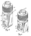
- Figure 2 is a perspective view of sensor extension 14 showing sensor coupling face 60 having a recessed sensor interface 62 formed therein.
- An opposing face 64 is positioned opposite sensor coupling face 60 and, in one embodiment, also includes a recessed sensor interface (not shown) similar to interface 62 for receiving a second pressure.
- the sensor is located in sensor extension 14 and is directly exposed to process fluid.
- the sensor is isolated from the process fluid by an isolation diaphragm.
- the sensor is spaced apart from the recessed sensor interface 62, for example in transmitter body 12, and is coupled to the process fluid by a coupling such as a small oil tube which transmits pressure.
- interface 62 may receive process fluid, either static or flowing fluid, therethrough.
- transmitter body 12 can be moved (i.e. rotated) between positions 66A and 66B relative to flange interfaces 16A and 16B. Movement beyond positions 68A and 68B is blocked by bolts 36 which contact sides of sensor extension 14.
- FIG 3 is a perspective view showing transmitter body 10 coupled to elongated sensor extension 70 in accordance with another embodiment.
- Elongated sensor extension 70 is shown in Figure 4 in a perspective view in greater detail and is similar to sensor extension 14.
- Sensor extension 70 includes elongated mid portion 72 including a bolt hole 74 formed therethrough.
- Bolt hole 74 is adapted to receive bolts 36 therethrough. This allows transmitter 10 to be positioned at an angle of 90° relative to the process face 76A and 76B of flange interfaces 16A and 16B.
- elongated sensor extension 70 may be rotated between positions 66A and 66B. For example, this may be between 80° and 100°.
- Figure 5 shows this 90° orientation of transmitter 10 in a perspective view.
- Figure 5 shows an embodiment in which vent valves 40A and 40B are positioned on top face 78A and 78B of flange interfaces 16A and 16B, respectively.
- One of the bolts 36 extends through bolt hole 74 in elongated sensor extension 70.
- Note the elongated sensor extension 70 provides a greater overall height when comparing the embodiment of Figure 3 with that of Figure 1.
- the embodiment of Figure 1 using sensor extension 14 cannot be rotated to the 90° position of Figure 5.
- FIG. 6 is an exploded perspective view showing transmitter 10 including an elongated sensor extension 70.
- flange interfaces 16A and 16B are coupled to process couplings 52A and 52B at process connections 80A and 80B, respectively.
- Vent valves 40A and 40B are received in vent valve opening 81A and opening 81B.
- Bolts 54 screw into flange interfaces 16A and 16B and O-ring 84 seats in O-ring seat 86 and secures process couplings 52A and 52B to interfaces 16A and 16B.
- O-rings 88 seat in O-ring seats 90 of elongated sensor extension 70 and in O-ring seats 92 of flange interfaces 16A and 16B.
- O-rings 84 and 88 should be made of any appropriate elastomeric material. Preferably, the material should be resistant to corrosion from the process fluid.
- FIG. 7 is a bottom plan view of flange interface 16A.
- a process connection 100 is shown which is surrounded by recess 102.
- Recess 102 is appropriate for receiving O-ring 84 (shown in Figure 6) therein.
- Process connection 100 is positioned to align with process connection 80 shown in Figure 6.
- Flange interface 16A also includes threaded bolt holes 104 which are positioned to align with bolt holes 106 shown in Figure 6.
- Bolts 54 are received through holes 106 and may be screwed into threaded bolt holes 104 such that flange interfaces 16A and 16B are coupled to manifold 50.
- Figure 8 is a cross sectional view of flange interface 16A taken along the line labeled 8--8 in Figure 7.
- Figure 8 shows threaded bolt holes 104.
- Figure 8 also shows bolt holes 106 for receiving bolts 36 therethrough.
- Process connection 100 may be threaded as shown in Figure 8 if desired.
- Process fluid is conveyed from impulse piping 52A and 52B through process connections 80 of manifold 50 and to process connections 100 of flange interfaces 16A and 16B.
- the process fluid is then applied to sensor interface 62 which, as explained above, could be an isolation diaphragm, through process connection 81A and 81B. It will be understood that a single process connection can be applied to one side of the sensor extension. Additionally, it is possible to provide flow through the sensor extension using the two paths described above whereby a sensor may be continuously exposed to circulating process fluid such that other types of measurements may be obtained, for example pH or temperature.
- FIG. 9 is a electrical schematic diagram of transmitter 10 coupled to process control loop wiring 28.
- Transmitter 10 couples to control loop wiring 28 at transmitter terminals 150.
- Transmitter 10 includes input/output circuitry 152, microprocessor 154, compensation circuitry 156 and sensor 158.
- Sensor 158 couples to compensation circuitry 156 through amplifier 160 and analog to digital conversion circuitry 162.
- the output of compensation circuitry couples to microprocessor 154 which is also connected to system clock 164 and memory 166.
- sensor 158 senses a process variable such as pressure, temperature, etc. The sensed process variable is amplified by amplifier 160 and digitized by analog to digital conversion circuitry 162.
- Compensation circuitry 156 operates to preprocess the process variable, for example compensating for errors in the process variable or converting the process variable into another variable, such as differential pressure into mass flow.
- the compensated process variable is provided to microprocessor 154 which operates in accordance with instructions stored in memory 166 and at a rate determined by system clock 164.
- Input/output circuitry 152 couples to control loop wiring 28 and allows microprocessor 154 to transmit information on loop wiring 28. Loop wiring 28 carries current I which is used by input/output circuitry 152 to provide a power output which issued to completely power transmitter 10. Additionally, microprocessor 154 is capable of receiving instructions over loop wiring 128 through input/output circuitry 152.
- FIG 10 is a side elevated plan view of transmitter 10 coupled to flange interfaces 180A and 180B in accordance with another embodiment.
- Transmitter 10 is shown with sensor extension 70, however sensor extension 14 of Figure 2 may also be used.
- Interfaces 180A and 180B include upper keys 182A and 182B and lower keys 184A and 184B, respectively.
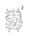
- Figure 11 is a bottom plan view showing flange interfaces 180A and 180B and sensor extension 70.
- Flange interfaces 180A and 180B carry process connections 190 and bolt holes 192.
- Sensor extension 70 is secured between keys 182A and 182B on one side of the sensor interface (not shown in Figures 10 and 11) and lower keys 184A and 184B on the other side of the sensor interface. This provides additional stability and prevents rotation of sensor extension 70 and transmitter 10 about the sensor interface held between flange interfaces 180A and 180B.
- transmitter 10 may be rotated 90° such that it is secured between keys 182A and 184A on one side and keys 182B and 184B on the other side.
- FIG 12 is a front elevated plan view and Figure 13 is a side elevated plan view of transmitter 10 coupled to flange interfaces 200A and 200B in accordance with another embodiment.
- Transmitter 10 is shown with sensor extension 70 secured between flange interfaces 200A and 200B using bolts 202 which are secured by nuts 210.
- Interfaces 200A and 200B include extensions 206 which contain bolt holes (not shown) extending therethrough. These bolt holes receive bolt 208 which extends through bolt hole 74 of sensor extension 70 and is secured by nut 212 shown in Figure 13. This third bolt 208 secures transmitter 10 in the upright position shown in Figures 12 and 13 and prevents rotation of transmitter 10 relative to interfaces 200A and 200B.
- a vent valve 216 may also be included in this embodiment.
- Figure 14 is a cut away view in accordance with another embodiment of manifold 222 showing set bolt 224 which secures sensor extension 14 to unitary manifold 222.
- Manifold 222 includes integral interface flanges 226A and 226B. As shown in the cut away view of flange 226A, a process passageway 228 is formed therethrough which couples to process piping 52A through set bolt notch 237. Set bolt notch 237 couples through process fluid entry hole 230 into piping passageway 234. Threaded passageway 232 of piping passageway 234 couples to process fluid entry hole 230 and vent 250 which includes vent stem 252.
- Set bolt 224 includes pressure plate 236.
- set bolt 224 is tightened to securely couple process fluid to process connection 62 through passageway 234 and to secure sensor extension 14 to manifold 222.
- O-rings 238 seat against flange 239 and threaded passageway 241.
- Pressure plate 236 seats against O-ring 88 at O-ring seat 240 providing a fluidic seal therebetween.
- the embodiment of Figure 14 has a reduced number of seals and cavities, and a single attachment bolt. This embodiment reduces the number of connections that must be sealed by O-rings and bolts. This reduces the chance of process fluid leakage and the likelihood of human error. Additionally, fabrication costs are reduced because there are fewer precision machined parts.
- Any technique for coupling the unitary manifold to the sensor extension may be employed.
- the present invention has a number of advantages.
- the invention allows for a reduced size in the overall transmitter and coupling apparatus used to couple to the process fluid.
- the reduced size allows transmitters to be used in small spaces and reduces the amount of material needed to manufacture transmitters.
- the flange interfaces are formed of 316 stainless steel and are resistant to corrosion from the process fluid. Other factors used in determining what materials should be used include the temperature range, expansion coefficients and ease of manufacturability of the material. Because of the reduced size, the various flanges and couplings are also easier to seal than larger sized elements.
- the transmitter may be easily rotated between zero and 90° relative to the process connection.
- the reduced size also allows for reduced overall weight making shipping and transportation of the devices more practical.
- memory 155 along with various combinations of sensor 158, amplifier 160, analog to digital conversion circuitry 162 and compensation circuitry 156 may reside in the sensor extension.
- sensor extensions for a specific task may be connected to a generic transmitter body.
- the interface flanges provide standard DIN spacing of 5,4 cm (2 1/8") and 1/4 NPT.
- Various embodiments of the present invention include placement of the various orifices and openings and any desired configuration using any appropriate internal passageway system.
- the various pieces may be fit together using techniques other than those specifically disclosed herein and all such techniques are considered to be within the scope of the present invention.
- attachment mechanisms other than the bolts and screws specifically set forth may be used.
- a single interface flange may be used in embodiments where only a single process connection is required such as, absolute pressure or temperature measurement.
- the interface flanges may be used with other sensor and transmitter configurations and are not limited to the specific sensor extension and transmitter body set forth herein. Any or all of the pieces may be formed individually or integral with each other.
- the sensor and/or sensor extension could be a part of the interface flange and/or manifold.
- the concepts set forth herein may be applied to more than two process connections.
Landscapes
- Physics & Mathematics (AREA)
- General Physics & Mathematics (AREA)
- Measuring Fluid Pressure (AREA)
- Arrangements For Transmission Of Measured Signals (AREA)
Description
Claims (13)
- A transmitter (10) of the type used in the process control industry for sensing a process variable of a process fluid, the transmitter (10) comprising:a transmitter body (12) having a sensor coupling (30);a sensor extension (14;70) coupled to the sensor coupling (30), the sensor extension (14;70) having a sensor coupling face (60) and an opposing face opposite (64) the sensor coupling face (60);a first flange interface (16A;180A;200A;226A) having a process face (76A) which connects to a process connection (80A) and a sensor coupling face (60) which mates with the sensor, the first flange interface (16A;180A;200A;226A) including a passageway (100;228) which couples the process fluid to the sensor coupling face (60);a second flange interface (16B;180B;200B;226B) positioned adjacent the opposing face (64) of the sensor extension (14;70) whereby the sensor extension is positioned between the first and second flange interfaces (16A,16B;180A,180B;200A,200B;226A,226B); andcoupling means (36,38;186,188;202,208,210,212;224,237) for coupling the first flange interface (16A;180A;200A;226A) to the second flange interface (16B;180B;200B;226B) whereby the sensor extension (14;70) is held therebetween and completely secured between the first and second flange interfaces (16A,16B;180A,180B;200A,200B;226A,226B) by force applied by the coupling means (36,38,186,188;202,208,290,242;224,237), the sensor extension (14;70) selectively positionable at a plurality of angles relative to the process face (76).
- A flange for coupling to a transmitter (10) of the type used to sense a process variable of a process fluid having a transmitter body (12) and a sensor extension (14;70) coupled to the sensor coupling (30), the sensor extension (14;70) having a sensor coupling face (60) and an opposing face (64) opposite the sensor coupling face (60), the transmitter flange comprising:a first flange interface (16A;180A) having a process face (76A) which connects to a process connection (80A) and a sensor coupling face (60) which mates with the sensor, the first flange interface (16A;180A) including a passageway (100) which couples the process fluid to the sensor coupling face (60);a second flange interface (16B;180B) positioned adjacent the opposing face (64) of the sensor extension (14;70) whereby the sensor extension (14;70) is positioned between the first and second flange interfaces (16A;16B;180A,180B); andcoupling means (36,38) for coupling the first flange interface (16A;180A) to the sensor extension second flange interface (16B;180B) whereby the sensor extension (14;70) is held therebetween and completely secured between the first and second flange interfaces (16A,16B;180A,180B) by force applied by the coupling means (36,38), the sensor extension (14;70) selectively positionable at a plurality of angles relative to the process face (76).
- The transmitter (10) of claims 1 or 2 wherein the sensor extension (14;70) includes features on the sensor coupling face (60) and the opposing face (64) and the first flange interface (16A;180A) includes features which conform to sensor coupling face (60) and the second flange interface (16B;180B) includes features which conform to the opposing face (64), the features provided to enhance coupling of the sensor extension (14;70) to the first and second flange interfaces (16A,16B,180A,180B).
- The transmitter (10) of any of the preceding claims wherein the second flange interface (16B;180B;200B;226B) includes a process face (76B) and a passageway extending between the process face (76B) and a face adjacent the opposing face (64) of the sensor extension (14;70).
- The transmitter (10) of any of the preceding claims including first and second vent plugs (40A,40B;250) in the respective first and second flange interfaces (16A,76B;180A,180B;200A,200B;226A,226B).
- The transmitter (10) of any of the preceding claims wherein the coupling means comprises at least two bolts (36;186;202,208;224) positioned on opposing sides of the sensor extension (14;70).
- The transmitter (10) of any of the preceding claims wherein the sensor extension (14;70) is selectively continuously positionable at an angle relative to the process face (76) of between less than about 80° and more than about 100°.
- The transmitter (10) of any of the preceding claims wherein at least one flange interface (180A,180B) includes a key (182,184) adapted to receive the sensor extension (14;70) therein to prevent rotation of the sensor extension (14;70) relative to the first and second flange interfaces (180A,180B).
- The transmitter (10) of claim 8 wherein the key (182,184) maintains the sensor extension (14;70) at an angle of about 90° relative to the process face (76).
- The transmitter (10) of claim 6 wherein the sensor extension (14;70) includes a bolt hole (74) for receiving a bolt (36;208) therethrough.
- The transmitter (10) of claim 10 wherein the sensor extension (14;70) is positioned at an angle of about 90° relative to the process face (76) and the bolt hole (74) receives a third bolt (208) therethrough
- The transmitter (10) of claim 10 wherein the sensor extension (14;70) is positioned generally parallel with the process interface (76) and at least one flange interface (180A,180B) includes a key (182, 184) which maintains the sensor extension (14; 70) in position relative to the process interface (76).
- The transmitter (10) of any of the preceding claims wherein the first and second flange interfaces (226A, 226B) are part of a unitary manifold (222).
Applications Claiming Priority (3)
| Application Number | Priority Date | Filing Date | Title |
|---|---|---|---|
| US661302 | 1996-06-13 | ||
| US08/661,302 US5668322A (en) | 1996-06-13 | 1996-06-13 | Apparatus for coupling a transmitter to process fluid having a sensor extension selectively positionable at a plurality of angles |
| PCT/US1997/009334 WO1997047954A1 (en) | 1996-06-13 | 1997-05-21 | Apparatus for coupling a transmitter to process fluid |
Publications (3)
| Publication Number | Publication Date |
|---|---|
| EP0843810A1 EP0843810A1 (en) | 1998-05-27 |
| EP0843810B1 true EP0843810B1 (en) | 2003-11-26 |
| EP0843810B2 EP0843810B2 (en) | 2007-12-05 |
Family
ID=24653038
Family Applications (1)
| Application Number | Title | Priority Date | Filing Date |
|---|---|---|---|
| EP97927876A Expired - Lifetime EP0843810B2 (en) | 1996-06-13 | 1997-05-21 | Apparatus for coupling a transmitter to process fluid |
Country Status (7)
| Country | Link |
|---|---|
| US (2) | US5668322A (en) |
| EP (1) | EP0843810B2 (en) |
| CN (1) | CN1116598C (en) |
| CA (1) | CA2228304A1 (en) |
| DE (1) | DE69726383T3 (en) |
| MX (1) | MX9800819A (en) |
| WO (1) | WO1997047954A1 (en) |
Cited By (1)
| Publication number | Priority date | Publication date | Assignee | Title |
|---|---|---|---|---|
| DE102008054991A1 (en) | 2008-12-19 | 2010-06-24 | Endress + Hauser Gmbh + Co. Kg | Differential |
Families Citing this family (80)
| Publication number | Priority date | Publication date | Assignee | Title |
|---|---|---|---|---|
| US5693887A (en) | 1995-10-03 | 1997-12-02 | Nt International, Inc. | Pressure sensor module having non-contaminating body and isolation member |
| USRE38557E1 (en) | 1995-10-03 | 2004-07-20 | Nt International, Inc. | Non-contaminating pressure transducer module |
| US8290721B2 (en) | 1996-03-28 | 2012-10-16 | Rosemount Inc. | Flow measurement diagnostics |
| WO1999028718A1 (en) * | 1997-12-02 | 1999-06-10 | Fluoroware, Inc. | Fluid monitoring device |
| WO2000008417A2 (en) * | 1998-07-22 | 2000-02-17 | Ssi Technologies, Inc. | Sensor assembly with floating connection |
| US6176262B1 (en) * | 1998-09-14 | 2001-01-23 | Spencer M. Nimberger | Two-piece manifold system for pressure sensing transmitters |
| DE19921172C1 (en) * | 1999-05-07 | 2000-11-16 | Martin Hess | Pressure transmitter installation on a process line of a process plant |
| US6571132B1 (en) | 1999-09-28 | 2003-05-27 | Rosemount Inc. | Component type adaptation in a transducer assembly |
| US6765968B1 (en) | 1999-09-28 | 2004-07-20 | Rosemount Inc. | Process transmitter with local databus |
| US7134354B2 (en) | 1999-09-28 | 2006-11-14 | Rosemount Inc. | Display for process transmitter |
| WO2001024594A2 (en) | 1999-09-28 | 2001-04-05 | Rosemount Inc. | Environmentally sealed instrument loop adapter |
| US6487912B1 (en) | 1999-09-28 | 2002-12-03 | Rosemount Inc. | Preinstallation of a pressure sensor module |
| US6484107B1 (en) | 1999-09-28 | 2002-11-19 | Rosemount Inc. | Selectable on-off logic modes for a sensor module |
| US6510740B1 (en) | 1999-09-28 | 2003-01-28 | Rosemount Inc. | Thermal management in a pressure transmitter |
| US6546805B2 (en) | 2000-03-07 | 2003-04-15 | Rosemount Inc. | Process fluid transmitter with an environmentally sealed service block |
| USD439178S1 (en) | 2000-03-21 | 2001-03-20 | Rosemount Inc. | Pressure transmitter with dual inlet base and single compartment housing |
| USD439181S1 (en) | 2000-03-21 | 2001-03-20 | Rosemount Inc. | Pressure transmitter with dual inlet base and dual compartment housing |
| USD439177S1 (en) | 2000-03-21 | 2001-03-20 | Rosemount Inc. | Pressure transmitter with single inlet base and economy housing |
| USD439179S1 (en) | 2000-03-21 | 2001-03-20 | Rosemount Inc. | Pressure transmitter with single inlet base and dual compartment housing |
| USD441672S1 (en) | 2000-03-21 | 2001-05-08 | Rosemount Inc. | Pressure transmitter with dual inlet base and economy housing |
| USD439180S1 (en) | 2000-03-21 | 2001-03-20 | Rosemount Inc. | Pressure transmitter with single inlet base and single compartment housing |
| US6662662B1 (en) | 2000-05-04 | 2003-12-16 | Rosemount, Inc. | Pressure transmitter with improved isolator system |
| US6504489B1 (en) | 2000-05-15 | 2003-01-07 | Rosemount Inc. | Process control transmitter having an externally accessible DC circuit common |
| US6550338B1 (en) | 2000-07-07 | 2003-04-22 | Ardishir Rashidi | Pressure sensing device |
| US6480131B1 (en) | 2000-08-10 | 2002-11-12 | Rosemount Inc. | Multiple die industrial process control transmitter |
| ITMI20011045A1 (en) * | 2001-05-18 | 2002-11-18 | Abb Ricerca Spa | PRESSURE TRANSMITTERS PARTICULARLY FOR THE DETECTION OF A PHYSICAL VARIABLE RELATED TO A PROCESS FLUID |
| US6516672B2 (en) | 2001-05-21 | 2003-02-11 | Rosemount Inc. | Sigma-delta analog to digital converter for capacitive pressure sensor and process transmitter |
| DE10133065A1 (en) * | 2001-07-07 | 2003-01-16 | Endress & Hauser Gmbh & Co Kg | Pressure measurement transducer comprising a pressure measurement cell tensioned between sealing and positioning flanges, with the flanges having flexible connections suitable for connection to valves or process connections |
| US6684711B2 (en) | 2001-08-23 | 2004-02-03 | Rosemount Inc. | Three-phase excitation circuit for compensated capacitor industrial process control transmitters |
| ITMI20012012A1 (en) * | 2001-09-27 | 2003-03-27 | Abb Service Srl | DIFFERENTIAL PRESSURE TRANSMITTER WITH SIMPLIFIED STRUCTURE |
| USD472831S1 (en) | 2001-10-11 | 2003-04-08 | Rosemount Inc. | Single inlet base pressure instrument |
| USD471829S1 (en) | 2001-10-11 | 2003-03-18 | Rosemount Inc. | Dual inlet base pressure instrument |
| US6675655B2 (en) | 2002-03-21 | 2004-01-13 | Rosemount Inc. | Pressure transmitter with process coupling |
| US7109883B2 (en) | 2002-09-06 | 2006-09-19 | Rosemount Inc. | Low power physical layer for a bus in an industrial transmitter |
| US7773715B2 (en) | 2002-09-06 | 2010-08-10 | Rosemount Inc. | Two wire transmitter with isolated can output |
| US7523667B2 (en) | 2003-12-23 | 2009-04-28 | Rosemount Inc. | Diagnostics of impulse piping in an industrial process |
| US7464721B2 (en) * | 2004-06-14 | 2008-12-16 | Rosemount Inc. | Process equipment validation |
| US7373831B2 (en) * | 2004-06-25 | 2008-05-20 | Rosemount Inc. | High temperature pressure transmitter assembly |
| US7258021B2 (en) * | 2004-06-25 | 2007-08-21 | Rosemount Inc. | Process transmitter isolation assembly |
| US7036381B2 (en) * | 2004-06-25 | 2006-05-02 | Rosemount Inc. | High temperature pressure transmitter assembly |
| US7334484B2 (en) * | 2005-05-27 | 2008-02-26 | Rosemount Inc. | Line pressure measurement using differential pressure sensor |
| US20070068225A1 (en) | 2005-09-29 | 2007-03-29 | Brown Gregory C | Leak detector for process valve |
| US7379792B2 (en) * | 2005-09-29 | 2008-05-27 | Rosemount Inc. | Pressure transmitter with acoustic pressure sensor |
| US7415886B2 (en) | 2005-12-20 | 2008-08-26 | Rosemount Inc. | Pressure sensor with deflectable diaphragm |
| US7525419B2 (en) | 2006-01-30 | 2009-04-28 | Rosemount Inc. | Transmitter with removable local operator interface |
| ITMI20060152A1 (en) * | 2006-01-30 | 2007-07-31 | Abb Service Srl | TRANSMITTER FOR THE CONTROL OF INDUSTRIAL PROCESSES |
| US8788070B2 (en) | 2006-09-26 | 2014-07-22 | Rosemount Inc. | Automatic field device service adviser |
| US8898036B2 (en) | 2007-08-06 | 2014-11-25 | Rosemount Inc. | Process variable transmitter with acceleration sensor |
| US7497123B1 (en) | 2007-12-18 | 2009-03-03 | Rosemount Inc. | Direct mount for pressure transmitter with thermal management |
| CN100535622C (en) * | 2008-03-10 | 2009-09-02 | 李岩峰 | Variable scale differential pressure transmitter |
| JP5677947B2 (en) * | 2008-06-18 | 2015-02-25 | ローズマウント インコーポレイテッド | Detection of flood in distillation column |
| US7954383B2 (en) * | 2008-12-03 | 2011-06-07 | Rosemount Inc. | Method and apparatus for pressure measurement using fill tube |
| US7870791B2 (en) | 2008-12-03 | 2011-01-18 | Rosemount Inc. | Method and apparatus for pressure measurement using quartz crystal |
| US8327713B2 (en) | 2008-12-03 | 2012-12-11 | Rosemount Inc. | Method and apparatus for pressure measurement using magnetic property |
| US8015882B2 (en) * | 2009-06-04 | 2011-09-13 | Rosemount Inc. | Industrial process control pressure transmitter and flange coupling |
| CA2721884A1 (en) * | 2009-11-19 | 2011-05-19 | Peter B. Hutton | Purge manifold |
| US8334788B2 (en) | 2010-03-04 | 2012-12-18 | Rosemount Inc. | Process variable transmitter with display |
| US8429978B2 (en) | 2010-03-30 | 2013-04-30 | Rosemount Inc. | Resonant frequency based pressure sensor |
| US8234927B2 (en) | 2010-06-08 | 2012-08-07 | Rosemount Inc. | Differential pressure sensor with line pressure measurement |
| US8132464B2 (en) | 2010-07-12 | 2012-03-13 | Rosemount Inc. | Differential pressure transmitter with complimentary dual absolute pressure sensors |
| US9207670B2 (en) | 2011-03-21 | 2015-12-08 | Rosemount Inc. | Degrading sensor detection implemented within a transmitter |
| US9010191B2 (en) | 2011-12-22 | 2015-04-21 | Rosemount Inc. | Pressure sensor module for sub-sea applications |
| EP2626148B1 (en) * | 2012-02-13 | 2019-03-27 | Alfa Laval Corporate AB | Monitoring of systems for internal cleaning of containers |
| WO2013134232A2 (en) | 2012-03-06 | 2013-09-12 | Rosemount, Inc. | Remote seal pressure measurement system for subsea use |
| US8752433B2 (en) | 2012-06-19 | 2014-06-17 | Rosemount Inc. | Differential pressure transmitter with pressure sensor |
| US9052240B2 (en) | 2012-06-29 | 2015-06-09 | Rosemount Inc. | Industrial process temperature transmitter with sensor stress diagnostics |
| US9157824B2 (en) * | 2012-09-28 | 2015-10-13 | Rosemount Inc. | High pressure fluid coupling |
| US9602122B2 (en) | 2012-09-28 | 2017-03-21 | Rosemount Inc. | Process variable measurement noise diagnostic |
| US9568136B2 (en) | 2013-03-14 | 2017-02-14 | Rosemount, Inc. | Separately replaceable seal systems for use with a pressure transmitter |
| US9442031B2 (en) | 2013-06-28 | 2016-09-13 | Rosemount Inc. | High integrity process fluid pressure probe |
| EP3598097B8 (en) * | 2013-07-19 | 2023-10-11 | Rosemount, Inc. | Pressure transmitter having an isolation assembly with a two-piece isolator plug |
| US9234776B2 (en) | 2013-09-26 | 2016-01-12 | Rosemount Inc. | Multivariable process fluid transmitter for high pressure applications |
| US9459170B2 (en) | 2013-09-26 | 2016-10-04 | Rosemount Inc. | Process fluid pressure sensing assembly for pressure transmitters subjected to high working pressure |
| DE102013113728A1 (en) * | 2013-12-09 | 2015-06-11 | Bürkert SAS | Control head of a fluid-controlling or measuring device, fluid-controlling or measuring device and method for producing a control head |
| US9479201B2 (en) * | 2014-03-26 | 2016-10-25 | Rosemount Inc. | Process variable transmitter with removable terminal block |
| US9638600B2 (en) | 2014-09-30 | 2017-05-02 | Rosemount Inc. | Electrical interconnect for pressure sensor in a process variable transmitter |
| US20160102788A1 (en) * | 2014-10-08 | 2016-04-14 | General Electric Company | Transmitter mounting system and method of mounting |
| US10081039B2 (en) * | 2014-12-18 | 2018-09-25 | Dieterich Standard, Inc. | Rodable pressure coupling |
| CN105953974A (en) * | 2016-06-30 | 2016-09-21 | 扬中市众成管路配件有限公司 | Pressure transmitter |
| DE102016117989A1 (en) | 2016-09-23 | 2018-03-29 | Endress + Hauser Gmbh + Co. Kg | Flange set for a differential pressure sensor |
Family Cites Families (78)
| Publication number | Priority date | Publication date | Assignee | Title |
|---|---|---|---|---|
| US34610A (en) * | 1862-03-04 | Improved clothes-wringer | ||
| US1272344A (en) * | 1913-01-10 | 1918-07-09 | Foxboro Co | Measuring instrument. |
| US1797591A (en) * | 1927-05-23 | 1931-03-24 | Wayne Pump Co | Battery of valves |
| US2355270A (en) * | 1941-11-12 | 1944-08-08 | Julian A Campbell | Boiler feed water control |
| DE863396C (en) * | 1943-08-23 | 1953-01-19 | W App Nfabriek N V Automatic S | Fluid connection and distributor body for a through-flow fluid heater |
| US2804879A (en) * | 1953-07-27 | 1957-09-03 | Frank R Hanson | Water distributor |
| US2949130A (en) * | 1956-06-21 | 1960-08-16 | Bell Brothers Domestic Ltd | Mixing valve |
| US2943640A (en) * | 1956-09-11 | 1960-07-05 | Gulf Oil Corp | Manifold for dual zone well |
| US2871881A (en) * | 1957-01-28 | 1959-02-03 | John E Hewson | Valve manifold |
| FR1206824A (en) * | 1957-05-18 | 1960-02-11 | Ct D Etude Et De Diffusion | Installation for measuring the consistency of a paste |
| US3228665A (en) * | 1963-10-04 | 1966-01-11 | Melvin C Dolan | Water purification device |
| FR1381887A (en) * | 1964-02-06 | 1964-12-14 | Process for the purification of industrial waste water by separating it into a liquid part and a muddy part containing impurities | |
| FR1467957A (en) * | 1965-12-23 | 1967-02-03 | Semi-automatic dispenser for liquid or pasty products | |
| US3450157A (en) * | 1967-07-31 | 1969-06-17 | John E Hewson | Valve manifold |
| GB1206824A (en) * | 1968-01-22 | 1970-09-30 | Smolensky Gnii Teploenergetich | Device arranged between a pressure-measuring instrument and a substance whose pressure is to be measured |
| FR1572814A (en) * | 1968-07-05 | 1969-06-27 | ||
| US3653405A (en) * | 1970-01-05 | 1972-04-04 | Int Harvester Co | Fluid line coupler |
| US3628566A (en) * | 1970-02-02 | 1971-12-21 | Clifford C Carse | Multiple fluid control device |
| US3633618A (en) * | 1970-02-26 | 1972-01-11 | Joseph J Blackmore | Valved manifold for gauging a plurality of fluid pressures |
| AT317639B (en) * | 1971-01-19 | 1974-09-10 | Messer Griesheim Gmbh | Line connection to gas burners such as cutting torches, scarfing burners or preheating burners |
| US3817283A (en) * | 1971-04-07 | 1974-06-18 | J Hewson | Differential pressure transducer process mounting support |
| US3768511A (en) * | 1971-11-15 | 1973-10-30 | S Bias | Control device |
| US3974998A (en) * | 1972-07-28 | 1976-08-17 | Crown Cork & Seal Company, Inc. | Spray coating apparatus |
| CA977650A (en) * | 1973-07-25 | 1975-11-11 | Almo Manifold And Tool Company | Hydraulic manifold system |
| US3894559A (en) * | 1974-03-28 | 1975-07-15 | Leland Q Depuy | Manifold valve |
| GB1467957A (en) * | 1974-05-20 | 1977-03-23 | Hoke Inc | Mounting adaptor |
| DE2424839A1 (en) * | 1974-05-22 | 1975-12-04 | Hoke Inc | Measuring instrument attaching adaptor block - incorporates suitable fixing holes and flow channels |
| US4092865A (en) * | 1976-06-24 | 1978-06-06 | Gould Inc. | Fluid-test apparatus |
| GB1572814A (en) * | 1977-04-07 | 1980-08-06 | Robertshaw Skil Ltd | Pressure sensing |
| US4193420A (en) * | 1978-03-02 | 1980-03-18 | Hewson John E | Differential pressure transducer process mounting support and manifold |
| US4182362A (en) * | 1978-03-09 | 1980-01-08 | Anderson, Greenwood & Co. | Differential transmitter and manifold mounting |
| US4215721A (en) * | 1978-12-11 | 1980-08-05 | Poly-Glas Systems | Modular multiple-fluid component selection and delivery system |
| IT1129054B (en) * | 1980-01-08 | 1986-06-04 | Fiat Ricerche | FLOW RATE REGULATOR FOR HYDRAULIC CIRCUITS |
| US4319492A (en) * | 1980-01-23 | 1982-03-16 | Anderson, Greenwood & Co. | Pressure transmitter manifold |
| JPS56129659A (en) * | 1980-03-14 | 1981-10-09 | Kaname Wakasugi | Desalted sand manufacture and device therefor |
| GB2086535A (en) * | 1980-10-16 | 1982-05-12 | Marown Engineering Ltd | Improvements in the manifolding of differential pressure transmitters |
| US4466290A (en) * | 1981-11-27 | 1984-08-21 | Rosemount Inc. | Apparatus for conveying fluid pressures to a differential pressure transducer |
| US4429711A (en) * | 1982-03-08 | 1984-02-07 | Anderson, Greenwood & Co. | Multivalve manifold interlock and control system |
| US4582089A (en) * | 1984-10-31 | 1986-04-15 | General Screw Products Company | Valve manifold having a removable flange |
| US4672995A (en) * | 1984-12-28 | 1987-06-16 | Anderson-Greenwood Usa, Inc. | Redundant pilot valve control system |
| US4602657A (en) * | 1985-02-11 | 1986-07-29 | Anderson-Greenwood & Co. | Valve manifold for a differential pressure transmitter |
| US4655074A (en) * | 1985-08-12 | 1987-04-07 | The Babcock & Wilcox Company | Self-zeroing pressure transmitter with automatic pressure manifold |
| USD296995S (en) | 1985-09-27 | 1988-08-02 | Rosemount Inc. | Pressure transmitter housing |
| USD297315S (en) | 1985-12-16 | 1988-08-23 | Rosemount Inc. | Compact differential pressure transmitter |
| CA1240584A (en) * | 1986-01-28 | 1988-08-16 | Edward R. Coleman | Valve manifold |
| US5117867A (en) * | 1986-06-06 | 1992-06-02 | Adams Don L | Manifold for a differential pressure transmitter |
| US4738276A (en) * | 1986-06-06 | 1988-04-19 | Adams Donald L | Modular differential pressure transmitter/manifold for a fluid conveying pipeline |
| US4865360A (en) * | 1986-06-06 | 1989-09-12 | Adams Donald L | Modular differential pressure transmitter/manifold for a fluid conveying pipeline |
| US4977917A (en) * | 1986-06-06 | 1990-12-18 | Adams Don L | Modular differential pressure transmitter/manifold for a fluid conveying pipeline |
| JPH0695055B2 (en) * | 1986-07-18 | 1994-11-24 | 山武ハネウエル株式会社 | Remote seal type differential pressure / pressure transmitter |
| US4745810A (en) * | 1986-09-15 | 1988-05-24 | Rosemount Inc. | Flangeless transmitter coupling to a flange adapter union |
| US5209258A (en) * | 1987-03-02 | 1993-05-11 | Daniel Flow Products | Apparatus and method for minimizing pulsation-induced errors in differential pressure flow measuring devices |
| LU86802A1 (en) * | 1987-03-09 | 1987-08-12 | Ceodeux Sa | CONTROL UNIT FOR GAS UNDER PRESSURE |
| US4798089A (en) * | 1987-03-12 | 1989-01-17 | Rosemount Inc. | Isolator apparatus |
| US4833922A (en) * | 1987-06-01 | 1989-05-30 | Rosemount Inc. | Modular transmitter |
| IT1222940B (en) * | 1987-10-19 | 1990-09-12 | Dropsa Spa | MODULAR PROGRESSIVE HYDRAULIC DISTRIBUTOR FOR LUBRICATION SYSTEMS |
| US4828221A (en) * | 1987-11-06 | 1989-05-09 | Keystone International, Inc. | Valve assembly |
| USD318432S (en) | 1988-04-22 | 1991-07-23 | Rosemount Inc. | Pressure transmitter housing |
| USD317266S (en) | 1988-04-22 | 1991-06-04 | Rosemount Inc. | Pressure transmitter housing |
| US5036711A (en) * | 1989-09-05 | 1991-08-06 | Fred P. Good | Averaging pitot tube |
| US4993754A (en) * | 1989-09-29 | 1991-02-19 | Rosemount Inc. | Liquid level coplanar transmitter adapter |
| DE4004834C2 (en) * | 1990-02-16 | 1996-06-13 | Festo Kg | Valve assembly |
| JPH04116437A (en) * | 1990-09-07 | 1992-04-16 | Fuji Electric Co Ltd | Differential pressure measuring apparatus with flange |
| US5036884A (en) * | 1990-11-19 | 1991-08-06 | Keystone International Holdings Corp. | Mounting means for fluid pressure transmitters |
| US5094109A (en) * | 1990-12-06 | 1992-03-10 | Rosemount Inc. | Pressure transmitter with stress isolation depression |
| US5248167A (en) * | 1991-09-12 | 1993-09-28 | Rosemount Inc. | Interchangeable process connection resistant to installation errors |
| MY109053A (en) * | 1991-09-12 | 1996-11-30 | Rosemount Inc | Interchangeable process connection resistant to installation errors. |
| GB2260387B (en) * | 1991-09-14 | 1995-11-29 | Oliver Valves Ltd | Improvements in or relating to valves |
| GB2271164B (en) * | 1992-08-22 | 1994-09-21 | Oliver Valves Ltd | Valve assembly |
| US5339863A (en) * | 1992-12-18 | 1994-08-23 | Mid-America Power Drives Manufacturing & Distributing, Inc. | Port mounted implement selector |
| US5303733A (en) * | 1993-02-08 | 1994-04-19 | Robertshaw Controls Company | Pressure regulating unit for beverage dispensing system |
| US5277224A (en) * | 1993-03-02 | 1994-01-11 | Century Industries Inc. | Five valve manifold for use with a pressure sensing apparatus |
| US5449294A (en) * | 1993-03-26 | 1995-09-12 | Texas Instruments Incorporated | Multiple valve assembly and process |
| SG41962A1 (en) * | 1993-09-24 | 1997-08-15 | Rosemount Inc | Pressure transmitter isolation diaphragm |
| US5494071A (en) * | 1994-06-03 | 1996-02-27 | Keystone International Holdings Corp. | Mounting system for pressure transmitters |
| US5583294A (en) * | 1994-08-22 | 1996-12-10 | The Foxboro Company | Differential pressure transmitter having an integral flame arresting body and overrange diaphragm |
| US5762100A (en) * | 1995-10-23 | 1998-06-09 | Wilda; Douglas W. | Head for coplanar meter body transmitter |
| US5722457A (en) * | 1995-10-23 | 1998-03-03 | Wilda; Douglas W. | Integrated manifold for coplanar pressure transmitter |
-
1996
- 1996-06-13 US US08/661,302 patent/US5668322A/en not_active Expired - Lifetime
-
1997
- 1997-05-21 DE DE69726383T patent/DE69726383T3/en not_active Expired - Lifetime
- 1997-05-21 WO PCT/US1997/009334 patent/WO1997047954A1/en not_active Ceased
- 1997-05-21 CN CN97190703A patent/CN1116598C/en not_active Expired - Fee Related
- 1997-05-21 CA CA002228304A patent/CA2228304A1/en not_active Abandoned
- 1997-05-21 EP EP97927876A patent/EP0843810B2/en not_active Expired - Lifetime
- 1997-05-21 MX MX9800819A patent/MX9800819A/en not_active Application Discontinuation
- 1997-09-15 US US08/929,804 patent/US5920016A/en not_active Expired - Lifetime
Cited By (2)
| Publication number | Priority date | Publication date | Assignee | Title |
|---|---|---|---|---|
| DE102008054991A1 (en) | 2008-12-19 | 2010-06-24 | Endress + Hauser Gmbh + Co. Kg | Differential |
| US8726735B2 (en) | 2008-12-19 | 2014-05-20 | Endress + Hauser Gmbh + Co. Kg | Pressure difference measurement transmitter |
Also Published As
| Publication number | Publication date |
|---|---|
| CA2228304A1 (en) | 1997-12-18 |
| DE69726383D1 (en) | 2004-01-08 |
| DE69726383T3 (en) | 2008-06-19 |
| CN1116598C (en) | 2003-07-30 |
| CN1195400A (en) | 1998-10-07 |
| DE69726383T2 (en) | 2004-09-02 |
| US5920016A (en) | 1999-07-06 |
| EP0843810B2 (en) | 2007-12-05 |
| MX9800819A (en) | 1998-04-30 |
| US5668322A (en) | 1997-09-16 |
| WO1997047954A1 (en) | 1997-12-18 |
| EP0843810A1 (en) | 1998-05-27 |
Similar Documents
| Publication | Publication Date | Title |
|---|---|---|
| EP0843810B1 (en) | Apparatus for coupling a transmitter to process fluid | |
| MXPA98000819A (en) | Apparatus for coupling a transmitter to the fluid of proc | |
| US5988203A (en) | Two-piece manifold | |
| US6000427A (en) | Manifold for use with dual pressure sensor units | |
| EP0094429B1 (en) | Apparatus for conveying fluid pressures to a differential pressure transducer | |
| US5753820A (en) | Fluid pressure sensing unit incorporating diaphragm deflection sensing array | |
| EP2013601B1 (en) | Redundant mechanical and electronic remote seal system | |
| EP0323963B1 (en) | Flangeless transmitter coupling to a flange adapter union | |
| US4993754A (en) | Liquid level coplanar transmitter adapter | |
| US5725024A (en) | Manifold valve having controlled vent port integral with flange | |
| EP1328784B1 (en) | In-line pressure transmitter | |
| AU738140B2 (en) | Two-piece manifold | |
| US6079443A (en) | Instrument valve manifolds for use with pressure transmitters | |
| US7131336B2 (en) | Pressure transmitter installation in a process line of a process facility | |
| US6182701B1 (en) | Swivel-type static pressure bar adapter |
Legal Events
| Date | Code | Title | Description |
|---|---|---|---|
| PUAI | Public reference made under article 153(3) epc to a published international application that has entered the european phase |
Free format text: ORIGINAL CODE: 0009012 |
|
| AK | Designated contracting states |
Kind code of ref document: A1 Designated state(s): DE GB |
|
| 17P | Request for examination filed |
Effective date: 19980506 |
|
| 17Q | First examination report despatched |
Effective date: 20010521 |
|
| GRAG | Despatch of communication of intention to grant |
Free format text: ORIGINAL CODE: EPIDOS AGRA |
|
| GRAG | Despatch of communication of intention to grant |
Free format text: ORIGINAL CODE: EPIDOS AGRA |
|
| GRAG | Despatch of communication of intention to grant |
Free format text: ORIGINAL CODE: EPIDOS AGRA |
|
| GRAH | Despatch of communication of intention to grant a patent |
Free format text: ORIGINAL CODE: EPIDOS IGRA |
|
| GRAH | Despatch of communication of intention to grant a patent |
Free format text: ORIGINAL CODE: EPIDOS IGRA |
|
| GRAA | (expected) grant |
Free format text: ORIGINAL CODE: 0009210 |
|
| AK | Designated contracting states |
Kind code of ref document: B1 Designated state(s): DE GB |
|
| REG | Reference to a national code |
Ref country code: GB Ref legal event code: FG4D |
|
| REF | Corresponds to: |
Ref document number: 69726383 Country of ref document: DE Date of ref document: 20040108 Kind code of ref document: P |
|
| PGFP | Annual fee paid to national office [announced via postgrant information from national office to epo] |
Ref country code: GB Payment date: 20040602 Year of fee payment: 8 |
|
| PLBQ | Unpublished change to opponent data |
Free format text: ORIGINAL CODE: EPIDOS OPPO |
|
| PLBI | Opposition filed |
Free format text: ORIGINAL CODE: 0009260 |
|
| PLAX | Notice of opposition and request to file observation + time limit sent |
Free format text: ORIGINAL CODE: EPIDOSNOBS2 |
|
| 26 | Opposition filed |
Opponent name: ENDRESS + HAUSER GMBH + CO.KG Effective date: 20040816 |
|
| PLAX | Notice of opposition and request to file observation + time limit sent |
Free format text: ORIGINAL CODE: EPIDOSNOBS2 |
|
| PLBB | Reply of patent proprietor to notice(s) of opposition received |
Free format text: ORIGINAL CODE: EPIDOSNOBS3 |
|
| PG25 | Lapsed in a contracting state [announced via postgrant information from national office to epo] |
Ref country code: GB Free format text: LAPSE BECAUSE OF NON-PAYMENT OF DUE FEES Effective date: 20050521 |
|
| GBPC | Gb: european patent ceased through non-payment of renewal fee |
Effective date: 20050521 |
|
| PUAH | Patent maintained in amended form |
Free format text: ORIGINAL CODE: 0009272 |
|
| STAA | Information on the status of an ep patent application or granted ep patent |
Free format text: STATUS: PATENT MAINTAINED AS AMENDED |
|
| 27A | Patent maintained in amended form |
Effective date: 20071205 |
|
| AK | Designated contracting states |
Kind code of ref document: B2 Designated state(s): DE GB |
|
| PGFP | Annual fee paid to national office [announced via postgrant information from national office to epo] |
Ref country code: DE Payment date: 20130530 Year of fee payment: 17 |
|
| REG | Reference to a national code |
Ref country code: DE Ref legal event code: R119 Ref document number: 69726383 Country of ref document: DE |
|
| REG | Reference to a national code |
Ref country code: DE Ref legal event code: R119 Ref document number: 69726383 Country of ref document: DE Effective date: 20141202 |
|
| PG25 | Lapsed in a contracting state [announced via postgrant information from national office to epo] |
Ref country code: DE Free format text: LAPSE BECAUSE OF NON-PAYMENT OF DUE FEES Effective date: 20141202 |