EP0847105A1 - Borne de raccordement d'un conducteur à un appareillage électrique de type modulaire - Google Patents
Borne de raccordement d'un conducteur à un appareillage électrique de type modulaire Download PDFInfo
- Publication number
- EP0847105A1 EP0847105A1 EP96440102A EP96440102A EP0847105A1 EP 0847105 A1 EP0847105 A1 EP 0847105A1 EP 96440102 A EP96440102 A EP 96440102A EP 96440102 A EP96440102 A EP 96440102A EP 0847105 A1 EP0847105 A1 EP 0847105A1
- Authority
- EP
- European Patent Office
- Prior art keywords
- screw
- tooth
- shells
- conductor
- teeth
- Prior art date
- Legal status (The legal status is an assumption and is not a legal conclusion. Google has not performed a legal analysis and makes no representation as to the accuracy of the status listed.)
- Granted
Links
Images


Classifications
-
- H—ELECTRICITY
- H01—ELECTRIC ELEMENTS
- H01R—ELECTRICALLY-CONDUCTIVE CONNECTIONS; STRUCTURAL ASSOCIATIONS OF A PLURALITY OF MUTUALLY-INSULATED ELECTRICAL CONNECTING ELEMENTS; COUPLING DEVICES; CURRENT COLLECTORS
- H01R4/00—Electrically-conductive connections between two or more conductive members in direct contact, i.e. touching one another; Means for effecting or maintaining such contact; Electrically-conductive connections having two or more spaced connecting locations for conductors and using contact members penetrating insulation
- H01R4/28—Clamped connections, spring connections
- H01R4/30—Clamped connections, spring connections utilising a screw or nut clamping member
- H01R4/36—Conductive members located under tip of screw
- H01R4/363—Conductive members located under tip of screw with intermediate part between tip and conductive member
-
- H—ELECTRICITY
- H01—ELECTRIC ELEMENTS
- H01R—ELECTRICALLY-CONDUCTIVE CONNECTIONS; STRUCTURAL ASSOCIATIONS OF A PLURALITY OF MUTUALLY-INSULATED ELECTRICAL CONNECTING ELEMENTS; COUPLING DEVICES; CURRENT COLLECTORS
- H01R13/00—Details of coupling devices of the kinds covered by groups H01R12/70 or H01R24/00 - H01R33/00
- H01R13/40—Securing contact members in or to a base or case; Insulating of contact members
- H01R13/42—Securing in a demountable manner
-
- H—ELECTRICITY
- H01—ELECTRIC ELEMENTS
- H01R—ELECTRICALLY-CONDUCTIVE CONNECTIONS; STRUCTURAL ASSOCIATIONS OF A PLURALITY OF MUTUALLY-INSULATED ELECTRICAL CONNECTING ELEMENTS; COUPLING DEVICES; CURRENT COLLECTORS
- H01R4/00—Electrically-conductive connections between two or more conductive members in direct contact, i.e. touching one another; Means for effecting or maintaining such contact; Electrically-conductive connections having two or more spaced connecting locations for conductors and using contact members penetrating insulation
- H01R4/28—Clamped connections, spring connections
- H01R4/38—Clamped connections, spring connections utilising a clamping member acted on by screw or nut
-
- H—ELECTRICITY
- H01—ELECTRIC ELEMENTS
- H01R—ELECTRICALLY-CONDUCTIVE CONNECTIONS; STRUCTURAL ASSOCIATIONS OF A PLURALITY OF MUTUALLY-INSULATED ELECTRICAL CONNECTING ELEMENTS; COUPLING DEVICES; CURRENT COLLECTORS
- H01R13/00—Details of coupling devices of the kinds covered by groups H01R12/70 or H01R24/00 - H01R33/00
- H01R13/46—Bases; Cases
- H01R13/502—Bases; Cases composed of different pieces
Definitions
- connection terminal of a conductor to modular type electrical equipment, consisting of a housing formed by two assembled half-shells, or resulting from a cover / base assembly comprising a housing planned to accommodate said terminal.
- a connection terminal has a cage housing a cooperating contact plate with a screw provided for bringing said plate apart or apart of one of the walls of the cage, in order to fix by clamping or release by loosening said conductor.
- Modular electrical devices concerned by the invention generally have an even number of terminals used to connect to circuits in which they perform a function particular. These are, for example, circuit breakers, auxiliaries circuit breakers, contactors, etc.
- the problem posed and resolved by the present invention relates to the maintenance of the cages in the housings.
- the cages are in most cases arranged floating inside the housings provided in the boxes for welcome them.
- Said housings being made up of two half-shells, the housings are distributed in these half-shells, divided in two half-housings located opposite, separated by the plane of separation of the half-shells.
- the housing then remains joined during the tightening operation.
- the rotational movement imparted to the screw is not transmitted to the cage due to its attachment to the housing and, in combination with the anchoring of the teeth in the half-shells, contributes to ensuring an effective tightening of the conductor without deformation of the insulating housing.
- the object of the invention also consists in producing a terminal for connection which does not cause deformation of the case during the tightening operation, but without modifying the cage.
- the contact plate housed in the cage which includes means for anchoring to the housing of the electrical equipment.
- the torque exerted on the screw is transmitted to the half-shells so that they approach the level of their junction surfaces.
- the means for anchoring the contact plate have teeth protruding towards stops made in said half-shells, intended to become embedded in said abutments progressively the exercise of the tightening torque on the screw.
- the teeth are located on the edges of said contact pad oriented opposite the head of said screw, the tip of each tooth encrusting along an axis parallel to that of the screw, in the tightening direction axial of the latter.
- each contact pad has at least one tooth cooperating with a surface of a stop that is substantially perpendicular in shape to the axis of the screw and located on each of the half-shells forming the housing.
- the contact plate has a central body plane provided with two portions of ends perpendicular to said body, of which one is provided with lateral fins projecting from each side of said body central, one of the teeth being located on the end edge of the portion perpendicular without fin, offset to the side, the other tooth being located on the parallel edge of the fin located on the other side with respect to the axis longitudinal of the insert, the two teeth pointing in the same direction.
- the contact plate has a U-shape of which the ends of the legs have lateral fins whose edges parallel oriented towards the base of the U each have a tooth, said teeth being located on either side of the longitudinal axis of said base of the U, a tooth also being located on the fin opposite the tooth.
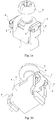
- connection terminal comprises a cage 1 housing a contact pad 2 whose movement relative to the cage 1 is caused by a screw 3.
- the teeth 4, 5 projecting from the contact pad 2 are located on either side of the cage 1, and oriented along an axis parallel to that of the screw 3, points directed in the direction of tightening thereof.
- the end portions 6, 7 of the clamping plate are oriented at opposite each other and therefore have opposite end edges. This is why, one of said portions is provided with lateral fins 8, 9 offering oriented edges like the end edge of portion 6.
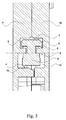
- each tooth 4, 5 is embedded in the clamping in stops molded in the half-shells. To that the main function of the invention is realized, it is important that each tooth cooperates with a stopper of a half-shell, hence their location substantially symmetrical with respect to a vertical longitudinal median plane cutting the contact plate 2, giving a representation equivalent to that of figure 2.
- the terminal environment consisting of the housing 10 mounted in the half-shells 11, 12 and the elements located in the vicinity immediate said housing 10 are also shown.
- the housing 10 mounted in the half-shells 11, 12 and the elements located in the vicinity immediate said housing 10 are also shown.
- the geometry of the housing 10 for two main aspects.
- each housing there are stops in which the points 4, 5 are anchored.
- the stop associated with the half-shell 11 is referenced 13, while the stop of the other half-shell 12 bears the reference 14. Due to the almost anchoring contact pad 2 immediately from the start of tightening, said pad 2 is fixed, and the connection of the conductor with the terminal, obtained by the jamming of the stripped end of said conductor between plate 2 and one of the walls of the cage, can only be produced if said cage is movable in his home.
- cage 1 there is a sliding of the only element still endowed with a degree of freedom in the housing 10, that is to say the cage 1, as the tightening or loosening.
- cage 1 When no conductor is connected, cage 1 is located in the vicinity of the wall of the housing 10 closest to the base of the apparatus. In the clamping position, said cage 1 is on the contrary located at proximity of the wall of the housing 10 surrounding the screw 3.
- the volume of the housing 10 is provided accordingly, and allows a movement of the cage 1 compatible with the tightening requirements.
- all of the mechanical connections act as a classic motion transformer, transforming rotary motion printed on the screw 3 in a translational movement of the cage 1.
- the two figures 3 and 4 are two opposite views from a single cutting surface. They clearly show the respective locations of teeth 4, 5 laterally with respect to the contact pad 2, so as to be locate each in a half-housing of each half-shell 11, 12.
- figure 5 The main interest of figure 5 is to show the relative positioning axial of the cage 1 and of the contact plate 2.
- the cutting plane, on the left side of the figure, go into tooth 5 which we see the exact positioning on the one hand with respect to the end portion 7, and on the other hand on the stop 14.
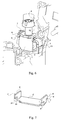
- Figure 6 shows the elements of the previous figures 2 to 5, but in perspective. It highlights the cooperation of tooth 4 with the stop 13. It also specifies the configuration of the cage 1 / plate assembly. contact 2: cage 1 is housed in volume 10, while the portions ends 6 and 7 of the contact plate 2 are nestled outside said volume, and therefore do not hinder the travel of the cage 1 when it moves in rectilinear translation.
- FIG. 7 represents a possible variant of the contact plate 2 '.
- the end portion 7 ' is strictly identical to the portion 7 of the part described above, with two lateral fins 8 ', 9' and a tooth 5 'anchor.
- the second end portion 6 ′ is positioned so that that it forms a U with the first. It has a 20 'notch allowing the addition of an additional tooth 21 'on a fin 22', in more than tooth 4 'identical to tooth 4 of contact pad 2 previously described.
Landscapes
- Connections Arranged To Contact A Plurality Of Conductors (AREA)
Abstract
caractérisée en ce que ladite plaquette de contact 2 comporte des moyens d'ancrage 4, 5 aux deux demi-coques 11, 12, afin que le couple exercé sur la vis 3 pendant le serrage soit transmis auxdites demi-coques 11, 12 de manière qu'elles se resserrent au niveau de leurs surfaces de jonction.
Description
- Les figures 1a et 1b sont des vues en perspective d'une borne de raccordement complète selon l'invention ;
- La figure 2 est une vue en coupe selon le plan de jonction des demi-coques, de ladite borne dans son logement représenté schématiquement ;
- La figure 3 est une coupe de la représentation de la figure 2, vue dans la direction des flèches III ;
- La figure 4 est également une coupe de la représentation de la figure 2, mais vue dans la direction des flèches IV ;
- La figure 5 est enfin une autre coupe de la représentation de la figure 2, vue dans la direction des flèches V ;
- La figure 6 est une vue en perspective d'une borne de raccordement selon la présente invention, dans son environnement immédiat également représenté en figure 2 ; et
- La figure 7 est une variante de la plaquette de contact vue en perspective.
Claims (6)
- Borne de raccordement d'un conducteur à un appareillage électrique de type modulaire, disposée dans un boítier formé de deux demi-coques 11, 12 assemblées dans un logement 10 prévu à cet effet, ladite borne de raccordement comportant une cage 1 logeant une plaquette de contact 2 coopérant avec une vis 3 en vue de fixer par serrage ou de libérer par desserrage ledit conducteur,
caractérisée en ce que ladite plaquette de contact 2 comporte des moyens d'ancrage 4, 5 aux deux demi-coques 11, 12, afin que le couple exercé sur la vis 3 pendant le serrage soit transmis auxdites demi-coques 11, 12 de manière qu'elles se resserrent au niveau de leurs surfaces de jonction. - Borne de raccordement d'un conducteur à un appareillage électrique de type modulaire selon la revendication 1, caractérisée en ce que les moyens d'ancrage de la plaquette de contact 2, 2' comportent des dents 4, 5 faisant saillies vers des butées 13, 14 pratiquées dans lesdites demi-coques 11, 12, destinées à s'incruster dans lesdites butées 13, 14 au fur et à mesure de l'exercice du couple de serrage sur la vis 3.
- Borne de raccordement d'un conducteur à un appareillage électrique de type modulaire selon la revendication 2, caractérisée en ce que lesdites dents 4, 5 sont situées sur des chants de ladite plaquette de contact 2 orientés à l'opposé de la tête de ladite vis 3, la pointe de chaque dent 4, 5 s'incrustant selon un axe parallèle à celui de la vis 3, dans le sens de serrage axial de cette dernière.
- Borne de raccordement d'un conducteur à un appareillage électrique de type modulaire selon la revendication 3, caractérisée en ce que chaque plaquette de contact 2 comporte au moins une dent 4, 5 coopérant avec une surface d'une butée 13, 14 d'allure sensiblement perpendiculaire à l'axe de la vis 3 située sur chacune des demi-coques 11, 12 formant le boítier.
- Borne de raccordement d'un conducteur à un appareillage électrique de type modulaire selon la revendication 4, caractérisée en ce que la plaquette de contact 2 comporte un corps central plan doté de deux portions 6, 7 d'extrémités perpendiculaires audit corps, dont l'une est munie d'ailettes 8, 9 latérales dépassant de chaque côté dudit corps central, l'une des dents 4 étant située sur le chant d'extrémité de la portion perpendiculaire 6 sans ailette, décalée vers le côté, l'autre dent 5 étant située sur le chant parallèle de l'ailette 7 située de l'autre côté par rapport à l'axe longitudinal de la plaquette 2, les deux dents 4, 5 pointant dans la même direction.
- Borne de raccordement d'un conducteur à un appareillage électrique de type modulaire selon la revendication 4, caractérisée en ce que la plaquette de contact 2' a une forme en U dont l'extrémité des jambages comporte des ailettes latérales 8', 9', 22' dont les chants parallèles, orientés vers la base du U, comportent chacun une dent 7', 21', lesdites dents 7', 21' étant situées de part et d'autre de l'axe longitudinal de ladite base du U, une dent 4' étant au surplus localisée sur l'ailette 22' en face de la dent 21'.
Priority Applications (2)
| Application Number | Priority Date | Filing Date | Title |
|---|---|---|---|
| EP19960440102 EP0847105B1 (fr) | 1996-11-29 | 1996-11-29 | Borne de raccordement d'un conducteur à un appareillage électrique de type modulaire |
| DE1996602758 DE69602758T2 (de) | 1996-11-29 | 1996-11-29 | Leiteranschlussklemme eines modularen elektrischen Gerätes |
Applications Claiming Priority (1)
| Application Number | Priority Date | Filing Date | Title |
|---|---|---|---|
| EP19960440102 EP0847105B1 (fr) | 1996-11-29 | 1996-11-29 | Borne de raccordement d'un conducteur à un appareillage électrique de type modulaire |
Publications (2)
| Publication Number | Publication Date |
|---|---|
| EP0847105A1 true EP0847105A1 (fr) | 1998-06-10 |
| EP0847105B1 EP0847105B1 (fr) | 1999-06-02 |
Family
ID=8225426
Family Applications (1)
| Application Number | Title | Priority Date | Filing Date |
|---|---|---|---|
| EP19960440102 Expired - Lifetime EP0847105B1 (fr) | 1996-11-29 | 1996-11-29 | Borne de raccordement d'un conducteur à un appareillage électrique de type modulaire |
Country Status (2)
| Country | Link |
|---|---|
| EP (1) | EP0847105B1 (fr) |
| DE (1) | DE69602758T2 (fr) |
Cited By (5)
| Publication number | Priority date | Publication date | Assignee | Title |
|---|---|---|---|---|
| WO2003041226A1 (fr) * | 2001-11-06 | 2003-05-15 | Abb Service S.R.L. | Borne pour dispositif modulaire basse tension |
| DE10111431B4 (de) * | 2000-03-10 | 2008-09-25 | Schneider Electric Industries S.A. | Leiteranschlussklemme |
| EP2019449A2 (fr) | 2007-07-26 | 2009-01-28 | Abb Ag | Borne de connexion à vis et son procédé de fabrication |
| CN103138058A (zh) * | 2011-12-01 | 2013-06-05 | 西门子公司 | 电缆接线座 |
| CN106911054A (zh) * | 2017-04-01 | 2017-06-30 | 菲尼克斯亚太电气(南京)有限公司 | 一种外置式开关螺钉转接组件 |
Families Citing this family (1)
| Publication number | Priority date | Publication date | Assignee | Title |
|---|---|---|---|---|
| DE102007006367A1 (de) * | 2007-02-08 | 2008-08-21 | Siemens Ag | Leitungsschutzschalter mit Klemme |
Citations (5)
| Publication number | Priority date | Publication date | Assignee | Title |
|---|---|---|---|---|
| US3559156A (en) * | 1968-01-18 | 1971-01-26 | Westinghouse Electric Corp | Electrical device with improved terminal means |
| DE1790153A1 (de) * | 1967-09-29 | 1972-01-20 | Telemeccanica Elettrica Ohg Ri | Klemme fuer den Anschluss elektrischer Leiter |
| DE3417010A1 (de) * | 1984-05-09 | 1985-11-14 | Karl Lumberg GmbH & Co, 5885 Schalksmühle | Elektrische anschlussklemme |
| EP0541459A1 (fr) | 1991-11-07 | 1993-05-12 | Schneider Electric Sa | Borne à vis pour un appareil électrique à boîtier isolant moulant |
| DE4329097C1 (de) * | 1993-08-30 | 1994-09-29 | Lumberg Karl Gmbh & Co | Elektrische Anschlußklemme für Leiterplatten und Verfahren zu ihrer Herstellung |
-
1996
- 1996-11-29 DE DE1996602758 patent/DE69602758T2/de not_active Expired - Lifetime
- 1996-11-29 EP EP19960440102 patent/EP0847105B1/fr not_active Expired - Lifetime
Patent Citations (5)
| Publication number | Priority date | Publication date | Assignee | Title |
|---|---|---|---|---|
| DE1790153A1 (de) * | 1967-09-29 | 1972-01-20 | Telemeccanica Elettrica Ohg Ri | Klemme fuer den Anschluss elektrischer Leiter |
| US3559156A (en) * | 1968-01-18 | 1971-01-26 | Westinghouse Electric Corp | Electrical device with improved terminal means |
| DE3417010A1 (de) * | 1984-05-09 | 1985-11-14 | Karl Lumberg GmbH & Co, 5885 Schalksmühle | Elektrische anschlussklemme |
| EP0541459A1 (fr) | 1991-11-07 | 1993-05-12 | Schneider Electric Sa | Borne à vis pour un appareil électrique à boîtier isolant moulant |
| DE4329097C1 (de) * | 1993-08-30 | 1994-09-29 | Lumberg Karl Gmbh & Co | Elektrische Anschlußklemme für Leiterplatten und Verfahren zu ihrer Herstellung |
Cited By (8)
| Publication number | Priority date | Publication date | Assignee | Title |
|---|---|---|---|---|
| DE10111431B4 (de) * | 2000-03-10 | 2008-09-25 | Schneider Electric Industries S.A. | Leiteranschlussklemme |
| WO2003041226A1 (fr) * | 2001-11-06 | 2003-05-15 | Abb Service S.R.L. | Borne pour dispositif modulaire basse tension |
| EP2019449A2 (fr) | 2007-07-26 | 2009-01-28 | Abb Ag | Borne de connexion à vis et son procédé de fabrication |
| EP2019449A3 (fr) * | 2007-07-26 | 2009-12-16 | Abb Ag | Borne de connexion à vis et son procédé de fabrication |
| CN101355199B (zh) * | 2007-07-26 | 2012-11-28 | Abb股份有限公司 | 螺钉接线端子及其制造方法 |
| CN103138058A (zh) * | 2011-12-01 | 2013-06-05 | 西门子公司 | 电缆接线座 |
| CN106911054A (zh) * | 2017-04-01 | 2017-06-30 | 菲尼克斯亚太电气(南京)有限公司 | 一种外置式开关螺钉转接组件 |
| CN106911054B (zh) * | 2017-04-01 | 2024-03-19 | 菲尼克斯亚太电气(南京)有限公司 | 一种外置式开关螺钉转接组件 |
Also Published As
| Publication number | Publication date |
|---|---|
| DE69602758D1 (de) | 1999-07-08 |
| DE69602758T2 (de) | 2000-03-02 |
| EP0847105B1 (fr) | 1999-06-02 |
Similar Documents
| Publication | Publication Date | Title |
|---|---|---|
| EP0511111B1 (fr) | Connexion électrique et boîtier d'appareil électrique comportant une telle connexion | |
| FR2639481A1 (fr) | Dispositif formant connecteur electrique | |
| EP0847105B1 (fr) | Borne de raccordement d'un conducteur à un appareillage électrique de type modulaire | |
| EP0784355A1 (fr) | Agencement d'interconnexion pour appareillage électrique, notamment pour appareillage de type bloc de jonction, et boîtier équipé d'une tel agencement | |
| FR2808618A1 (fr) | Disjoncteur comportant, dans une enveloppe remplie d'un gaz dielectrique sous pression, un ensemble mobile | |
| EP0893846B1 (fr) | Appareil électrique portant un support de contact fixe et une borne de raccordement | |
| EP0559585A1 (fr) | Borne de raccordement à étrier d'épaisseur variable et à écrou serti | |
| EP0541459B1 (fr) | Borne à vis pour un appareil électrique à boîtier isolant moulant | |
| FR2601512A1 (fr) | Connecteur electrique a force d'insertion nulle | |
| FR2766628A1 (fr) | Peigne d'interconnexion pour alignement de bornes de raccordement electrique d'un appareillage et module(s) de logement d'appareillage correspondant(s) | |
| EP0552114B1 (fr) | Borne de raccordement multiple pour appareillage électrique modulaire | |
| FR2752647A1 (fr) | Dispositif de borne pour un equipement electrique | |
| EP0633588A1 (fr) | Accessoire de raccordement | |
| EP1531525A1 (fr) | Serre-câble à plage de serrage èlargie et bloc de jonction muni d'un tel serre-câble | |
| FR2488452A1 (fr) | Borne pour l'ancrage rapide de conducteurs sur des " des " d'appareils electriques | |
| FR2709883A1 (fr) | Contact électrique à rappel élastique. | |
| EP0521803B1 (fr) | Dispositif de connexion et d'alimentation électrique | |
| FR2690011A1 (fr) | Borne de connexion électrique de type serre-fil à vis. | |
| FR2858119A1 (fr) | Dispositif de raccordement electrique a contact protege | |
| EP2135328B1 (fr) | Bloc de jonction et barrette de liaison | |
| FR2597664A1 (fr) | Dispositif de connexion electrique du type a perforation d'isolant | |
| FR2849291A1 (fr) | Dispositif de raccordement electrique muni de porte-reperes pouvant immobiliser des reperes de tailles differentes | |
| EP0763871B1 (fr) | Borne de raccordement d'un appareil d'installation électrique | |
| EP1056156A1 (fr) | Borne élastique à insert de butée | |
| FR2506528A1 (fr) | Dispositif de connexion destine au raccordement d'une extremite d'un fil a un appareil electrique |
Legal Events
| Date | Code | Title | Description |
|---|---|---|---|
| PUAI | Public reference made under article 153(3) epc to a published international application that has entered the european phase |
Free format text: ORIGINAL CODE: 0009012 |
|
| 17P | Request for examination filed |
Effective date: 19961210 |
|
| AK | Designated contracting states |
Kind code of ref document: A1 Designated state(s): CH DE ES FI FR IT LI SE |
|
| GRAG | Despatch of communication of intention to grant |
Free format text: ORIGINAL CODE: EPIDOS AGRA |
|
| GRAG | Despatch of communication of intention to grant |
Free format text: ORIGINAL CODE: EPIDOS AGRA |
|
| GRAH | Despatch of communication of intention to grant a patent |
Free format text: ORIGINAL CODE: EPIDOS IGRA |
|
| GRAH | Despatch of communication of intention to grant a patent |
Free format text: ORIGINAL CODE: EPIDOS IGRA |
|
| AKX | Designation fees paid |
Free format text: CH DE ES FI FR IT LI SE |
|
| RBV | Designated contracting states (corrected) |
Designated state(s): CH DE ES FI FR IT LI SE |
|
| GRAA | (expected) grant |
Free format text: ORIGINAL CODE: 0009210 |
|
| AK | Designated contracting states |
Kind code of ref document: B1 Designated state(s): CH DE ES FI FR IT LI SE |
|
| PG25 | Lapsed in a contracting state [announced via postgrant information from national office to epo] |
Ref country code: SE Free format text: THE PATENT HAS BEEN ANNULLED BY A DECISION OF A NATIONAL AUTHORITY Effective date: 19990602 Ref country code: FI Free format text: LAPSE BECAUSE OF NON-PAYMENT OF DUE FEES Effective date: 19990602 Ref country code: ES Free format text: THE PATENT HAS BEEN ANNULLED BY A DECISION OF A NATIONAL AUTHORITY Effective date: 19990602 |
|
| REG | Reference to a national code |
Ref country code: CH Ref legal event code: EP |
|
| REF | Corresponds to: |
Ref document number: 69602758 Country of ref document: DE Date of ref document: 19990708 |
|
| ITF | It: translation for a ep patent filed | ||
| PLBE | No opposition filed within time limit |
Free format text: ORIGINAL CODE: 0009261 |
|
| STAA | Information on the status of an ep patent application or granted ep patent |
Free format text: STATUS: NO OPPOSITION FILED WITHIN TIME LIMIT |
|
| 26N | No opposition filed | ||
| REG | Reference to a national code |
Ref country code: CH Ref legal event code: PL |
|
| PGFP | Annual fee paid to national office [announced via postgrant information from national office to epo] |
Ref country code: CH Payment date: 20010806 Year of fee payment: 5 |
|
| REG | Reference to a national code |
Ref country code: CH Ref legal event code: AEN Free format text: LE BREVET A ETE REACTIVE SELON LA DEMANDE DE POURSUITE DE LA PROCEDURE DU 06.08.2001. |
|
| PG25 | Lapsed in a contracting state [announced via postgrant information from national office to epo] |
Ref country code: LI Free format text: LAPSE BECAUSE OF NON-PAYMENT OF DUE FEES Effective date: 20011130 Ref country code: CH Free format text: LAPSE BECAUSE OF NON-PAYMENT OF DUE FEES Effective date: 20011130 |
|
| REG | Reference to a national code |
Ref country code: CH Ref legal event code: PL |
|
| REG | Reference to a national code |
Ref country code: FR Ref legal event code: PLFP Year of fee payment: 20 |
|
| PGFP | Annual fee paid to national office [announced via postgrant information from national office to epo] |
Ref country code: IT Payment date: 20151113 Year of fee payment: 20 Ref country code: DE Payment date: 20151119 Year of fee payment: 20 |
|
| PGFP | Annual fee paid to national office [announced via postgrant information from national office to epo] |
Ref country code: FR Payment date: 20151123 Year of fee payment: 20 |
|
| REG | Reference to a national code |
Ref country code: DE Ref legal event code: R071 Ref document number: 69602758 Country of ref document: DE |