EP0847939A1 - Verfahren und Vorrichtung zum Kommissionieren - Google Patents
Verfahren und Vorrichtung zum Kommissionieren Download PDFInfo
- Publication number
- EP0847939A1 EP0847939A1 EP97121957A EP97121957A EP0847939A1 EP 0847939 A1 EP0847939 A1 EP 0847939A1 EP 97121957 A EP97121957 A EP 97121957A EP 97121957 A EP97121957 A EP 97121957A EP 0847939 A1 EP0847939 A1 EP 0847939A1
- Authority
- EP
- European Patent Office
- Prior art keywords
- containers
- container
- slow
- speed
- flow channels
- Prior art date
- Legal status (The legal status is an assumption and is not a legal conclusion. Google has not performed a legal analysis and makes no representation as to the accuracy of the status listed.)
- Granted
Links
Images


Classifications
-
- B—PERFORMING OPERATIONS; TRANSPORTING
- B65—CONVEYING; PACKING; STORING; HANDLING THIN OR FILAMENTARY MATERIAL
- B65G—TRANSPORT OR STORAGE DEVICES, e.g. CONVEYORS FOR LOADING OR TIPPING, SHOP CONVEYOR SYSTEMS OR PNEUMATIC TUBE CONVEYORS
- B65G1/00—Storing articles, individually or in orderly arrangement, in warehouses or magazines
- B65G1/02—Storage devices
- B65G1/04—Storage devices mechanical
- B65G1/137—Storage devices mechanical with arrangements or automatic control means for selecting which articles are to be removed
-
- B—PERFORMING OPERATIONS; TRANSPORTING
- B65—CONVEYING; PACKING; STORING; HANDLING THIN OR FILAMENTARY MATERIAL
- B65G—TRANSPORT OR STORAGE DEVICES, e.g. CONVEYORS FOR LOADING OR TIPPING, SHOP CONVEYOR SYSTEMS OR PNEUMATIC TUBE CONVEYORS
- B65G1/00—Storing articles, individually or in orderly arrangement, in warehouses or magazines
- B65G1/02—Storage devices
- B65G1/04—Storage devices mechanical
- B65G1/06—Storage devices mechanical with means for presenting articles for removal at predetermined position or level
- B65G1/08—Storage devices mechanical with means for presenting articles for removal at predetermined position or level the articles being fed by gravity
-
- B—PERFORMING OPERATIONS; TRANSPORTING
- B65—CONVEYING; PACKING; STORING; HANDLING THIN OR FILAMENTARY MATERIAL
- B65G—TRANSPORT OR STORAGE DEVICES, e.g. CONVEYORS FOR LOADING OR TIPPING, SHOP CONVEYOR SYSTEMS OR PNEUMATIC TUBE CONVEYORS
- B65G1/00—Storing articles, individually or in orderly arrangement, in warehouses or magazines
- B65G1/02—Storage devices
- B65G1/04—Storage devices mechanical
- B65G1/137—Storage devices mechanical with arrangements or automatic control means for selecting which articles are to be removed
- B65G1/1373—Storage devices mechanical with arrangements or automatic control means for selecting which articles are to be removed for fulfilling orders in warehouses
- B65G1/1378—Storage devices mechanical with arrangements or automatic control means for selecting which articles are to be removed for fulfilling orders in warehouses the orders being assembled on fixed commissioning areas remote from the storage areas
-
- B—PERFORMING OPERATIONS; TRANSPORTING
- B65—CONVEYING; PACKING; STORING; HANDLING THIN OR FILAMENTARY MATERIAL
- B65G—TRANSPORT OR STORAGE DEVICES, e.g. CONVEYORS FOR LOADING OR TIPPING, SHOP CONVEYOR SYSTEMS OR PNEUMATIC TUBE CONVEYORS
- B65G2209/00—Indexing codes relating to order picking devices in General
- B65G2209/04—Indication location means
Definitions
- the invention relates to a method for picking in Containers articles, the corresponding container of at least one container storage at least one picking workstation fed and at several, in the area of the picking workplace available removal positions for the purpose of removing the article can be provided, with each removal position a flow channel is assigned to each flow channel at the picking workstation facing end has the respective removal position in which the Pickers can take items from the container, each Pass-through channel continues at its point away from the picking work station Area has a transfer area where the supplied from the container store Containers are passed to the flow channel and each Pass-through channel a transport device for transporting the transferred Containers from the transfer area to the removal position.
- the invention relates to a system for picking in Articles located containers, the corresponding container by means of a Conveying device of at least one container store at least one Picking workstation fed and through flow channels at several, in Picking positions in the area of the picking work station at Purposes of removal of the articles are provided, according to the Generic term of claim 6.
- High-speed items are items that are required frequently or in large quantities while slow-moving items are such that are rare or in small Quantities are needed.
- the orders in the respective storage areas only be partially processed, i.e. picking the slow-moving items and the high-speed item is made independently and by different staff, this means a split of the Picking order and an associated higher potential error rate as well as additional effort in the subsequent merging.
- the invention is therefore essentially based on the object Efficiency of a picking process in which both high-speed items as well as slow-moving items have to be picked.
- the invention is also based on the object of a corresponding one To create a system that enables more efficient order picking.
- the individual containers as High-speed containers or slow-speed containers that are defined individual flow channels partly as flow channels for high-speed and partially defined as through-flow channels for slow-moving (where these Flow channels through the warehouse management computer dynamically in your Functionality from high-speed to slow-speed flow channels and can be changed if necessary) that the high-speed container the high-speed flow channels and the low-speed containers Slow-speed pass-through channels are supplied that once in the Removal position of the high-speed container is emptied, this from his Removal position removed from the flow channel and another, in the flow channel located high-speed container is brought into the removal position that the low-speed containers are fed to the low-speed flow channels be that only one slow-moving container in the Slow-speed flow channel is located, and that after removal of the desired Article from the slow-moving container the partially filled slow-moving container is moved against the feed direction in the direction of the transfer area and then transported back to the at least one container store and is stored there.
- the task essentially becomes solved that in the system for picking according to the generic term of Claim 6 at least part of the flow channels a return position for the Containers which are opposite the removal position in the direction of Transfer area is set back and that the conveyor means for Includes the container located in the return position.
- the order picker Since the order picker has both the High-speed items as well as the slow-speed items provided longer distances of the order picker are avoided.
- the Picking is carried out for both types of article according to the principle of "goods for Man "so that the deployment of more highly qualified personnel can be avoided can. After containers with slow-moving items after removing the desired items can be returned to the container warehouse Container positions at the order picker's workplace are not unnecessarily reduced goods not needed blocked. It can also be used for both slow-speed items the same stock can also be used for high-speed items. It will be one compact storage possible (no separate storage areas for slow-moving and High-speed item) and uniform storage technology can be used will.
- the system according to the invention is thus compared to the known one State of the art more efficient, has a lower error rate and requires less space and less manpower.
- the Low-speed container from the slow-speed flow channels on Container storage uses the same conveyor as for feeding the Containers from the container storage to the flow channels, which in a cost-saving Ways existing facilities can be used twice.
- the technical requirements for the system according to the invention to carry out the method can then be kept particularly low, if part of the flow channels a return position for the slow-moving containers has, which is opposite the removal position in the direction of Transfer area is set back, the conveyor, which in particular a shelf conveyor can be means for receiving the in the Return position located container.
- the conveyor which in particular a shelf conveyor can be means for receiving the in the Return position located container.
- the transport device of the flow channels as an inclined path, in particular a roller path of the containers placed in the transfer area due to gravity Slide the removal position.
- a separate drive for the transport equipment of the Flow channels are not necessary in this case.
- the return position can be either activatable stop for the container can be defined, with more preferred Training the stop by pushing the container back from the Removal position can be activated in the return position.
- the flow channels for the slow-running machines differ from the Pass-through channels of the high-speed runner practically only through the additional activatable stop or lock. This also makes it possible Flow channels, which are equipped for slow-running, optionally also for To use high-speed, by deactivating the stop or the lock.
- the stop or the lock can both be an active component (e.g. with pneumatics) as well as a passive component (e.g. mechanical element with return spring or similar).
- the invention is System continues to be characterized by a high-bay warehouse with at least one Storage rack in which the flow channels are integrated, and by at least one Shelf conveyor that removes the containers from the storage rack Feed channels and that in the return position of the feed channels slow-moving containers located to the storage rack storage spaces returns and stores there. This results in a particularly space-saving Arrangement with the shortest possible funding routes.
- the at least one storage rack preferably has double depth Parking spaces and the return positions of the slow-moving containers within the flow channels correspond to the positions of the Racking-away parking spaces of the double-deep storage rack, i.e., the Return positions are essentially vertical above or below the Appropriate parking spaces arranged so that the shelf conveyor on these return positions can take over containers as well the containers located on the storage rack at the rear.
- the shelf-type conveyors intended for loading and unloading the storage rack therefore do not need any additional for the return of the slow-moving containers Mechanics.
- the system comprises a unit consisting of two parallel shelf aisles, at least one along each shelf aisle movable shelf conveyor, arranged on both sides of the two shelf aisles Storage racks, flow channels in the two middle, facing each other Storage racks and one between these two middle storage racks order picking workstation.
- a unit consisting of two parallel shelf aisles, at least one along each shelf aisle movable shelf conveyor, arranged on both sides of the two shelf aisles Storage racks, flow channels in the two middle, facing each other Storage racks and one between these two middle storage racks order picking workstation.
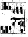
- the picking system includes a high-bay warehouse with parallel arranged storage racks 10, 12, 14 and 16, in which transport container 18 in double deep compartments are stored. Between storage racks 10 and 12 as well 14 and 16, rack aisles 20 and 22 are defined, in which shelf conveyors 24, 26 are movable.
- the shelf conveyors operate on the shelf aisles 20 located storage racks 10 and 12 and the shelf conveyor 26 serve the shelf aisles 22 and 14 storage racks Suitable load suspension devices that are extendable to the front or rear storage spaces on the storage racks outsource.
- the adjacent storage racks 12, 14 are each other spaced to make room for picking workplaces.
- the picking workplaces are also on the floor. Then no platform is necessary.
- a conveyor 40 upstream which is parallel to the storage rack or Picking loop runs over and over with the picking loop Connecting tracks 42 (see FIG. 2) is connected to the Customer order containers from the picking loop to the individual work station feed or the processed customer order containers to the picking loop attributed.
- the flow channels 44, 46 each point to the work station 34 inclined roller conveyor 50, one towards the respective rack conveyor 24 or 26 open transfer area 52 and at the end of the workplace Removal position 54 on.
- the length of each roller conveyor 50 is designed that it can accommodate three transport containers 18 arranged one behind the other.
- the respective removal position 54 is determined by one at the end of each roller conveyor 50 arranged stop defined for the transport container.
- the means of Shelf conveyors 24, 26 transport containers outsourced from the storage racks are the load handler of the respective shelf conveyor Transfer areas 52 of the flow channels are fed and slide from here due to gravity on the roller conveyor 50 in their respective removal position or, if this is already occupied, to the next middle position or, if this is already occupied, in the rearmost position.
- Some of the flow channels namely those in the drawing with the Flow channels designated by reference number 46 have a lock 56 which is shown in FIG a blocking position can be activated or deactivated in a passage position.
- the lock 56 At the Entry of a transport container into a flow channel 46 is the lock 56 always deactivated, so that the container slide into its removal position 54 can while pushing a container back into the transfer area 58 - as will be explained in more detail below - is activated so that the Transport container located in the transfer area strikes the lock 56 and is thus held in the transfer area 58.
- Control of lock 56 can either mechanically or electrically / electronically.
- the individual customer orders are picked with the help the paperless picking system and the automatic Container conveyor technology.
- the sales orders are overlaid ERP system recorded and accepted and after a possible Availability check either at cyclical intervals or online to the Hand over warehouse management system.
- the warehouse management system takes over then the optimization of customer orders with a view to effective Picking.
- the customer order containers are placed on the picking loop 30 and a connecting track 42 fed to the conveyor 40 and from here parked at a picking station.
- a corresponding, on The picking station of the customer order container is shown in FIGS. 2 and 3 marked with "K".
- the through the Picking emerging empty transport containers and / or Transport container from a specially designed empty container storage in container conveyor technology can be used.
- Each picking loop 30 connects the individual Picking stations 48 and ensures the exchange of the containers for the Removal of the full customer order containers and for the supply of empty ones Containers. Every customer order container is very likely to be on completely filled in a single picking loop. The remaining Customer order containers must have a second one or, if necessary, a second one Approach further picking loops. To that end, they are over Vertical conveyor 62 (see FIG. 1) to a leveling conveyor technology level transported and can use the vertical conveyor of the next Reach picking loops.
- the transport containers 18 located in the storage racks are each according to their content, within the warehouse management system as a slow runner or defined as high-speed.
- High-speed transport containers are used by the Shelf-type conveyors are always fed to the high-speed continuous channels 44, while slow-speed transport containers always use the slow-speed flow channels 46 are supplied.
- In the high-speed flow channels 44 can provide a maximum of three transport containers of the respective article will. If two containers become empty due to the order picking, they will automatically two transport containers of the same article from the shelf conveyor pushed from behind (if necessary also other articles). Once a Fast-moving storage container is empty, it is picked manually by the order picker 38 removed from the removal position 54 of the flow channel 44 and on the Conveyor 40 set, from where the empty container to the picking loop 30 is supplied.
- Slow-speed transport containers are given the slow-speed flow channels 46 assigned and in each low-speed passage 46 only one low-speed transport container is provided at a time.
- the Slow-moving storage container manually by the order picker by approx Container length pushed back over the lock 56 and the lock 56 activated. This lock then prevents the slow-moving transport container from rolling back to removal position 54.
- the slow-moving transport container which is then in the return position 58 (dashed Position in Figure 3), then by means of a telescope of the load handling device of the shelf conveyor are taken over by the shelf conveyor and back in the storage racks are stored.
- the order picker is informed by suitable display means regarding the individual picking processes, which is above the individual Flow channels, specialist displays 64 are provided (see FIG. 2), on which the Withdrawal quantity and further information are shown.
- the process too the pushing back of a storage container for slow-speed flow channels 44 is visualized for the order picker with the help of the specialist display symbolism.
- the order picker according to the request of the specialist advertisement, the corresponding transport container pushed back and this on the compartment display acknowledged, the shelf conveyor is automatically prompted to do so Pick up slow-moving transport containers and put them back on the storage racks store.
- the customer order containers completed in the picking are from the picking loops 30 by means of vertical container conveyors Storage / retrieval level of the conveyor technology transported and from here to various Criteria transported.
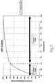
- FIG is sketched as a diagram.
- Figure 4 shows the relationship between Item range and order items. It follows that 80% of the Orderline volume can be realized with 20% of the items, while 20% of the Orderline volume can be realized with 80% of the items. The former 20% are the high-speed items, the other 80% are the low-speed items.
- the Invention is now based on the assumption that the high-speed items are permanently available Picking will be provided while the slow-moving item in one and dynamically deployed to the same system, i.e. as required.
- the invention enables the installed Use technology simultaneously for the provision of picking.
- the High-speed machines are provided in continuous operation, the low-speed machines on Exchange spaces. Due to the identical picking process for Fast and slow runner as well as picking all items in One system has the advantage of a uniform technology. Through a flexible and dynamic article classification in quick and Slow-moving results in a high degree of flexibility. From shortening the effective Order picking routes through dynamic exchange stations and an efficient one Operator guidance by means of paperless picking (specialist advertisements) follows high picking performance. Due to the optimal picking performance there is a high one Personnel utilization. Space is saved by the intelligent and temporary Provision of the slow runner on exchange pitches as well as due to the Reduced picking areas thanks to the changeover strategy and integrated, mechanized storage achieved. Overall, that stands out System according to the invention characterized by a high level of economy.
Landscapes
- Engineering & Computer Science (AREA)
- Mechanical Engineering (AREA)
- Warehouses Or Storage Devices (AREA)
- Eye Examination Apparatus (AREA)
Abstract
Description
- 10
- Lagerregale
- 12
- Lagerregale
- 14
- Lagerregale
- 16
- Lagerregale
- 18
- Transportbehälter
- 20
- Regalgassen
- 22
- Regalgassen
- 24
- Regalförderzeuge
- 26
- Regalförderzeuge
- 30
- Kommissionier-Loop
- 34
- Kommissionier-Arbeitsplätze
- 36
- Plattform
- 38
- Kommissionierer
- 40
- Fördereinrichtung
- 42
- Verbindungsbahnen
- 44
- Durchlaufkanäle
- 46
- Durchlaufkanäle
- 48
- Kommissionierbahnhof
- 50
- Rollenbahn
- 52
- Übergabebereich
- 54
- Entnahmeposition
- 56
- Sperre
- 58
- Rückgabeposition
- 62
- Vertikalförderer
- 64
- Fachanzeige
Claims (17)
- Verfahren zum Kommissionieren von in Behältern (18) befindlichen Artikeln, wobei die entsprechenden Behälter von mindestens einem Behälterlager (10, 12, 14, 16) mindestens einem Kommissionier-Arbeitsplatz (34) zugeführt und an mehreren, im Bereich des Kommissionier-Arbeitsplatzes befindlichen Entnahmepositionen (54) zum Zwecke der Entnahme der Artikel bereitgestellt werden, wobeijeder Entnahmeposition (54) ein Durchlaufkanal (44, 46) zugeordnet ist,jeder Durchlaufkanal (44, 46) an seinem dem Kommissionier-Arbeitsplatz zugewandten Ende die jeweilige Entnahmeposition (54) aufweist, in der der Kommissionierer dem Behälter Artikel entnehmen kann,jeder Durchlaufkanal (44, 46) an seinem dem Kommissionier-Arbeitsplatz abgewandten Bereich einen Übergabebereich (52) aufweist, wo die vom Behälterlager zugeführten Behälter an den Durchlaufkanal übergeben werden, undjeder Durchlaufkanal (44, 46) eine Transporteinrichtung (50) zum Transport der übergebenen Behälter vom Übergabebereich (52) zur Entnahmeposition (54) aufweist,
gekennzeichnet durch folgende Merkmale:die einzelnen Behälter (18) werden als Schnellläufer-Behälter oder als Langsamläufer-Behälter definiert,die einzelnen Durchlaufkanäle (44, 46) werden teilweise als Durchlaufkanäle (44) für Schnellläufer und teilweise als Durchlaufkanäle (46) für Langsamläufer definiert,die Schnellläufer-Behälter werden den Schnellläufer-Durchlaufkanälen (44) und die Langsamläufer-Behälter den Langsamläufer-Durchlaufkanälen (46) zugeführt,sobald ein in der Entnahmeposition (54) befindlicher Schnellläufer-Behälter entleert ist, wird er aus seiner Entnahmeposition (54) vom Durchlaufkanal (44) entfernt und ein weiterer, im Durchlaufkanal befindlicher Schnellläufer-Behälter wird in die Entnahmeposition verbracht,den Langsamläufer-Durchlaufkanälen (46) werden die Langsamläufer-Behälter so zugeführt, daß sich immer nur ein einziger Langsamläufer-Behälter im Langsamläufer-Durchlaufkanal befindet,nach Entnahme der gewünschten Artikel aus dem Langsamläufer-Behälter wird der noch teilweise gefüllte Langsamläufer-Behälter entgegen der Zuführrichtung in Richtung zum Übergabebereich (52) bewegt und anschließend zu dem mindestens einen Behälterlager zurücktransportiert und dort eingelagert. - Verfahren nach Anspruch 1, dadurch gekennzeichnet, daß zum Rücktransport der Langsamläufer-Behälter von den Langsamläufer-Durchlaufkanälen (46) zum Behälterlager die gleiche Fördereinrichtung (26) verwendet wird wie zum Zuführen der Behälter vom Behälterlager zu den Durchlaufkanälen (44, 46).
- Verfahren nach Anspruch 1 oder 2, dadurch gekennzeichnet, daß in den Schnellläufer-Durchlaufkanälen (44) in der Regel mindestens zwei Schnellläufer-Behälter bereitgestellt werden.
- Verfahren nach einem der Ansprüche 1 bis 3, dadurch gekennzeichnet, daß die jeweilige Definition der Durchlaufkanäle (44, 46) als Durchlaufkanäle für Schnellläufer (44) bzw. als Durchlaufkanäle für Langsamläufer (46) entsprechend den jeweiligen Erfordernissen mittels eines Lagerverwaltungssystems geändert wird.
- Verfahren zum Kommissionieren von Artikeln, dadurch gekennzeichnet, daß an einem Kommissionier-Arbeitsplatz (34) gleichzeitig sowohl Schnellläufer-Artikel in Durchlaufkanälen (44) im Durchlaufverfahren als auch Langsamläufer-Artikel dynamisch an Wechselstellplätzen (46) bereitgestellt werden.
- Anlage zum Kommissionieren von in Behältern (18) befindlichen Artikeln, wobei die entsprechenden Behälter mittels mindestens einer Fördereinrichtung (24, 26) von mindestens einem Behälterlager (10, 12, 14, 16) mindestens einem Kommissionier-Arbeitsplatz (34) zugeführt und über Durchlaufkanäle (44, 46) an mehreren, im Bereich des Kommissionier-Arbeitsplatzes befindlichen Entnahmepositionen (54) zum Zwecke der Entnahme der Artikel bereitgestellt werden, wobei jeder Durchlaufkanalan seinem dem Kommissionier-Arbeitsplatz (34) zugewandten Ende die jeweilige Entnahmeposition (54) aufweist, in der der Kommissionierer (38) dem Behälter Artikel entnehmen kann,an seinem dem Kommissionier-Arbeitsplatz (34) abgewandten Bereich einen Übergabebereich (52) aufweist, wo die Fördereinrichtung (24, 26) die vom Behälterlager zugeführten Behälter an den Durchlaufkanal übergibt, undeine Transporteinrichtung (50) zum Transport der übergebenen Behälter vom Übergabebereich (52) zur Entnahmeposition (54) aufweist,
dadurch gekennzeichnet,
daß zumindest ein Teil (44) der Durchlaufkanäle (44, 46) eine Rückgabeposition (58) für die Behälter (18) aufweist, die gegenüber der Entnahmeposition (54) in Richtung zum Übergabebereich (52) hin zurückversetzt ist und daß die Fördereinrichtung (24, 26) Mittel zur Aufnahme der in der Rückgabeposition (58) befindlichen Behälter aufweist. - Anlage nach Anspruch 6, dadurch gekennzeichnet, daß die Transporteinrichtung der Durchlaufkanäle (44, 46) als geneigte Bahn, insbesondere Rollenbahn (50) ausgebildet ist, auf der die im Übergabebereich (52) aufgegebenen Behälter (18) aufgrund Schwerkraft in die Entnahmeposition (54) gleiten.
- Anlage nach Anspruch 7, dadurch gekennzeichnet, daß die Rückgabeposition (58) durch einen wahlweise aktivierbaren Anschlag (56) für die Behälter (18) definiert ist.
- Anlage nach Anspruch 8, dadurch gekennzeichnet, daß der Anschlag (56) durch Zurückschieben des Behälters (18) von der Entnahmeposition (54) in die Rückgabeposition (58) aktivierbar ist.
- Anlage nach einem der Ansprüche 6 bis 9, dadurch gekennzeichnet, daß die Durchlaufkanäle (44, 46) so bemessen sind, daß sie jeweils mindestens zwei, vorzugsweise drei Behälter (18) aufnehmen können.
- Anlage nach Anspruch 10, dadurch gekennzeichnet, daß die Rückgabeposition (58) gegenüber der Entnahmeposition (54) um etwa eine Behälterlänge zurückversetzt ist.
- Anlage nach einem der Ansprüche 6 bis 11, gekennzeichnet durch ein Hochregallager mit mindestens einem Lagerregal (10, 12, 14, 16), in das die Durchlaufkanäle (44, 46) integriert sind, sowie mindestens ein Regalförderzeug (24, 26), das die Behälter (18) von den Stellplätzen des Lagerregals den Durchlaufkanälen (44, 46) zuführt und das die in der Rückgabeposition (58) der Durchlaufkanäle (46) befindlichen Behälter zu den Stellplätzen der Lagerregale zurückführt.
- Anlage nach Anspruch 12, dadurch gekennzeichnet, daß das mindestens eine Lagerregal (10, 12, 14, 16) doppelt-tiefe Stellplätze aufweist und die Rückgabepositionen (58) innerhalb eines Durchlaufkanals (46) den Positionen der dem Regalförderzeug abgewandten Stellplätze des doppelt-tiefen Lagerregals entsprechen.
- Anlage nach Anspruch 12 oder 13, gekennzeichnet durch eine Einheit bestehend auszwei parallelen Regalgassen (20, 22),mindestens einem entlang einer jeden Regalgasse verfahrbaren Regalförderzeug (24, 26),beidseitig der beiden Regalgassen angeordneten Lagerregalen (10, 12; 14, 16),Durchlaufkanälen (44, 46) in den beiden mittleren, einander zugewandten Lagerregalen (12, 14), undeinem zwischen diesen beiden Lagerregalen (12, 14) angeordneten Kommissionier-Arbeitsplatz (34).
- Anlage nach Anspruch 14, dadurch gekennzeichnet, daß eine Mehrzahl solcher Einheiten nebeneinander angeordnet sind.
- Anlage nach Anspruch 14 oder 15, dadurch gekennzeichnet, daß eine Mehrzahl solcher Einheiten in Richtung der Regalgassen gesehen hintereinander angeordnet sind, wobei jede hierdurch gebildete Regalgasse (20, 22) mindestens ein Regalförderzeug (24, 26) aufweist.
- Anlage zum Kommissionieren von Schnellläufer-Artikeln und Langsamläufer-Artikeln, gekennzeichnet durch ein einheitliches System für sämtliche Artikel, mit Durchlaufkanälen (44) für die Schnellläufer-Artikel und Wechselstellplätzen (46) für die Langsamläufer-Artikel und gleichen Regalförderzeugen (24, 26) sowohl zum Zuführen der Schnellläufer-Artikel zu den Durchlaufkanälen (44) als auch zum Zuführen der Langsamläufer-Artikel zu den Wechselstellplätzen (46) und zum Rückführen der Langsamläufer-Artikel von den Wechselstellplätzen.
Applications Claiming Priority (4)
| Application Number | Priority Date | Filing Date | Title |
|---|---|---|---|
| DE19651756 | 1996-12-12 | ||
| DE19651756 | 1996-12-12 | ||
| DE19719651A DE19719651A1 (de) | 1996-12-12 | 1997-05-09 | Verfahren und Vorrichtung zum Kommissionieren |
| DE19719651 | 1997-05-09 |
Publications (3)
| Publication Number | Publication Date |
|---|---|
| EP0847939A1 true EP0847939A1 (de) | 1998-06-17 |
| EP0847939B1 EP0847939B1 (de) | 2001-05-23 |
| EP0847939B2 EP0847939B2 (de) | 2009-03-25 |
Family
ID=26032152
Family Applications (1)
| Application Number | Title | Priority Date | Filing Date |
|---|---|---|---|
| EP97121957A Expired - Lifetime EP0847939B2 (de) | 1996-12-12 | 1997-12-12 | Verfahren und Vorrichtung zum Kommissionieren |
Country Status (3)
| Country | Link |
|---|---|
| EP (1) | EP0847939B2 (de) |
| AT (1) | ATE201374T1 (de) |
| DE (1) | DE29723878U1 (de) |
Cited By (21)
| Publication number | Priority date | Publication date | Assignee | Title |
|---|---|---|---|---|
| EP1099652A1 (de) * | 1999-11-09 | 2001-05-16 | psb GmbH Materialfluss + Logistik | Verfahren und Vorrichtung zum Kommissionieren |
| DE10243919A1 (de) * | 2002-09-20 | 2004-04-01 | Siemens Ag | Regallager zur Kommissionierung von Artikeln |
| EP1443002A1 (de) * | 2003-02-03 | 2004-08-04 | Vanderlande Industries Nederland B.V. | Kommissionieranlage zur Sammelung von Produkten in Behältern |
| EP1452462A2 (de) | 2003-02-25 | 2004-09-01 | WITRON Logistik & Informatik GmbH | System und Verfahren zum Kommissionieren von in Lagerbehältern befindlichen Artikeln |
| EP1486435A1 (de) * | 2003-06-12 | 2004-12-15 | Siemens Aktiengesellschaft | Kommissionierlagersystem zum Kommissionieren von Transporteinheiten |
| EP1487720A2 (de) * | 2002-03-18 | 2004-12-22 | Deutsche Post AG | Verfahren und vorrichtung zur kommissionierung von waren |
| WO2007134840A1 (de) * | 2006-05-24 | 2007-11-29 | SSI Schäfer Noell GmbH Lager- und Systemtechnik | Regallager und kommissionierverfahren |
| AT502982B1 (de) * | 2005-12-12 | 2008-06-15 | Salomon Automation Gmbh | Verfahren und anlage zum kommissionieren von artikeln |
| EP1995187A1 (de) * | 2007-05-21 | 2008-11-26 | TWI Industrieberatung GmbH & Co. KG | Kommissioniermodul |
| WO2010017873A1 (de) * | 2008-08-14 | 2010-02-18 | Knapp Ag | Verfahren und vorrichtung zum manuellen kommissionieren von stückgut mit einem durchlaufregal |
| EP2186754A1 (de) * | 2008-11-10 | 2010-05-19 | Manfred Langen | Kommissionieranlage und Verfahren zum Betreiben derselben mit einem Kommissionierwagen |
| WO2010135756A1 (de) | 2009-05-28 | 2010-12-02 | Tgw Mechanics Gmbh | Kommissioniereinrichtung |
| WO2011107385A1 (de) * | 2010-03-04 | 2011-09-09 | SSI Schäfer PEEM GmbH | Universeller hochleistungskommissionierarbeitsplatz für schnelldreher und langsamdreher |
| AT509950A1 (de) * | 2010-06-01 | 2011-12-15 | Knapp Ag | Lager- und kommissioniersystem |
| WO2011120067A3 (de) * | 2010-04-02 | 2011-12-15 | Tgw Mechanics Gmbh | Verfahren zum kommissionieren, kommissionierstation und kommissioniersystem |
| WO2012103566A1 (de) | 2011-02-03 | 2012-08-09 | Tgw Logistics Group Gmbh | Verfahren und anlage zum kommissionieren von artikeln |
| DE102011000481A1 (de) | 2011-02-03 | 2012-08-09 | Tgw Logistics Group Gmbh | Verfahren und Anlage zum Kommissionieren von Artikeln |
| DE102013101659A1 (de) | 2012-02-20 | 2013-08-22 | Tgw Logistics Group Gmbh | Verfahren und Anlage zum Bereitstellen, Kommissionieren und/oder Verpacken von Artikeln |
| DE102014109863A1 (de) * | 2014-07-14 | 2016-01-14 | Walter Winkler | Kommissionieranlage zur sequenziellen Kommissionierung |
| EP3263493A1 (de) * | 2016-06-30 | 2018-01-03 | BITO-Lagertechnik Bittmann GmbH | Durchlaufregal zum kommissionieren von lagereinheiten |
| US20260015182A1 (en) * | 2024-07-15 | 2026-01-15 | Intelligrated Headquarters, Llc | Induction board for a conveyor system |
Families Citing this family (4)
| Publication number | Priority date | Publication date | Assignee | Title |
|---|---|---|---|---|
| EP1710174B1 (de) * | 2005-04-04 | 2008-11-05 | Pierau Unternehmensberatung GmbH | Verfahren zum Kommissionieren von Artikeln |
| DE102010010433A1 (de) | 2010-02-26 | 2011-09-01 | SSI Schäfer Noell GmbH Lager- und Systemtechnik | Regalsystem und Verfahren zum Betreiben desselben |
| DE102013005116A1 (de) | 2013-03-18 | 2014-09-18 | SSI Schäfer PEEM GmbH | Automatisierter Kommissionierplatz zum manuellen Kommissionieren von Artikeln aus Lagerbehältern in einem Auftragsbehälter |
| EP3905154A4 (de) * | 2018-12-30 | 2022-09-28 | Beijing Geekplus Technology Co., Ltd. | Bestellverarbeitungsverfahren, -gerät und -vorrichtung sowie speichermedium |
Citations (6)
| Publication number | Priority date | Publication date | Assignee | Title |
|---|---|---|---|---|
| DE3100020A1 (de) * | 1981-01-02 | 1982-07-29 | Ferd. Schulze & Co, 6800 Mannheim | Rechnergesteuertes kommissionierlager |
| DE3716503A1 (de) * | 1987-05-16 | 1988-11-24 | Schaefer Gmbh Fritz | Durchlaufregal fuer mit waren beladene behaelter, z. b. kaesten |
| DE4200641A1 (de) * | 1992-01-13 | 1993-07-15 | Bittmann Bito Lagertech | Rollenbahn mit nachlaufsperre |
| EP0652167A1 (de) * | 1993-11-08 | 1995-05-10 | Siemens Aktiengesellschaft | Anlage zum Zwischenlagern und Kommissionieren von stapelfähigem Fördergut |
| US5582497A (en) * | 1992-01-29 | 1996-12-10 | Wing Labo Co., Ltd. | Automatic warehouse system |
| DE29711710U1 (de) * | 1997-07-04 | 1997-09-11 | Nedcon Magazijninrichting B.V., Doetinchem | Durchlaufregal zum Kommissionieren |
-
1997
- 1997-05-09 DE DE29723878U patent/DE29723878U1/de not_active Expired - Lifetime
- 1997-12-12 EP EP97121957A patent/EP0847939B2/de not_active Expired - Lifetime
- 1997-12-12 AT AT97121957T patent/ATE201374T1/de active
Patent Citations (6)
| Publication number | Priority date | Publication date | Assignee | Title |
|---|---|---|---|---|
| DE3100020A1 (de) * | 1981-01-02 | 1982-07-29 | Ferd. Schulze & Co, 6800 Mannheim | Rechnergesteuertes kommissionierlager |
| DE3716503A1 (de) * | 1987-05-16 | 1988-11-24 | Schaefer Gmbh Fritz | Durchlaufregal fuer mit waren beladene behaelter, z. b. kaesten |
| DE4200641A1 (de) * | 1992-01-13 | 1993-07-15 | Bittmann Bito Lagertech | Rollenbahn mit nachlaufsperre |
| US5582497A (en) * | 1992-01-29 | 1996-12-10 | Wing Labo Co., Ltd. | Automatic warehouse system |
| EP0652167A1 (de) * | 1993-11-08 | 1995-05-10 | Siemens Aktiengesellschaft | Anlage zum Zwischenlagern und Kommissionieren von stapelfähigem Fördergut |
| DE29711710U1 (de) * | 1997-07-04 | 1997-09-11 | Nedcon Magazijninrichting B.V., Doetinchem | Durchlaufregal zum Kommissionieren |
Non-Patent Citations (2)
| Title |
|---|
| ESMEIJER: "Het ABC-Effect", TRANSPORT + OPSLAG, vol. 13, no. 9, 31 August 1989 (1989-08-31), DOETINCHEM, pages 46 - 48, XP000037395 * |
| SCHEID: "Rechnergesteuerte Kommissionerung", FÖRDERN UND HEBEN, vol. 34, no. 8, August 1984 (1984-08-01), ASCHAFFENBURG, pages 598 - 601, XP002059621 * |
Cited By (37)
| Publication number | Priority date | Publication date | Assignee | Title |
|---|---|---|---|---|
| EP1099652A1 (de) * | 1999-11-09 | 2001-05-16 | psb GmbH Materialfluss + Logistik | Verfahren und Vorrichtung zum Kommissionieren |
| EP1487720A2 (de) * | 2002-03-18 | 2004-12-22 | Deutsche Post AG | Verfahren und vorrichtung zur kommissionierung von waren |
| DE10243919B4 (de) * | 2002-09-20 | 2008-08-28 | Dematic Gmbh & Co. Kg | Regallager zur Kommissionierung von Artikeln |
| DE10243919A1 (de) * | 2002-09-20 | 2004-04-01 | Siemens Ag | Regallager zur Kommissionierung von Artikeln |
| EP1443002A1 (de) * | 2003-02-03 | 2004-08-04 | Vanderlande Industries Nederland B.V. | Kommissionieranlage zur Sammelung von Produkten in Behältern |
| NL1022559C2 (nl) * | 2003-02-03 | 2004-08-04 | Vanderlande Ind Nederland | Installatie voor het verzamelen van producten in verzamelhouders. |
| EP1452462A3 (de) * | 2003-02-25 | 2004-11-03 | WITRON Logistik & Informatik GmbH | System und Verfahren zum Kommissionieren von in Lagerbehältern befindlichen Artikeln |
| EP1452462A2 (de) | 2003-02-25 | 2004-09-01 | WITRON Logistik & Informatik GmbH | System und Verfahren zum Kommissionieren von in Lagerbehältern befindlichen Artikeln |
| DE10307949A1 (de) * | 2003-02-25 | 2004-09-09 | Witron Logistik + Informatik Gmbh | System und Verfahren zum Kommissionieren von in Lagerbehältern befindlichen Artikeln |
| EP1486435A1 (de) * | 2003-06-12 | 2004-12-15 | Siemens Aktiengesellschaft | Kommissionierlagersystem zum Kommissionieren von Transporteinheiten |
| DE10326553A1 (de) * | 2003-06-12 | 2005-01-05 | Siemens Ag | Kommissionierlagersystem zum Kommissionieren von Transporteinheiten |
| AT502982B1 (de) * | 2005-12-12 | 2008-06-15 | Salomon Automation Gmbh | Verfahren und anlage zum kommissionieren von artikeln |
| EP2428467A1 (de) * | 2006-05-24 | 2012-03-14 | SSI Schäfer Noell GmbH Lager-und Systemtechnik | Regallager und Kommissionierverfahren |
| WO2007134840A1 (de) * | 2006-05-24 | 2007-11-29 | SSI Schäfer Noell GmbH Lager- und Systemtechnik | Regallager und kommissionierverfahren |
| EP2428465A1 (de) * | 2006-05-24 | 2012-03-14 | SSI Schäfer Noell GmbH Lager-und Systemtechnik | Regallager und Kommissionierverfahren |
| EP2428466A1 (de) * | 2006-05-24 | 2012-03-14 | SSI Schäfer Noell GmbH Lager-und Systemtechnik | Regallager und Kommissionierverfahren |
| US8827619B2 (en) | 2006-05-24 | 2014-09-09 | SSI Schafer Noell GmbH Lager—und Systemtechnik | Rack warehouse and order-picking method |
| EP1995187A1 (de) * | 2007-05-21 | 2008-11-26 | TWI Industrieberatung GmbH & Co. KG | Kommissioniermodul |
| WO2010017873A1 (de) * | 2008-08-14 | 2010-02-18 | Knapp Ag | Verfahren und vorrichtung zum manuellen kommissionieren von stückgut mit einem durchlaufregal |
| US8666536B2 (en) | 2008-08-14 | 2014-03-04 | Knapp Ag | Process and device for manually commissioning individually packaged products with a flow shelf |
| EP2186754A1 (de) * | 2008-11-10 | 2010-05-19 | Manfred Langen | Kommissionieranlage und Verfahren zum Betreiben derselben mit einem Kommissionierwagen |
| DE102008057630A1 (de) * | 2008-11-10 | 2010-05-27 | Langen, Manfred | Kommissionieranlage und Verfahren zum Betreiben derselben mit einem Kommissionierwagen |
| DE212010000076U1 (de) | 2009-05-28 | 2012-02-09 | Tgw Mechanics Gmbh | Kommissioniereinrichtung |
| AT13789U1 (de) * | 2009-05-28 | 2014-08-15 | Tgw Mechanics Gmbh | Kommissioniereinrichtung |
| WO2010135756A1 (de) | 2009-05-28 | 2010-12-02 | Tgw Mechanics Gmbh | Kommissioniereinrichtung |
| WO2011107385A1 (de) * | 2010-03-04 | 2011-09-09 | SSI Schäfer PEEM GmbH | Universeller hochleistungskommissionierarbeitsplatz für schnelldreher und langsamdreher |
| WO2011120067A3 (de) * | 2010-04-02 | 2011-12-15 | Tgw Mechanics Gmbh | Verfahren zum kommissionieren, kommissionierstation und kommissioniersystem |
| AT509950B1 (de) * | 2010-06-01 | 2013-01-15 | Knapp Ag | Lager- und kommissioniersystem |
| AT509950A1 (de) * | 2010-06-01 | 2011-12-15 | Knapp Ag | Lager- und kommissioniersystem |
| US8965560B2 (en) | 2010-06-01 | 2015-02-24 | Knapp Ag | Storage and picking system |
| DE102011000481A1 (de) | 2011-02-03 | 2012-08-09 | Tgw Logistics Group Gmbh | Verfahren und Anlage zum Kommissionieren von Artikeln |
| AT511141A1 (de) * | 2011-02-03 | 2012-09-15 | Tgw Logistics Group Gmbh | Verfahren und anlage zum kommissionieren von artikeln |
| WO2012103566A1 (de) | 2011-02-03 | 2012-08-09 | Tgw Logistics Group Gmbh | Verfahren und anlage zum kommissionieren von artikeln |
| DE102013101659A1 (de) | 2012-02-20 | 2013-08-22 | Tgw Logistics Group Gmbh | Verfahren und Anlage zum Bereitstellen, Kommissionieren und/oder Verpacken von Artikeln |
| DE102014109863A1 (de) * | 2014-07-14 | 2016-01-14 | Walter Winkler | Kommissionieranlage zur sequenziellen Kommissionierung |
| EP3263493A1 (de) * | 2016-06-30 | 2018-01-03 | BITO-Lagertechnik Bittmann GmbH | Durchlaufregal zum kommissionieren von lagereinheiten |
| US20260015182A1 (en) * | 2024-07-15 | 2026-01-15 | Intelligrated Headquarters, Llc | Induction board for a conveyor system |
Also Published As
| Publication number | Publication date |
|---|---|
| EP0847939B2 (de) | 2009-03-25 |
| ATE201374T1 (de) | 2001-06-15 |
| EP0847939B1 (de) | 2001-05-23 |
| DE29723878U1 (de) | 1999-08-12 |
Similar Documents
| Publication | Publication Date | Title |
|---|---|---|
| EP0847939B1 (de) | Verfahren und Vorrichtung zum Kommissionieren | |
| AT509950B1 (de) | Lager- und kommissioniersystem | |
| EP0860382B1 (de) | Kommossionierverfahren sowie Kommissionieranlage zur Durchführung des Verfahrens | |
| DE3920405C1 (de) | ||
| EP2297005B2 (de) | Lagersystem und verfahren zum betreiben desselben | |
| DE4015935C2 (de) | Kommissioniervorrichtung für Artikel | |
| EP1486435B1 (de) | Kommissionierlagersystem zum Kommissionieren von Transporteinheiten | |
| EP2794434B1 (de) | Kommissionierstation und verfahren zum kommissionieren von artikeln | |
| EP1964792B1 (de) | Verfahren zum Bereitstellen von Transporteinheiten aus einem Lager in einer gewünschten vorgegebenen Reihenfolge auf mindestens einer Sammelstrecke | |
| EP2186754B1 (de) | Kommissionieranlage und Verfahren zum Betreiben derselben mit einem Kommissionierwagen | |
| DE10136354A1 (de) | Verfahren und Anlage zum Kommissionieren mit einem Behälterregal und zugeordnetem Regalbediengerät | |
| EP1681247B1 (de) | Vorrichtung zur Sequenzbildung von Ladungsträgern mittels eines Zwischenlagers und Verfahren zur Zwischenlagerung | |
| EP3535205B1 (de) | Flexibles und kompaktes kommissioniersystem | |
| EP1452462A2 (de) | System und Verfahren zum Kommissionieren von in Lagerbehältern befindlichen Artikeln | |
| DE20112328U1 (de) | Kommissionieranlage mit einem Behälterregal und zugeordnetem Regalbediengerät | |
| EP3875403A1 (de) | Verfahren zum lagern und/oder entnehmen eines lagerguts in oder aus einem lagersystem sowie ein entsprechendes lagersystem | |
| EP2173644A1 (de) | System und verfahren zum handling von retourwaren in eine kommissionieranlage | |
| EP1767472A1 (de) | Verfahren zur Kommissionierung und Kommissionieranlage | |
| DE102014109863A1 (de) | Kommissionieranlage zur sequenziellen Kommissionierung | |
| DE19719651A1 (de) | Verfahren und Vorrichtung zum Kommissionieren | |
| DE102011000481A1 (de) | Verfahren und Anlage zum Kommissionieren von Artikeln | |
| DE19712839B4 (de) | Kommissionierverfahren, Kommissionieranlage zur Durchführung des Verfahrens sowie Sortierpuffer hierfür | |
| DE4131567A1 (de) | Kommissionierleitsystem | |
| DE10105706A1 (de) | Regallager | |
| EP1035046B1 (de) | Verfahren zum Betrieb eines automatisierten Regallagers |
Legal Events
| Date | Code | Title | Description |
|---|---|---|---|
| PUAI | Public reference made under article 153(3) epc to a published international application that has entered the european phase |
Free format text: ORIGINAL CODE: 0009012 |
|
| AK | Designated contracting states |
Kind code of ref document: A1 Designated state(s): AT BE CH DE FR GB LI NL SE |
|
| AX | Request for extension of the european patent |
Free format text: AL;LT;LV;MK;RO;SI |
|
| 17P | Request for examination filed |
Effective date: 19981130 |
|
| AKX | Designation fees paid |
Free format text: AT BE CH DE FR GB LI NL SE |
|
| RBV | Designated contracting states (corrected) |
Designated state(s): AT BE CH DE FR GB LI NL SE |
|
| 17Q | First examination report despatched |
Effective date: 19990223 |
|
| GRAG | Despatch of communication of intention to grant |
Free format text: ORIGINAL CODE: EPIDOS AGRA |
|
| GRAG | Despatch of communication of intention to grant |
Free format text: ORIGINAL CODE: EPIDOS AGRA |
|
| GRAH | Despatch of communication of intention to grant a patent |
Free format text: ORIGINAL CODE: EPIDOS IGRA |
|
| GRAH | Despatch of communication of intention to grant a patent |
Free format text: ORIGINAL CODE: EPIDOS IGRA |
|
| GRAA | (expected) grant |
Free format text: ORIGINAL CODE: 0009210 |
|
| AK | Designated contracting states |
Kind code of ref document: B1 Designated state(s): AT BE CH DE FR GB LI NL SE |
|
| REF | Corresponds to: |
Ref document number: 201374 Country of ref document: AT Date of ref document: 20010615 Kind code of ref document: T |
|
| REG | Reference to a national code |
Ref country code: CH Ref legal event code: EP |
|
| REG | Reference to a national code |
Ref country code: CH Ref legal event code: NV Representative=s name: SCHMAUDER & PARTNER AG PATENTANWALTSBUERO * SCHMAU |
|
| REF | Corresponds to: |
Ref document number: 59703590 Country of ref document: DE Date of ref document: 20010628 |
|
| GBT | Gb: translation of ep patent filed (gb section 77(6)(a)/1977) |
Effective date: 20010806 |
|
| ET | Fr: translation filed | ||
| REG | Reference to a national code |
Ref country code: GB Ref legal event code: IF02 |
|
| PLBQ | Unpublished change to opponent data |
Free format text: ORIGINAL CODE: EPIDOS OPPO |
|
| PLBI | Opposition filed |
Free format text: ORIGINAL CODE: 0009260 |
|
| PLBQ | Unpublished change to opponent data |
Free format text: ORIGINAL CODE: EPIDOS OPPO |
|
| PLBQ | Unpublished change to opponent data |
Free format text: ORIGINAL CODE: EPIDOS OPPO |
|
| PLBI | Opposition filed |
Free format text: ORIGINAL CODE: 0009260 |
|
| PLBF | Reply of patent proprietor to notice(s) of opposition |
Free format text: ORIGINAL CODE: EPIDOS OBSO |
|
| 26 | Opposition filed |
Opponent name: KNAPP LOGISTIK AUTOMATION GES.M.B.H. Effective date: 20020221 Opponent name: SIEMENS AG ABTEILUNG CT IP SD Effective date: 20020221 |
|
| PLAB | Opposition data, opponent's data or that of the opponent's representative modified |
Free format text: ORIGINAL CODE: 0009299OPPO |
|
| PLBQ | Unpublished change to opponent data |
Free format text: ORIGINAL CODE: EPIDOS OPPO |
|
| 26 | Opposition filed |
Opponent name: BSS BOHNENBERG GMBH Effective date: 20020225 Opponent name: VANDERLANDE INDUSTRIES NEDERLAND B.V. Effective date: 20020225 Opponent name: UDO BEEWEN ENGINEERING Effective date: 20020223 Opponent name: VIASTORE SYSTEMS GMBH Effective date: 20020222 Opponent name: DIGITRON-OWL AG Effective date: 20020222 Opponent name: KNAPP LOGISTIK AUTOMATION GES.M.B.H. Effective date: 20020221 Opponent name: SIEMENS AG ABTEILUNG CT IP SD Effective date: 20020221 |
|
| R26 | Opposition filed (corrected) |
Opponent name: SIEMENS AG ABTEILUNG CT IP SD * 20020221 KNAPP LOG Effective date: 20020221 |
|
| NLR1 | Nl: opposition has been filed with the epo |
Opponent name: VANDERLANDE INDUSTRIES NEDERLAND B.V. Opponent name: UDO BEEWEN ENGINEERING Opponent name: VIASTORE SYSTEMS GMBH Opponent name: DIGITRON-OWL AG Opponent name: KNAPP LOGISTIK AUTOMATION GES.M.B.H. Opponent name: SIEMENS AG ABTEILUNG CT IP SD |
|
| NLR1 | Nl: opposition has been filed with the epo |
Opponent name: BSS BOHNENBERG GMBH Opponent name: VANDERLANDE INDUSTRIES NEDERLAND B.V. Opponent name: UDO BEEWEN ENGINEERING Opponent name: VIASTORE SYSTEMS GMBH Opponent name: DIGITRON-OWL AG Opponent name: KNAPP LOGISTIK AUTOMATION GES.M.B.H. Opponent name: SIEMENS AG ABTEILUNG CT IP SD |
|
| PLBF | Reply of patent proprietor to notice(s) of opposition |
Free format text: ORIGINAL CODE: EPIDOS OBSO |
|
| PLBF | Reply of patent proprietor to notice(s) of opposition |
Free format text: ORIGINAL CODE: EPIDOS OBSO |
|
| PLAB | Opposition data, opponent's data or that of the opponent's representative modified |
Free format text: ORIGINAL CODE: 0009299OPPO |
|
| PLBQ | Unpublished change to opponent data |
Free format text: ORIGINAL CODE: EPIDOS OPPO |
|
| R26 | Opposition filed (corrected) |
Opponent name: BSS BOHNENBERG GMBH Effective date: 20020225 Opponent name: VANDERLANDE INDUSTRIES NEDERLAND B.V. Effective date: 20020225 Opponent name: UDO BEEWEN ENGINEERING Effective date: 20020223 Opponent name: VIASTORE SYSTEMS GMBH Effective date: 20020222 Opponent name: DIGITRON-OWL AG Effective date: 20020222 Opponent name: KNAPP LOGISTIK AUTOMATION GES.M.B.H. Effective date: 20020221 Opponent name: SIEMENS AGABTEILUNG CT IP SD Effective date: 20020221 |
|
| NLR1 | Nl: opposition has been filed with the epo |
Opponent name: BSS BOHNENBERG GMBH Opponent name: VANDERLANDE INDUSTRIES NEDERLAND B.V. Opponent name: UDO BEEWEN ENGINEERING Opponent name: VIASTORE SYSTEMS GMBH Opponent name: DIGITRON-OWL AG Opponent name: KNAPP LOGISTIK AUTOMATION GES.M.B.H. Opponent name: SIEMENS AG ABTEILUNG CT IP SD |
|
| PLAY | Examination report in opposition despatched + time limit |
Free format text: ORIGINAL CODE: EPIDOSNORE2 |
|
| PLAB | Opposition data, opponent's data or that of the opponent's representative modified |
Free format text: ORIGINAL CODE: 0009299OPPO |
|
| PLBC | Reply to examination report in opposition received |
Free format text: ORIGINAL CODE: EPIDOSNORE3 |
|
| PLAB | Opposition data, opponent's data or that of the opponent's representative modified |
Free format text: ORIGINAL CODE: 0009299OPPO |
|
| APBP | Date of receipt of notice of appeal recorded |
Free format text: ORIGINAL CODE: EPIDOSNNOA2O |
|
| APAH | Appeal reference modified |
Free format text: ORIGINAL CODE: EPIDOSCREFNO |
|
| APBP | Date of receipt of notice of appeal recorded |
Free format text: ORIGINAL CODE: EPIDOSNNOA2O |
|
| APBQ | Date of receipt of statement of grounds of appeal recorded |
Free format text: ORIGINAL CODE: EPIDOSNNOA3O |
|
| PLAB | Opposition data, opponent's data or that of the opponent's representative modified |
Free format text: ORIGINAL CODE: 0009299OPPO |
|
| R26 | Opposition filed (corrected) |
Opponent name: BSS BOHNENBERG GMBH Effective date: 20020225 Opponent name: VANDERLANDE INDUSTRIES NEDERLAND B.V. Effective date: 20020225 Opponent name: UDO BEEWEN ENGINEERING Effective date: 20020223 Opponent name: VIASTORE SYSTEMS GMBH Effective date: 20020222 Opponent name: DIGITRON-OWL AG Effective date: 20020222 Opponent name: KNAPP LOGISTIK AUTOMATION GES.M.B.H. Effective date: 20020221 Opponent name: SIEMENS AG ABTEILUNG CT IP SD Effective date: 20020221 |
|
| NLR1 | Nl: opposition has been filed with the epo |
Opponent name: BSS BOHNENBERG GMBH Opponent name: VANDERLANDE INDUSTRIES NEDERLAND B.V. Opponent name: UDO BEEWEN ENGINEERING Opponent name: VIASTORE SYSTEMS GMBH Opponent name: DIGITRON-OWL AG Opponent name: KNAPP LOGISTIK AUTOMATION GES.M.B.H. Opponent name: SIEMENS AG ABTEILUNG CT IP SD |
|
| APBU | Appeal procedure closed |
Free format text: ORIGINAL CODE: EPIDOSNNOA9O |
|
| PLAB | Opposition data, opponent's data or that of the opponent's representative modified |
Free format text: ORIGINAL CODE: 0009299OPPO |
|
| PUAH | Patent maintained in amended form |
Free format text: ORIGINAL CODE: 0009272 |
|
| STAA | Information on the status of an ep patent application or granted ep patent |
Free format text: STATUS: PATENT MAINTAINED AS AMENDED |
|
| 27A | Patent maintained in amended form |
Effective date: 20090325 |
|
| AK | Designated contracting states |
Kind code of ref document: B2 Designated state(s): AT BE CH DE FR GB LI NL SE |
|
| REG | Reference to a national code |
Ref country code: CH Ref legal event code: AEN Free format text: AUFRECHTERHALTUNG DES PATENTES IN GEAENDERTER FORM |
|
| NLR2 | Nl: decision of opposition |
Effective date: 20090325 |
|
| NLR3 | Nl: receipt of modified translations in the netherlands language after an opposition procedure | ||
| REG | Reference to a national code |
Ref country code: CH Ref legal event code: PCAR Free format text: SCHMAUDER & PARTNER AG PATENT- UND MARKENANWAELTE VSP;ZWAENGIWEG 7;8038 ZUERICH (CH) |
|
| PGFP | Annual fee paid to national office [announced via postgrant information from national office to epo] |
Ref country code: SE Payment date: 20131230 Year of fee payment: 17 |
|
| PGFP | Annual fee paid to national office [announced via postgrant information from national office to epo] |
Ref country code: GB Payment date: 20141229 Year of fee payment: 18 Ref country code: CH Payment date: 20141229 Year of fee payment: 18 |
|
| PGFP | Annual fee paid to national office [announced via postgrant information from national office to epo] |
Ref country code: NL Payment date: 20141229 Year of fee payment: 18 |
|
| PGFP | Annual fee paid to national office [announced via postgrant information from national office to epo] |
Ref country code: FR Payment date: 20141229 Year of fee payment: 18 |
|
| PGFP | Annual fee paid to national office [announced via postgrant information from national office to epo] |
Ref country code: BE Payment date: 20141231 Year of fee payment: 18 |
|
| PG25 | Lapsed in a contracting state [announced via postgrant information from national office to epo] |
Ref country code: SE Free format text: LAPSE BECAUSE OF NON-PAYMENT OF DUE FEES Effective date: 20141213 |
|
| REG | Reference to a national code |
Ref country code: SE Ref legal event code: EUG |
|
| PG25 | Lapsed in a contracting state [announced via postgrant information from national office to epo] |
Ref country code: BE Free format text: LAPSE BECAUSE OF NON-PAYMENT OF DUE FEES Effective date: 20151231 |
|
| REG | Reference to a national code |
Ref country code: CH Ref legal event code: PL |
|
| GBPC | Gb: european patent ceased through non-payment of renewal fee |
Effective date: 20151212 |
|
| REG | Reference to a national code |
Ref country code: NL Ref legal event code: MM Effective date: 20160101 |
|
| REG | Reference to a national code |
Ref country code: FR Ref legal event code: ST Effective date: 20160831 |
|
| PG25 | Lapsed in a contracting state [announced via postgrant information from national office to epo] |
Ref country code: GB Free format text: LAPSE BECAUSE OF NON-PAYMENT OF DUE FEES Effective date: 20151212 Ref country code: LI Free format text: LAPSE BECAUSE OF NON-PAYMENT OF DUE FEES Effective date: 20151231 Ref country code: NL Free format text: LAPSE BECAUSE OF NON-PAYMENT OF DUE FEES Effective date: 20160101 Ref country code: CH Free format text: LAPSE BECAUSE OF NON-PAYMENT OF DUE FEES Effective date: 20151231 |
|
| PG25 | Lapsed in a contracting state [announced via postgrant information from national office to epo] |
Ref country code: FR Free format text: LAPSE BECAUSE OF NON-PAYMENT OF DUE FEES Effective date: 20151231 |
|
| PGFP | Annual fee paid to national office [announced via postgrant information from national office to epo] |
Ref country code: AT Payment date: 20161219 Year of fee payment: 20 |
|
| PGFP | Annual fee paid to national office [announced via postgrant information from national office to epo] |
Ref country code: DE Payment date: 20161230 Year of fee payment: 20 |
|
| REG | Reference to a national code |
Ref country code: DE Ref legal event code: R071 Ref document number: 59703590 Country of ref document: DE |
|
| REG | Reference to a national code |
Ref country code: AT Ref legal event code: MK07 Ref document number: 201374 Country of ref document: AT Kind code of ref document: T Effective date: 20171212 |