EP0850510B1 - Gewichtete keilförmige spudt-saw-vorrichtung - Google Patents
Gewichtete keilförmige spudt-saw-vorrichtung Download PDFInfo
- Publication number
- EP0850510B1 EP0850510B1 EP95944832A EP95944832A EP0850510B1 EP 0850510 B1 EP0850510 B1 EP 0850510B1 EP 95944832 A EP95944832 A EP 95944832A EP 95944832 A EP95944832 A EP 95944832A EP 0850510 B1 EP0850510 B1 EP 0850510B1
- Authority
- EP
- European Patent Office
- Prior art keywords
- transducer
- electrode fingers
- tapered
- electrode
- recited
- Prior art date
- Legal status (The legal status is an assumption and is not a legal conclusion. Google has not performed a legal analysis and makes no representation as to the accuracy of the status listed.)
- Revoked
Links
- 238000010897 surface acoustic wave method Methods 0.000 claims description 57
- 230000026683 transduction Effects 0.000 claims description 18
- 238000010361 transduction Methods 0.000 claims description 18
- 239000000758 substrate Substances 0.000 claims description 16
- 230000001965 increasing effect Effects 0.000 claims description 8
- 230000001902 propagating effect Effects 0.000 claims description 4
- 230000008878 coupling Effects 0.000 claims description 3
- 238000010168 coupling process Methods 0.000 claims description 3
- 238000005859 coupling reaction Methods 0.000 claims description 3
- 230000004044 response Effects 0.000 description 30
- 238000000034 method Methods 0.000 description 16
- 238000002310 reflectometry Methods 0.000 description 13
- 238000003780 insertion Methods 0.000 description 11
- 230000037431 insertion Effects 0.000 description 11
- 230000008929 regeneration Effects 0.000 description 8
- 238000011069 regeneration method Methods 0.000 description 8
- 230000001629 suppression Effects 0.000 description 6
- 230000003247 decreasing effect Effects 0.000 description 4
- 230000006872 improvement Effects 0.000 description 4
- 230000007423 decrease Effects 0.000 description 3
- 238000013461 design Methods 0.000 description 3
- 230000008569 process Effects 0.000 description 3
- 239000007787 solid Substances 0.000 description 3
- XLOMVQKBTHCTTD-UHFFFAOYSA-N Zinc monoxide Chemical compound [Zn]=O XLOMVQKBTHCTTD-UHFFFAOYSA-N 0.000 description 2
- 230000008901 benefit Effects 0.000 description 2
- 239000003990 capacitor Substances 0.000 description 2
- 238000010586 diagram Methods 0.000 description 2
- 238000005516 engineering process Methods 0.000 description 2
- 230000003993 interaction Effects 0.000 description 2
- 238000012545 processing Methods 0.000 description 2
- 230000001131 transforming effect Effects 0.000 description 2
- 238000004458 analytical method Methods 0.000 description 1
- 238000013459 approach Methods 0.000 description 1
- 230000002457 bidirectional effect Effects 0.000 description 1
- 230000015572 biosynthetic process Effects 0.000 description 1
- 230000008859 change Effects 0.000 description 1
- 238000006243 chemical reaction Methods 0.000 description 1
- 230000006835 compression Effects 0.000 description 1
- 238000007906 compression Methods 0.000 description 1
- 239000004020 conductor Substances 0.000 description 1
- 238000010276 construction Methods 0.000 description 1
- 230000001419 dependent effect Effects 0.000 description 1
- 238000000151 deposition Methods 0.000 description 1
- 230000001627 detrimental effect Effects 0.000 description 1
- 230000009977 dual effect Effects 0.000 description 1
- 230000000694 effects Effects 0.000 description 1
- 239000007772 electrode material Substances 0.000 description 1
- 230000002708 enhancing effect Effects 0.000 description 1
- 238000000605 extraction Methods 0.000 description 1
- 239000010408 film Substances 0.000 description 1
- 238000012804 iterative process Methods 0.000 description 1
- GQYHUHYESMUTHG-UHFFFAOYSA-N lithium niobate Chemical compound [Li+].[O-][Nb](=O)=O GQYHUHYESMUTHG-UHFFFAOYSA-N 0.000 description 1
- 238000004519 manufacturing process Methods 0.000 description 1
- 239000000463 material Substances 0.000 description 1
- 229910052751 metal Inorganic materials 0.000 description 1
- 239000002184 metal Substances 0.000 description 1
- 238000001465 metallisation Methods 0.000 description 1
- 238000012986 modification Methods 0.000 description 1
- 230000004048 modification Effects 0.000 description 1
- 238000000059 patterning Methods 0.000 description 1
- 239000010453 quartz Substances 0.000 description 1
- 230000009467 reduction Effects 0.000 description 1
- VYPSYNLAJGMNEJ-UHFFFAOYSA-N silicon dioxide Inorganic materials O=[Si]=O VYPSYNLAJGMNEJ-UHFFFAOYSA-N 0.000 description 1
- 239000002356 single layer Substances 0.000 description 1
- 238000003786 synthesis reaction Methods 0.000 description 1
- 239000010409 thin film Substances 0.000 description 1
- 238000004260 weight control Methods 0.000 description 1
- 239000011787 zinc oxide Substances 0.000 description 1
Images


Classifications
-
- H—ELECTRICITY
- H03—ELECTRONIC CIRCUITRY
- H03H—IMPEDANCE NETWORKS, e.g. RESONANT CIRCUITS; RESONATORS
- H03H9/00—Networks comprising electromechanical or electro-acoustic elements; Electromechanical resonators
- H03H9/02—Details
- H03H9/125—Driving means, e.g. electrodes, coils
- H03H9/145—Driving means, e.g. electrodes, coils for networks using surface acoustic waves
- H03H9/14544—Transducers of particular shape or position
- H03H9/14558—Slanted, tapered or fan shaped transducers
-
- H—ELECTRICITY
- H03—ELECTRONIC CIRCUITRY
- H03H—IMPEDANCE NETWORKS, e.g. RESONANT CIRCUITS; RESONATORS
- H03H9/00—Networks comprising electromechanical or electro-acoustic elements; Electromechanical resonators
- H03H9/02—Details
- H03H9/02535—Details of surface acoustic wave devices
- H03H9/02818—Means for compensation or elimination of undesirable effects
- H03H9/02842—Means for compensation or elimination of undesirable effects of reflections
-
- H—ELECTRICITY
- H03—ELECTRONIC CIRCUITRY
- H03H—IMPEDANCE NETWORKS, e.g. RESONANT CIRCUITS; RESONATORS
- H03H9/00—Networks comprising electromechanical or electro-acoustic elements; Electromechanical resonators
- H03H9/02—Details
- H03H9/125—Driving means, e.g. electrodes, coils
- H03H9/145—Driving means, e.g. electrodes, coils for networks using surface acoustic waves
- H03H9/14502—Surface acoustic wave [SAW] transducers for a particular purpose
- H03H9/14505—Unidirectional SAW transducers
-
- H—ELECTRICITY
- H03—ELECTRONIC CIRCUITRY
- H03H—IMPEDANCE NETWORKS, e.g. RESONANT CIRCUITS; RESONATORS
- H03H9/00—Networks comprising electromechanical or electro-acoustic elements; Electromechanical resonators
- H03H9/02—Details
- H03H9/125—Driving means, e.g. electrodes, coils
- H03H9/145—Driving means, e.g. electrodes, coils for networks using surface acoustic waves
- H03H9/14544—Transducers of particular shape or position
- H03H9/14547—Fan shaped; Tilted; Shifted; Slanted; Tapered; Arched; Stepped finger transducers
-
- H—ELECTRICITY
- H03—ELECTRONIC CIRCUITRY
- H03H—IMPEDANCE NETWORKS, e.g. RESONANT CIRCUITS; RESONATORS
- H03H9/00—Networks comprising electromechanical or electro-acoustic elements; Electromechanical resonators
- H03H9/02—Details
- H03H9/125—Driving means, e.g. electrodes, coils
- H03H9/145—Driving means, e.g. electrodes, coils for networks using surface acoustic waves
- H03H9/14517—Means for weighting
-
- H—ELECTRICITY
- H03—ELECTRONIC CIRCUITRY
- H03H—IMPEDANCE NETWORKS, e.g. RESONANT CIRCUITS; RESONATORS
- H03H9/00—Networks comprising electromechanical or electro-acoustic elements; Electromechanical resonators
- H03H9/02—Details
- H03H9/125—Driving means, e.g. electrodes, coils
- H03H9/145—Driving means, e.g. electrodes, coils for networks using surface acoustic waves
- H03H9/14544—Transducers of particular shape or position
- H03H9/14552—Transducers of particular shape or position comprising split fingers
Definitions
- the invention relates generally to a surface acoustic wave filter and more particularly to a broadband unidirectional SAW device having a tapered transducer for achieving improved wide band triple transit suppression and reduced insertion loss.
- SAW surface acoustic wave
- a SAW device contains a substrate of piezoelectric material such as quartz, lithium niobate, or zinc oxide.
- Input and output transducers are formed upon the substrate.
- the transducers convert input electrical signals to surface acoustic waves propagating upon the surface of the substrate and then reconvert the acoustic energy to an electric output signal.
- the input and output transducers are configured as interdigital electrode fingers which extend from pairs of transducer pads. Interdigital transducers may be formed by depositing and patterning a thin film of electrically conductive material upon the piezoelectric substrate.
- Alternating electrical potential coupled to the input interdigital transducer induces mechanical stresses in the substrate .
- the resulting strains propagate away from the input transducer along the surface of the substrate in the form of surface acoustic waves. These propagating surface waves arrive at the output interdigital transducer where they are converted to electrical signals.
- a dispersive SAW filter comprises hyperbolically tapered input and output transducers which are aligned such that normals from the transducers to a dispersive reflective array are aligned at substantially the same angle.
- the dispersive reflective array includes a multiplicity of parallel conductive strips or grooves formed in the device substrate on which the transducer rests. Constant spacing between the transducer fingers causes a relatively narrow band of frequencies to be generated by the input transducer and received by the output transducer.
- a hyperbolically tapered transducer is provided with fingers having configuration paths which are subdivided into patterns that segment the acoustic beam width. Further disclosed is a means of transforming the impedance and thus reducing the insertion loss by a division of the SAW transducer structure into a plurality of subtransducers.
- tapered finger geometries on both input and output transducers permits the transduction of a wide range of surface acoustic wavelengths from input to output transducer, and thus provides an electrical filter with a wide frequency passband.
- high frequency components are transduced in the regions of the transducer where the finger-to-finger distance is the least.
- Low frequency components are transduced in the regions of the transducer where the finger-to-finger distance is the greatest.
- a surface wave may be transmitted or received in a limited portion of the total acoustic aperture and the width of this active portion is called the "effective aperture" of the SAW beam.
- Naraine article states that for filters employing tapered finger transducer geometries, where the electrodes or fingers are straight line segments emanating from a single point, there is an inherent negative slope of the amplitude response with increasing frequency, as large as 5 dB for a 50% bandwidth case reported in the IEEE article. Naraine's article describes a method of flattening the amplitude response curve of a tapered finger filter by utilizing finger apodization. Apodization is a technique in which the length of individual transducer fingers is selectively adjusted so that the overlap between fingers of opposite polarities changes along the path traveled by the surface acoustic wave.
- the effect of the Naraine apodization technique is to achieve a flat passband by reducing the coupling of low frequency components, thus reducing the amplitude of the low frequency portion of the amplitude response curve.
- the overall performance of a tapered finger SAW filter would be enhanced if the amplitude of the high frequency portion of the response curve were increased rather than lowering the low frequency portion. The result would be an amplitude response curve with the desired flat plateau and a greater overall amplitude.
- a SAW Single Phase Unidirectional Transducer (SPUDT) device comprises a SAW filter whose transducer electrode or finger geometries are such that the generated mechanical-electrical reflections tend to cancel out the regenerated surface waves of the SAW device.
- SPUDT Single phase unidirectional transducers
- SPUDT transducers have been used for decreasing triple transit ripple and insertion loss.
- SPUDT based single SAW filters are inherently narrow-band devices with filter fractional bandwidths normally in the range less than 5%. Some have been designed for 10% bandwidth operation with some trade-off in insertion loss as described in an article by C.B. Saw and C.K. Campbell, titled “Improved Design of SPUDT For SAW Filters" in IEEE Proceedings at 1987 Ultrasonics Symposium, Denver Colorado, November 1987.
- a SAW device with reflection suppression employs selected transducer geometries, such as unbalanced dual-finger geometries, to generate mechanical electrical loaded reflections (MEL) which tended to cancel reflected waves inherently generated by the electrical interaction between the transducer and the load.
- MEL mechanical electrical loaded reflections
- Each of the comb electrodes of the input and output transducers has a plurality of interdigitated electrode fingers. The width of at least some of the adjacent fingers and finger pairs of the electrodes are different and are selected as a function of the impedance of the load and/or the source to produce the mechanical electrical loaded reflections generated at the transducer in the substrate.
- Hunsinger '465 discloses a transducer having unbalanced dual finger geometries for creating the mechanical electrical reflections to cancel the unwanted inherent regeneration wave reflections.
- Electrode reflection There is an additional reflection from a transducer which is independent of the load and thus determined by the array of electrodes, which is called electrode reflection.
- This can be electrical in nature (due to the fact that electrodes will locally short the potential at the surface) and mechanical in nature (due to the mechanical discontinuities introduced by the finite dimensions (width and height), mass density and stiffness of electrode material).
- Hunsinger '465 the operation of a SPUDT requires that the regeneration reflections be canceled in magnitude and phase by the mechanical reflections over the band width of operation of the transducer.
- the reflection-weighting function is equal to the auto-convolution of the impulse response of the transduction function, time compressed by a factor of one-half, at least in the weak to moderately high coupling case.
- the length of the transducer will be in the tens or hundreds of wavelength or more; and therefore, the desired reflection function (auto convolution of the transduction function) will be of comparable length (keeping in mind the length compression by one-half). This means that there will be tens of wavelengths of reflection within the transducer to achieve the desired magnitude of reflection.
- a tapered surface acoustic wave SPUDT transducer useful in providing an improved insertion loss and triple transit suppression signal for a wideband SAW filter comprises a pair of interdigitized opposing electrodes each having a plurality of interdigitized fingers. Within each acoustic wavelength the widths of the electrodes and/or the gaps between electrodes are not all equal. This is a consequence of satisfying the conventional SPUDT reflection requirements.
- the interdigitized electrode fingers of opposing electrodes in the transducer have a tapered alignment wherein a period of electrode finger portions along a longitudinal axis of acoustic wave propagation decreases along a transverse length of the fingers. Means are provided for applying an electrical load and/or source across the pair of electrode bus bars of each transducer.
- the transducer has spacing between the electrode fingers along an axis of surface acoustic wave propagation which provides two pairs of unbalanced split electrodes within a spacing length equal to a center frequency acoustic wave wavelength for a device having the transducer, herein referred to as a "four electrode per wavelength" transducer.
- the transducer has three electrodes per acoustic wavelength wherein the electrode widths and gaps between electrodes vary in such a manner so as to satisfy the SPUDT transduction and reflection conditions. This embodiment is herein referred to as a "three electrode per wavelength" transducer.
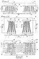
- a tapered SPUDT SAW filter device 10 is illustrated with reference to FIGS. 1 and 1A.
- the device 10 comprises input and output transducers 12, 14 with opposing bus bars 16, 18 each having a plurality of interdigitized, continuously tapered electrode fingers 20 configured in finger pairs 22 with each pair 22 having a finger of narrow width 24 adjacent to a finger with a larger or wider width 26 , by way of example in the embodiment illustrated.
- the finger widths 24, 26 are selected as a function of the impedance of a load 28 or source 30 so as to produce mechanical electrical loaded reflections in a substrate 32 upon which the transducers 12 , 14 are placed.
- a comparison between a conventional non-tapered 70 MHZ SPUDT filter with a 3 dB bandwidth of approximately 14.5 MHZ and a tapered SPUDT of the present invention having similar bandwidth and center frequency is made.
- an insertion loss 30 of the conventional filter is estimated at approximately 14 dB as measured from an amplitude frequency response 33 .
- the triple transit spurious signal 34 is suppressed approximately 34 dB below the main signal 35 as illustrated with reference to FIG. 3 for an amplitude time response 36 .
- the tapered SPUDT filter with similar bandwidth and center frequency exhibits an insertion loss 38 of about 12 dB and a triple transit suppression signal 40 greater than 42 dB as illustrated in the amplitude frequency response 42 and amplitude time response 44 respectively in FIGS. 4 and 5.
- a 2 dB improvement in the insertion loss ( 38 v. 30 ) along with greater than 8 dB improvement in the triple transit signal ( 40 v. 34 ) clearly demonstrates superior performance of the tapered SPUDT filter of the present invention over that of the conventional SPUDT filter.
- tapered transducer SAW filter device 50 illustrated with reference to FIG. 6.
- Tapered transducers are typically used in pairs, input transducer 54 and output transducer 56 in linear phase filter applications, each transducer having opposing bus bars 52, 53 .
- Surface wave propagation again with reference to FIG. 6, is from left to right as shown by the arrow 58 .
- the transverse dimension 60 is here defined as the X direction, and it can be seen that the period of the electrodes or fingers 62 (which defines the wavelength) becomes smaller as X increases. Consequently, the frequency increases with X.
- transducer tapered fingers 62 in one embodiment have the fingers 62 tapered along lines 64 which emanate from a single focal point 66 as is the embodiment of FIG. 1.
- the tapered fingers 20 follow hyperbolically curved lines 65 , as illustrated with reference to FIG. 1A.
- the high frequencies are detected in the upper portion 68 of the saw aperture, and the lower frequencies in the lower portion 70 of the SAW aperture.
- there are two electrodes per wavelength which, as earlier described, are typically solid electrodes. A variety of electrode structures may be used.
- every horizontal spacial interval or channel 72 of the transducers 52 should be essentially the same as all other slices 52 . In other words, all frequencies within the range of the device, though shifted up or down as the transducer 52 operates, will be excited (or detected) by the same electrode structure.
- apodization is not appropriate as a means of tap weighting.
- Other researchers have chosen to use apodization, with the result that the time response at different frequencies within the pass band is not the same.
- each horizontal slice or channel 72 as illustrated in FIG. 6 has a width ⁇ X which is sufficiently narrow so that the taper can be ignored.
- the spacing 63 between fingers 62 and the width 65 of the fingers 62 are dimensioned as fractional portions of a center frequency wavelength ⁇ as described in the Hunsinger '465 along any ⁇ X. In the analysis of the present invention, the taper can be ignored for that ⁇ X or channel 72 .
- the tapered electrode fingers 62 when the tapered electrode fingers 62 are divided into several channels parallel to the propagation direction 58 , they can be considered as normal ( i.e. , non-tapered) type fingers.
- the frequency response from the narrow slice 72 is that of a pair of unweighted transducers with 13 dB side lobes each, or 26 dB for the pair if they are identical.
- the response of any other channel 72 of width ⁇ X is the same but shifted up or down in frequency, depending upon its position in X along the transverse dimension 60 .
- the response of the entire filter 50 is the summation of all slices 72 that make up the aperture transverse dimension 60 .
- the response of a single channel is smeared over the frequency range from the lowest to the highest frequencies in the tapered electrodes. This produces a generally flat bandpass. If it is not sufficiently flat, it can be easily corrected to become flat by varying the rate of taper in the X direction. That can be understood by noting that, at any frequency (F i ), if the rate of taper (the slope of the lines 64 is reduced, with the result that the effective aperture at frequency F i is wider; and so the signal strength at F i is increased. Therefore, by selectively controlling the rate of taper in the transducer 52 , one can control the pass-band shape.
- the side lobes in the total response also result from smearing the side lobes of the narrow channel 72 or ⁇ X.
- the side lobes of a narrow channel are 26 dB, the resulting tapered filter will have side lobes which are of the order of 26 dB.
- the present invention combines SPUDT technology of narrow bandpass devices as earlier described with that of tapered wide band transducer technology.
- the problems associated with SAW devices requiring the use of wide bandwidths is resolved by the present invention which comprises SPUDT transducer geometries having tapered electrodes.
- the active portion of the transducer may be tens or hundreds of wavelengths long. Therefore, there is sufficient length in which to integrate the reflecting electrode structures with the transduction process and achieve the desired or necessary reflectivity.
- the bandwidth is achieved by tapering the electrodes over the desired frequency range. For a single channel 72 of the tapered filter 10 , the bandwidth is generally a few percent or less and the time impulse response generally has a simple response, like Hamming, in which there are no time phase side lobes.
- the auto convolution of this simple response is easy to implement within a narrow channel of the tapered transducer, and likewise for all other channels as it is continuously tapered.
- the time impulse response of the complete tapered transducer will be quite different as earlier described with reference to FIGS. 2 -5. It will have many time side lobes (the actual number depends upon the filter shape factor). The main lobe which accounts for most of the energy is only a fraction of the length of a single narrow channel. Since the reflection is canceled on a slice-by-slice, channel-by-channel or frequency-by-frequency basis, there is no need in a tapered transducer to confine the length of the reflectivity to such a narrow time response.
- the SPUDT conditions typically limited to narrow bandwidth conditions, can be met over any relative bandwidth with easily achievable reflectivities per tap.
- controlled tap weight strength and reflection strength is implemented on a tap by tap and finger-by-finger basis.
- the tap weight strength and reflection strength are controlled as illustrated, by way of example, with reference to FIG. 8 comprising a three-electrode per wavelength structure 80 .
- the upper bus bar 82 is assumed to be hot in the following discussion and comprises an electrode or finger 84 having a width w 2 .
- Fingers 86, 88 adjacent finger 84 are grounded and respectively are of width w 1 and w 3 .
- EWC Electrode Width Compensation
- the reflectivity and transduction strength of the structure 80 is to be varied.
- the EWC has a fixed tap weight strength and a fixed relative reflectivity of 2.0 (where the reflectivity from a single edge of an electrode is 1.0).
- the generalized three electrode or fingers 84, 86, 88 per wavelength structure 80 shall be called 3E/ ⁇ in these discussions.
- the transduction strength T is determined coarsely by setting the center finger 84 width w 2 .
- the remaining two-electrodes 86, 88 or more precisely, four-electrode edge positions 96, 98, 100, 102 are varied to define a specified or use specific (required) reflectivity.
- the phase of the reflection of a tap is referenced to the center of transduction, or roughly to the center of the center electrode or second finger 84 .
- the phase of the center finger 84 or second electrode is not changed, once selected, because its location or specifically width w 2 is specified by the transduction requirement.
- the combined reflection from all three electrodes or fingers 84, 86, 88 must satisfy the conditions that the component of the reflectivity in phase with the regeneration (centered roughly at electrode #2 84 ) must be of opposite sign or polarity as the regeneration reflection, and the component of the reflectivity in phase quadrature to the regeneration must be zero.
- the desired magnitude is specified by the filter design. These two conditions, plus the condition that no electrode or finger width or gap shall be smaller than some specified limit, are used to determine the edge of electrodes #1 86 and #3 88 , illustrated again with reference to FIG. 8. If necessary for a more accurate tap weight control, the actual transduction strength of the tap can be calculated knowing the locations of the nearest neighbors 86, 88 of electrode #2 84 .
- the width w 2 of electrode #2 84 can be increased or decreased to set the tap weight more precisely, and the corresponding reflectivity can be realized more precisely by adjusting the edge positions 96, 98, 100, 102 of the other two electrodes 86, 88 .
- This is an iterative process that converges very rapidly, and, in fact, for some applications one iteration is sufficient.
- the result is that for the 3E/ ⁇ structure 80 , one can independently specify the transduction strength T and the reflectivity R for each tap.
- the 3E/ ⁇ structure 80 is incorporated as illustrated with reference to FIG. 9 illustrating a transducer pattern which is replicated in a thin conductive film on the SAW device substrate.
- FIG. 10 a tapered SPUDT following the earlier described unbalanced split electrode geometry 81 is presented.
- the frequency sidelobes of the narrow channels determine the sidelobes in the tapered filter. What is needed is a method of weighting the taps, which is the same for all channels. In other words, weighting the electrodes within a given wavelength along the SAW path. Apodization does not meet the criteria.
- One technique which has been suggested in the prior art is withdrawal weighting. This will work and is an improvement over no weighting, but it is rather coarse and produces frequency sidelobes which increase in magnitude farther from the mainlobe. As a result, the selectivity will deteriorate for moderately to wideband filters as the mainlobe is smeared out to these increasing sidelobes.
- weighting There are three types of weighting that are used individually and in combination to provide improved frequency selectivity. They are series-block weighting, line-width weighting, and capacitive weighting. Series-block weighting and line-width weighting are herein described for preferred alternate embodiments of the present invention.
- the relative tap weight is proportional to the relative voltage applied to the tap.
- the three subtranducers 110, 112, 114 are acoustically cascaded (share the same acoustic track or device aperture 116 ) and are electrically in series. If the impedance is dominated by capacitance, which is generally the case, the impedance of each subtransducer is inversely proportional to the number of the taps within that subtransducer.
- An equivalent circuit of this string of subtransducers 110, 112, 114 is illustrated with reference to FIG. 12, where capacitors 118, 120, 122, respectively, have values z 1 , z 2 and z 3 . Again with reference to FIG.
- the outer bus bars 115 are called major bus bars.
- the taps within a substransducer all have the same weight and are a block of taps of the same strength.
- a string may consist of one subtransducer, in which case there is no voltage division and all taps in this string have a tap weight of unity.
- An advantage of block weighting is the uniformity of weighting across the SAW aperture and that it can be achieved with a single layer metalization.
- the disadvantages are that the taps cannot be individually weighted, and the possible tap weight values are somewhat limited (i) by the fact that the sum of the voltages across the subtransducers must be one, and (ii) by the constraints of setting the impedances by the number of taps. Nonetheless, block weighting provides a useful technique for use in the present invention.
- a second technique used to weight the taps includes varying the width of the electrodes, as earlier described. This is referred to as line-width weighting.
- line-width weighting Within a line-width frequency range, as the electrode or finger width 84, w 2 (refer to FIG. 8) (in the direction of SAW propagation) is increased, the tap weight or transduction strength of the tap is increased. This is valid for the range where w/ ⁇ (finger width to wavelength) is ⁇ .4, and for most practical examples where w/ ⁇ ⁇ .25.
- the lower range of w/ ⁇ is limited by the line width that can be fabricated both on the device and on the mask.
- this range of w/ ⁇ can be large enough to change the relative tap weight strength from 1.0 down to around 0.5, whereas at higher frequencies the frequency range will be much more limited. In general, it can be said that the range can not significantly approach zero and can only decrease somewhat from unity (relative tap weight).
- This line-width weighting is useful when combined with series-block weighting. Unlike line-width weighting techniques used in the past, limited because of limited tap weight range, when combined with series-block weighting, the achievable tap weight range is much broader.
- the line-width weighting of a 3E/ ⁇ structure 124 is used with series-block weighting to implement a Hamming weighted function (which is a common weighting function for each channel of a tapered transducer).
- a Hamming weighted function which is a common weighting function for each channel of a tapered transducer.
- the circuit 136 of the subtransducers (representing a transducer by a capacitor) is as shown in FIG. 14.
- the three subtransducers ( 130L-134R ) in series on each side of the center subtransducer 126 will divide the voltage between them by normal voltage division. If the number of electrodes or fingers in the subtransducer is n 1 , n 2 , n 3 and n 4 , as illustrated with reference to FIG.
- a plot 140 of the tap weight that can be realized by block weighting is illustrated with reference to FIG. 15. This is an approximation to a Hamming function.
- line-width weighting as herein described, we can reduce the tap weight of each tap within a block or subtransducer by a factor of m 1 where 1 ⁇ m 1 ⁇ 0.7 (the value of 0.7 is by way of example only).
- the combined series-block weighting and line-width weighting combination 142 is as illustrated with reference to FIG. 16.
- combined series-block and line-width weighting 142 provides an improved approximation to a desired tap weight function.
- frequency sidelobes will be correspondingly lower.
- the frequency response of the tapered transducer is derived from this non-tapered (narrow channel) response by "sliding" the non-tapered response over frequency channel by channel, as earlier described. A consequence of this process is that the better the selectivity of the narrow channel region, the better the selectivity of the tapered transducer.
- a tapered SPUDT transducer is configured with four electrodes per wavelength, as illustrated with reference to FIGS. 1 and 1A, and improved further with series-block weighting, as illustrated with reference to FIG. 13.
- An alternate embodiment describes a tapered three electrode per wavelength geometry, as illustrated with reference to FIG. 8, which in turn is coarsely weighted using series-block weighting techniques as herein described and finely weighted using line-width weighting techniques in combination with the block weighting.
Landscapes
- Physics & Mathematics (AREA)
- Acoustics & Sound (AREA)
- Surface Acoustic Wave Elements And Circuit Networks Thereof (AREA)
Claims (14)
- Wandler (12, 14) für eine akustische Oberflächenwellenvorrichtung (10), die ein eine akustische Welle propagierendes Substrat (32), auf das der Wandler adaptiert ist, beinhaltet, wobei der Wandler aufweist:ein Paar sich gegenüberstehende Leitungsschienen (16, 18), die auf einem Substrat angeordnet sind, wobei jede Leitungsschiene eine Vielzahl von sich hiervon ausstreckenden ineinandergreifenden Elektrodenfingern (22, 24, 26) besitzt, wobei die Breiten mindestens einiger Elektrodenfinger und die Abstände zwischen mindestens einigen Elektrodenfingern unterschiedlich sind und als eine Funktion der Impedanz einer zusammenwirkenden Last und/oder Quelle ausgewählt sind, um mechanische reflektierte akustische Wellen mit elektrischer Last in dem Substrat zu produzieren, um die regenerierten akustischen Wellen, die bei dem Wandler erzeugt wurden, im wesentlichen auszulöschen, wobei die ineinandergreifenden Elektrodenfinger weiterhin eine sich verjüngende bzw. keilförmige Elektrodenfingeranordnung haben, wobei eine regelmäßige Wiederkehr von Elektrodenfingern sich entlang einer Richtung im wesentlichen orthogonal zu einer akustischen Wellenpropagationsachse entlang des Wandlers ändert, undEinrichtungen (28, 30) für das Anlegen einer elektrischen Last und/oder Quelle zwischen den Leitungsschienen.
- Akustische Oberflächenwellenfiltervorrichtung (10), die über ein weites Frequenzband betriebsfähig ist und dafür vorgesehen ist, mit einer Quelle und/oder Last (28, 30) gekoppelt zu werden, wobei die Vorrichtung aufweist:ein eine akustische Welle propagierendes Substrat (32) mit einer akustischen Oberflächenwellen-Propagationsachse,mindestens einen akustischen Oberflächenwellenwandler (12, 14) mit einem Paar von gegenüberstehenden Leitungsschienen (16, 18), die auf dem Substrat gebildet sind, wobei jede Leitungsschiene eine Vielzahl von ineinandergreifenden Elektrodenfingern hat, die sich hiervon ausstrecken, wobei die Breite mindestens einiger Elektrodenfinger und die Abstände zwischen mindestens einigen Elektrodenfingern unterschiedlich sind und als eine Funktion der Impedanz einer zusammenwirkenden Last und/oder Quelle ausgewählt sind, um mechanische, reflektierte akustische Wellen mit elektrischer Last in dem Substrat zu erzeugen, um regenerierte akustische Wellen, die an dem Wandler erzeugt wurden, im wesentlichen auszulöschen, wobei die ineinandergreifenden Elektrodenfinger weiterhin eine sich verjüngende bzw. keilförmige Fingeranordnung haben, worin eine Periodizität bzw. Periodenlängen von Elektrodenfingern sich entlang einer im wesentlichen zu der Propagationsachse orthogonalen Richtung ändert, undEinrichtungen (28, 30) für das Anlegen einer elektrischen Last und/oder Quelle zwischen den Leitungsschienen.
- Wandler oder Vorrichtung nach Anspruch 1 oder 2, wobei die sich verjüngenden bzw. keilförmigen Elektrodenfinger zumindest einer Leitungsschiene eine Mehrzahl von Elektrodenfingerpaaren aufweisen, wobei jedes der Vielzahl von Elektrodenfingerpaaren einen Elektrodenfinger von schmaler Breite und einen benachbarten Elektrodenfinger von erhöhter Breite hat, wobei die Elektrodenfingerbreiten als Bruchteil einer akustischen Hauptfrequenz-wellenlänge der Vorrichtung dimensioniert sind.
- Wandler oder Vorrichtung nach Anspruch 1 oder 2, wobei der Abstand der Elektrodenfinger entlang der Propagationsachse innerhalb eines Längenmaßes, das gleich ihrer entsprechenden akustischen Wellenlänge ist, vier Elektrodenfinger bereitstellt.
- Wandler oder Vorrichtung nach Anspruch 1 oder 2, wobei mindestens eine Leitungsschiene innerhalb jeder akustischen Wellenlänge entlang der Propagationsachse zumindest zwei benachbarte Elektrodenfinger unterschiedlicher Breite besitzt, die sich hiervon erstrecken.
- Wandler oder Vorrichtung nach Anspruch 1 oder 2, wobei drei Elektrodenfinger über einen Zwischenraum einer akustischen Wellenlänge verteilt sind.
- Wandler oder Vorrichtung nach Anspruch 6, wobei Positionen und Breiten jeder der drei Elektrodenfinger ausgewählt sind, um unabhängig gewünschte Reflektions- und Wandlerstärken für jede Anzapfung innerhalb des Wandlers bereitzustellen.
- Wandler oder Vorrichtung nach Anspruch 4, wobei der erste und dritte Elektrodenfinger eine Breite von im wesentlichen 1/16 einer akustischen Wellenlänge und der zweite und vierte Elektrodenfinger eine Breite von im wesentlichen 3/16 der Wellenlänge besitzen, und benachbarte Elektrodenfinger durch eine Lücke von im wesentlichen 1/8 der Wellenlänge beabstandet sind.
- Wandler oder Vorrichtung nach Anspruch 1 oder 2, wobei die sich verjüngenden bzw. keilförmigen Finger im wesentlichen entlang sich radial erstreckenden Linienabschnitten angeordnet sind, die von einem gemeinsamen Brennpunkt ausgehen, um linear keilförmige Elektroden zu bilden.
- Wandler oder Vorrichtung nach Anspruch 1 oder 2, wobei die sich verjüngenden bzw. keilförmigen Finger im wesentlichen entlang gekrümmter Linienabschnitte angeordnet sind, um im wesentlichen sich hyperbolisch verjüngende Elektroden zu bilden.
- Wandler oder Vorrichtung nach Anspruch 1 oder 2, wobei eine Verjüngungsrate der Elektrodenfinger ausgewählt wird, um eine Bandpaßform zu steuern und das SAW-Gerät dazu zu bringen, innerhalb eines gewünschten Frequenzbereichs zu funktionieren.
- Wandler oder Vorrichtung nach Anspruch 1 oder 2, wobei der mindestens eine akustische Oberflächenwellenwandler eine Mehrzahl von Unterwandlern aufweist, wobei jeder der Vielzahl der Unterwandlern Elektrodenfinger hat, die mit Elektrodenfingem von sich gegenüberstehenden Unterwandlernleitungsschienen ineinandergreifen, wobei eine Anzahl von Anzapfungen in jeder der Vielzahl von Unterwandlern variiert, die Vielzahl von Unterwandlern elektrisch verbunden sind, um eine Serienblockgewichtung der sich verjüngenden bzw. keilförmigen Wandler bereitzustellen.
- Wandler oder Vorrichtung nach Anspruch 12, wobei weiterhin die Vielzahl von Unterwandlern symmetrisch auf jeder Seite eines ineinandergreifenden Wandlerfingersatzes positioniert sind.
- Wandler oder Vorrichtung nach Anspruch 12, der weiterhin einen im Zentrum angeordneten Satz von ineinandergreifenden Wandlerelektrodenfingem aufweist und wobei die Vielzahl von Unterwandlern auf jeder Seite des Wandlerelektrodenfingersatzes angeordnet sind.
Applications Claiming Priority (3)
| Application Number | Priority Date | Filing Date | Title |
|---|---|---|---|
| US08/529,238 US5831492A (en) | 1995-09-15 | 1995-09-15 | Weighted tapered spudt saw device |
| US529238 | 1995-09-15 | ||
| PCT/US1995/016528 WO1997010646A1 (en) | 1995-09-15 | 1995-12-18 | Weighted tapered spudt saw device |
Publications (2)
| Publication Number | Publication Date |
|---|---|
| EP0850510A1 EP0850510A1 (de) | 1998-07-01 |
| EP0850510B1 true EP0850510B1 (de) | 2000-03-22 |
Family
ID=24109090
Family Applications (1)
| Application Number | Title | Priority Date | Filing Date |
|---|---|---|---|
| EP95944832A Revoked EP0850510B1 (de) | 1995-09-15 | 1995-12-18 | Gewichtete keilförmige spudt-saw-vorrichtung |
Country Status (7)
| Country | Link |
|---|---|
| US (1) | US5831492A (de) |
| EP (1) | EP0850510B1 (de) |
| JP (1) | JPH11500593A (de) |
| KR (1) | KR100301781B1 (de) |
| AU (1) | AU5521996A (de) |
| DE (1) | DE69515917T2 (de) |
| WO (1) | WO1997010646A1 (de) |
Cited By (1)
| Publication number | Priority date | Publication date | Assignee | Title |
|---|---|---|---|---|
| DE102005009359B4 (de) * | 2005-03-01 | 2014-12-11 | Epcos Ag | Bandpassfilter |
Families Citing this family (42)
| Publication number | Priority date | Publication date | Assignee | Title |
|---|---|---|---|---|
| US5663695A (en) * | 1994-10-31 | 1997-09-02 | Ngk Insulators, Ltd. | Surface acoustic wave filter device and transducer therefor |
| US6031315A (en) * | 1997-07-16 | 2000-02-29 | Sawtek Inc. | Optimal cut for saw devices on quartz |
| JP2000036722A (ja) * | 1998-05-11 | 2000-02-02 | Tdk Corp | 弾性表面波装置の設計方法および弾性表面波装置 |
| JPH11330895A (ja) * | 1998-05-14 | 1999-11-30 | Fujitsu Ltd | 弾性表面波装置 |
| US7037268B1 (en) * | 1999-03-01 | 2006-05-02 | Medacoustics, Inc. | Low profile acoustic sensor arry and sensors with pleated transmission lines and related methods |
| EP1156891B1 (de) * | 1999-03-01 | 2005-11-30 | MedAcoustics, Inc. | Akustische sensoranordnung mit niedrigen profil und sensoren mit gefaltenen übertragungsleitungen und entsprechendes verfahren |
| US6239422B1 (en) * | 1999-03-10 | 2001-05-29 | Trw Inc. | Variable electrode traveling wave metal-semiconductor-metal waveguide photodetector |
| US6023122A (en) * | 1999-04-15 | 2000-02-08 | Nortel Networks Corporation | Surface wave devices with tapered transducers |
| DE19925800C1 (de) * | 1999-06-03 | 2000-12-21 | Dresden Ev Inst Festkoerper | Wandler für akustische Oberflächenwellen |
| US6707229B1 (en) * | 1999-06-03 | 2004-03-16 | Tele Filter Zweigniederlassung Der Dover Germany Gmbh | Surface acoustic wave filter |
| DE19944452B4 (de) * | 1999-09-16 | 2004-05-06 | Advalytix Ag | Vorrichtung und Verfahren zum Ermitteln des Ortes der Wechselwirkung einer akustischen Oberflächenwelle |
| US6462698B2 (en) * | 2000-06-02 | 2002-10-08 | Research In Motion Limited | Wireless communication system using surface acoustic wave (SAW) single-phase unidirectional transducer (SPUDT) techniques |
| US6380828B1 (en) | 2000-07-24 | 2002-04-30 | Nortel Networks Limited | Surface wave devices with static electric field |
| JP3414373B2 (ja) | 2000-07-26 | 2003-06-09 | 株式会社村田製作所 | 弾性表面波装置 |
| US6791236B1 (en) | 2000-10-11 | 2004-09-14 | Yuri Abramov | Method utilizing the saw velocity dispersion effect for weighting by shaping the electrode fingers of a saw interdigital transducer and apparatus produced thereby |
| US6469598B2 (en) * | 2001-03-12 | 2002-10-22 | Matsushita Electric Industrial Co., Ltd. | SAW filter with unidirectional transducer and communication apparatus using the same |
| DE10113788A1 (de) * | 2001-03-21 | 2002-09-26 | Zeiss Carl | Beugungsoptische Komponente, Beleuchtungssystem und Belichtungssystem mit einer solchen beugungsoptischen Komponente und Belichtungsverfahren unter Verwendung eines solchen Belichtungssystems |
| JP3780415B2 (ja) * | 2001-06-12 | 2006-05-31 | 株式会社村田製作所 | 縦結合共振子型弾性表面波フィルタ、およびそれを用いた通信機装置 |
| US6559739B2 (en) | 2001-10-05 | 2003-05-06 | Sawtek, Inc. | String weighted surface acoustic wave transducer |
| DE10314153A1 (de) | 2003-03-28 | 2004-10-07 | Epcos Ag | Oberflächenwellen-Anordnung zur breitbandigen Signalübertragung |
| DE10345239B4 (de) * | 2003-09-29 | 2013-09-05 | Epcos Ag | Mit Oberflächenwellen arbeitender Wandler |
| JP2005150918A (ja) * | 2003-11-12 | 2005-06-09 | Murata Mfg Co Ltd | 弾性表面波フィルタ |
| US10008083B2 (en) * | 2004-10-19 | 2018-06-26 | Solybyung Coveley | Passive tamper-resistant seal and applications therefor |
| US7576471B1 (en) | 2007-09-28 | 2009-08-18 | Triquint Semiconductor, Inc. | SAW filter operable in a piston mode |
| JP5042763B2 (ja) * | 2007-09-28 | 2012-10-03 | 日本電波工業株式会社 | 弾性波フィルタ |
| EP2104229B1 (de) | 2008-03-17 | 2011-09-14 | Epcos AG | SAW Transversalfilter |
| US7821360B2 (en) * | 2008-08-28 | 2010-10-26 | Northrop Grumman Systems Corporation | Multi-channel surface acoustic wave filter device with voltage controlled tunable frequency response |
| JP4694609B2 (ja) * | 2008-10-24 | 2011-06-08 | 日本電波工業株式会社 | 弾性波フィルタ |
| AU2010246904B2 (en) * | 2009-05-11 | 2015-08-20 | Monash University | Microfluidic apparatus for the atomisation of a liquid |
| JP5760321B2 (ja) * | 2009-07-07 | 2015-08-05 | 日本電波工業株式会社 | 弾性波フィルタ |
| JP5365406B2 (ja) * | 2009-08-11 | 2013-12-11 | 日本電波工業株式会社 | 弾性波フィルタ |
| JP5581859B2 (ja) * | 2009-09-04 | 2014-09-03 | 日本電波工業株式会社 | 弾性波フィルタ |
| JP2011211414A (ja) * | 2010-03-29 | 2011-10-20 | Nippon Dempa Kogyo Co Ltd | 弾性波フィルタ |
| WO2012103958A1 (en) * | 2011-02-04 | 2012-08-09 | Epcos Ag | Broadband saw filter |
| JP5898908B2 (ja) * | 2011-10-11 | 2016-04-06 | 日本電波工業株式会社 | 弾性波フィルタ |
| DE102013204428B4 (de) * | 2012-03-29 | 2014-08-07 | Leibniz-Institut Für Festkörper- Und Werkstoffforschung Dresden E.V. | Akustisches Oberflächenwellenbauelement |
| US9170686B2 (en) * | 2013-01-10 | 2015-10-27 | Elo Touch Solutions, Inc. | Multi-transducer waveguide arrays |
| JP2014192866A (ja) * | 2013-03-28 | 2014-10-06 | Nippon Dempa Kogyo Co Ltd | 弾性波フィルタ |
| JP6274929B2 (ja) * | 2014-03-18 | 2018-02-07 | 日本電波工業株式会社 | 弾性波フィルタ |
| WO2015155984A1 (en) * | 2014-04-08 | 2015-10-15 | Skyworks Panasonic Filter Solutions Japan Co., Ltd. | Acoustic wave resonators, acoustic wave filters, antenna duplexers, modules and communication devices using the same |
| CN112953457A (zh) * | 2021-02-26 | 2021-06-11 | 深圳市中讯声表研究中心有限公司 | 一种分节加权声表面波换能器 |
| TWI860794B (zh) * | 2023-07-26 | 2024-11-01 | 欣興電子股份有限公司 | 電容元件、包含其的線路載板及其製作方法 |
Family Cites Families (28)
| Publication number | Priority date | Publication date | Assignee | Title |
|---|---|---|---|---|
| US3870975A (en) * | 1974-03-22 | 1975-03-11 | Hazeltine Corp | Surface wave transducer with reduced reflection coefficient |
| JPS54844A (en) * | 1977-06-03 | 1979-01-06 | Matsushita Electric Ind Co Ltd | Elastic surface wave filter |
| US4114116A (en) * | 1977-08-01 | 1978-09-12 | United Technologies Corporation | Two-dimensional surface acoustic wave signal processor |
| US4162465A (en) * | 1977-09-14 | 1979-07-24 | University Of Illinois Foundation | Surface acoustic wave device with reflection suppression |
| JPS5610724A (en) * | 1979-07-09 | 1981-02-03 | Toshiba Corp | Elastic surface wave transducer |
| US4316161A (en) * | 1979-07-10 | 1982-02-16 | Westinghouse Electric Corp. | Wideband low triple transit delay line |
| US4321696A (en) * | 1980-02-12 | 1982-03-23 | Hitachi, Ltd. | Ultrasonic transducer using ultra high frequency |
| US4331840A (en) * | 1980-02-22 | 1982-05-25 | Lectret S.A. | Electret transducer with tapered acoustic chamber |
| US4348904A (en) * | 1980-08-08 | 1982-09-14 | North American Philips Corporation | Acoustic impedance matching device |
| JPS57145419A (en) * | 1981-03-05 | 1982-09-08 | Clarion Co Ltd | Surface acoustic wave element |
| US4480209A (en) * | 1981-10-09 | 1984-10-30 | Clarion Co., Ltd. | Surface acoustic wave device having a specified crystalline orientation |
| GB2120890B (en) * | 1982-04-19 | 1985-11-27 | Philips Electronic Associated | Acoustic surface wave device |
| US4625184A (en) * | 1982-07-02 | 1986-11-25 | Clarion Co., Ltd. | Surface acoustic wave device with impedance matching network formed thereon |
| JPS5964908A (ja) * | 1982-10-05 | 1984-04-13 | Nobuo Mikoshiba | 弾性表面波素子 |
| JPS60117907A (ja) * | 1983-11-30 | 1985-06-25 | Hitachi Ltd | 弾性表面波フィルタ |
| JPS60180316A (ja) * | 1984-02-28 | 1985-09-14 | Japan Radio Co Ltd | 弾性表面波フイルタ |
| JPS61220509A (ja) * | 1985-03-27 | 1986-09-30 | Hitachi Ltd | 弾性表面波装置 |
| US4600905A (en) * | 1985-09-03 | 1986-07-15 | The United States Of America As Represented By The Secretary Of The Army | Flat passband etched groove saw filter |
| US4635008A (en) * | 1985-11-19 | 1987-01-06 | Sperry Corporation | Dispersive SAW filter with tapered transducers |
| US4672592A (en) * | 1985-12-23 | 1987-06-09 | Westinghouse Electric Corp. | Shaded transducer |
| JPS63294009A (ja) * | 1987-05-26 | 1988-11-30 | Clarion Co Ltd | 弾性表面波装置 |
| US4749971A (en) * | 1987-06-24 | 1988-06-07 | Unisys Corporation | Saw delay line with multiple reflective taps |
| US4908542A (en) * | 1987-06-24 | 1990-03-13 | Unisys | Saw tapered transducers |
| US4746882A (en) * | 1987-06-24 | 1988-05-24 | Unisys Corporation | Saw multiplexer using tapered transducers |
| US4767198A (en) * | 1987-06-24 | 1988-08-30 | Unisys Corporation | SAW/BAW Bragg cell |
| JP2606708B2 (ja) * | 1987-11-17 | 1997-05-07 | 日本無線株式会社 | 弾性表面波フィルタ |
| JPH0217707A (ja) * | 1988-07-05 | 1990-01-22 | Clarion Co Ltd | 広帯域弾性表面波フィルタ |
| US5289073A (en) * | 1992-11-09 | 1994-02-22 | The United States Of America As Represented By The Secretary Of The Army | Unidirectional surface acoustic wave transducer |
-
1995
- 1995-09-15 US US08/529,238 patent/US5831492A/en not_active Expired - Lifetime
- 1995-12-18 WO PCT/US1995/016528 patent/WO1997010646A1/en not_active Ceased
- 1995-12-18 AU AU55219/96A patent/AU5521996A/en not_active Abandoned
- 1995-12-18 JP JP9511909A patent/JPH11500593A/ja active Pending
- 1995-12-18 DE DE69515917T patent/DE69515917T2/de not_active Expired - Fee Related
- 1995-12-18 KR KR1019980701940A patent/KR100301781B1/ko not_active Expired - Fee Related
- 1995-12-18 EP EP95944832A patent/EP0850510B1/de not_active Revoked
Cited By (1)
| Publication number | Priority date | Publication date | Assignee | Title |
|---|---|---|---|---|
| DE102005009359B4 (de) * | 2005-03-01 | 2014-12-11 | Epcos Ag | Bandpassfilter |
Also Published As
| Publication number | Publication date |
|---|---|
| DE69515917T2 (de) | 2000-10-05 |
| EP0850510A1 (de) | 1998-07-01 |
| AU5521996A (en) | 1997-04-01 |
| WO1997010646A1 (en) | 1997-03-20 |
| KR19990044685A (ko) | 1999-06-25 |
| KR100301781B1 (ko) | 2001-09-06 |
| US5831492A (en) | 1998-11-03 |
| DE69515917D1 (de) | 2000-04-27 |
| JPH11500593A (ja) | 1999-01-12 |
Similar Documents
| Publication | Publication Date | Title |
|---|---|---|
| EP0850510B1 (de) | Gewichtete keilförmige spudt-saw-vorrichtung | |
| EP0184508B1 (de) | Wandler für akustische Oberflächenwellen | |
| US6791236B1 (en) | Method utilizing the saw velocity dispersion effect for weighting by shaping the electrode fingers of a saw interdigital transducer and apparatus produced thereby | |
| US5646584A (en) | Saw filter including electrodes of opposing polarity | |
| US7023300B2 (en) | Surface wave devices with low passband ripple | |
| US4281301A (en) | Acoustic wave devices | |
| US4908542A (en) | Saw tapered transducers | |
| EP0483940B1 (de) | Einphasiger, einseitig gerichteter, gruppenförmig angeordneter Wandler mit 3/8 Lambda und 5/8 Lambda Bemusterung | |
| JPS62120115A (ja) | テ−パ変換器を有する分散形表面音響波フイルタ | |
| US3894251A (en) | Elastic surface wave transducer | |
| US6051908A (en) | Reduced coupling saw filter | |
| EP0599475B1 (de) | Akustische Oberflächenwellenanordnung zur Erzeugung einer akustischen Ausgangssignalwelle mit nur einer symmetrischen oder nur einer assymmetrischen Schwingungsform | |
| EP0840446B1 (de) | Unidirektionales Filter mit akustischen Oberflächenwellen | |
| US5818310A (en) | Series-block and line-width weighted saw filter device | |
| US5670920A (en) | Multi-track SAW filter with reflectors and reversed polarity IDT connections | |
| EP0106384B1 (de) | Akustische Oberflächenwellenanordnung | |
| US4333065A (en) | Low reflectivity apodized surface acoustic transducer with means to prevent wavefront distortion | |
| EP0197640B1 (de) | Akustische Oberflächenwellenanordnungen mit Fingern zur Unterdrückung von Reflexionen | |
| US4365220A (en) | Surface wave circuit device | |
| JPS63215108A (ja) | 表面弾性波装置 | |
| US4205285A (en) | Acoustic surface wave device | |
| EP0255263A2 (de) | Wandler | |
| US6559739B2 (en) | String weighted surface acoustic wave transducer | |
| US5327039A (en) | Weighting transducer for surface acoustic wave filter | |
| EP0153092A2 (de) | Bandpassfilter für akustische Oberflächenwellen |
Legal Events
| Date | Code | Title | Description |
|---|---|---|---|
| PUAI | Public reference made under article 153(3) epc to a published international application that has entered the european phase |
Free format text: ORIGINAL CODE: 0009012 |
|
| 17P | Request for examination filed |
Effective date: 19980414 |
|
| AK | Designated contracting states |
Kind code of ref document: A1 Designated state(s): DE FR |
|
| GRAG | Despatch of communication of intention to grant |
Free format text: ORIGINAL CODE: EPIDOS AGRA |
|
| 17Q | First examination report despatched |
Effective date: 19990504 |
|
| GRAG | Despatch of communication of intention to grant |
Free format text: ORIGINAL CODE: EPIDOS AGRA |
|
| GRAH | Despatch of communication of intention to grant a patent |
Free format text: ORIGINAL CODE: EPIDOS IGRA |
|
| GRAH | Despatch of communication of intention to grant a patent |
Free format text: ORIGINAL CODE: EPIDOS IGRA |
|
| GRAA | (expected) grant |
Free format text: ORIGINAL CODE: 0009210 |
|
| AK | Designated contracting states |
Kind code of ref document: B1 Designated state(s): DE FR |
|
| REF | Corresponds to: |
Ref document number: 69515917 Country of ref document: DE Date of ref document: 20000427 |
|
| ET | Fr: translation filed | ||
| PGFP | Annual fee paid to national office [announced via postgrant information from national office to epo] |
Ref country code: FR Payment date: 20001124 Year of fee payment: 6 |
|
| PLBQ | Unpublished change to opponent data |
Free format text: ORIGINAL CODE: EPIDOS OPPO |
|
| PLBI | Opposition filed |
Free format text: ORIGINAL CODE: 0009260 |
|
| PGFP | Annual fee paid to national office [announced via postgrant information from national office to epo] |
Ref country code: DE Payment date: 20010125 Year of fee payment: 6 |
|
| 26 | Opposition filed |
Opponent name: EPCOS AG Effective date: 20001222 |
|
| PLBF | Reply of patent proprietor to notice(s) of opposition |
Free format text: ORIGINAL CODE: EPIDOS OBSO |
|
| RDAH | Patent revoked |
Free format text: ORIGINAL CODE: EPIDOS REVO |
|
| REG | Reference to a national code |
Ref country code: FR Ref legal event code: ST |
|
| RDAG | Patent revoked |
Free format text: ORIGINAL CODE: 0009271 |
|
| STAA | Information on the status of an ep patent application or granted ep patent |
Free format text: STATUS: PATENT REVOKED |
|
| 27W | Patent revoked |
Effective date: 20020531 |