EP0850872A1 - Device for rapidly mounting/releasing capping heads for caps or lids - Google Patents
Device for rapidly mounting/releasing capping heads for caps or lids Download PDFInfo
- Publication number
- EP0850872A1 EP0850872A1 EP97204021A EP97204021A EP0850872A1 EP 0850872 A1 EP0850872 A1 EP 0850872A1 EP 97204021 A EP97204021 A EP 97204021A EP 97204021 A EP97204021 A EP 97204021A EP 0850872 A1 EP0850872 A1 EP 0850872A1
- Authority
- EP
- European Patent Office
- Prior art keywords
- bush
- bell
- piece
- tube
- designed
- Prior art date
- Legal status (The legal status is an assumption and is not a legal conclusion. Google has not performed a legal analysis and makes no representation as to the accuracy of the status listed.)
- Granted
Links
- 239000012530 fluid Substances 0.000 claims abstract description 3
- 238000007789 sealing Methods 0.000 description 2
- 238000000605 extraction Methods 0.000 description 1
- 238000003780 insertion Methods 0.000 description 1
- 230000037431 insertion Effects 0.000 description 1
- 238000004519 manufacturing process Methods 0.000 description 1
- 238000002360 preparation method Methods 0.000 description 1
- 230000000717 retained effect Effects 0.000 description 1
Images

Classifications
-
- B—PERFORMING OPERATIONS; TRANSPORTING
- B67—OPENING, CLOSING OR CLEANING BOTTLES, JARS OR SIMILAR CONTAINERS; LIQUID HANDLING
- B67B—APPLYING CLOSURE MEMBERS TO BOTTLES JARS, OR SIMILAR CONTAINERS; OPENING CLOSED CONTAINERS
- B67B3/00—Closing bottles, jars or similar containers by applying caps
-
- B—PERFORMING OPERATIONS; TRANSPORTING
- B67—OPENING, CLOSING OR CLEANING BOTTLES, JARS OR SIMILAR CONTAINERS; LIQUID HANDLING
- B67B—APPLYING CLOSURE MEMBERS TO BOTTLES JARS, OR SIMILAR CONTAINERS; OPENING CLOSED CONTAINERS
- B67B2201/00—Indexing codes relating to constructional features of closing machines
- B67B2201/10—Quick or easy connection means for connecting a capping head to a spindle
Definitions
- the present invention relates to a device for rapidly mounting/releasing units for fitting caps or lids to containers, in particular for mandrels of automatic machines.
- the technical problem which is posed, therefore, is that of providing a device for rapidly attaching cap or lid fitting units for mandrels of automatic container sealing machines, which allows rapid and easy changing of the said unit in safe conditions and with the machine at a standstill, allowing the downtime of the processing cycle to be reduced.
- said device should be easy and inexpensive to manufacture and should be adaptable to machines of the known type without the need for additional parts and/or complicated connecting elements.
- a device for rapidly mounting/releasing units for fitting caps or lids to containers in particular for mandrels of automatic machines, which comprises at least one tube which is fixed to the mandrel and on which there are coaxially mounted at least one bell-piece integral with said tube and at least one bush partially sealingly inserted in said bell-piece, so as to form a chamber, and designed to translate coaxially with said bell-piece under the thrusting action of resilient means and a fluid under pressure which can be supplied, upon command, to said chamber, there also being provided means for fixing the unit to said bush, which means extend radially from said unit and are designed to cooperate with a shaped eyelet formed on the side surface of the bush.
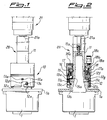
- the device 10 for the rapid engagement of cap or lid fitting units 1 to mandrels 20 of filling machines which are known per se and only schematically shown with the actuator 21 for moving the said mandrel 20, comprises a tube 11 which is fixed to an axial extension 21a of the actuator 21 by means of screws 11a and which has, at its end opposite to the free end, a circular flange 11b provided with a radial toothing 11c designed to form the guide for sliding, in the axial direction, of a bush 12 which is provided with corresponding internal longitudinal grooves 12b and coaxially mounted over the tube 11.
- the external side surface of said bush 12 has, formed in it, a hole 12a and a shaped eyelet 12c respectively designed to allow insertion, through them, of a grub screw 13a for fixing the bush 12 to the flange 11b of the tube 11, and a screw 13b with a cylindrical head 13c which is screwed onto a support element 1a of the unit 1.
- the shaped eyelet 12c has a horizontal section 12d with an axial recess 12e designed to contain partially the head 13c of the screw 13b.
- the bush 12 In its cylindrical upper part the bush 12 has seats 15a, each of which houses a ball 15 and a spring 16 located above said ball.
- the spring 16 is normally compressed, in a direction parallel to the axis of the mandrel, between said ball 15 and a disc 17 for upper closing of the bush 12, which is fixed to the latter by means of screws 17a.
- the said disc 17 is in turn inserted inside a cylindrical bell-piece 18 which is coaxial with the tube 12 and fixed to the latter by means of radial pins 18'a; in this way the bell-piece 18 forms a cylinder, the piston of which consists in the assembly formed by the disc 17/bush 12 which can be moved in an axial direction and against the thrusting action of the springs 16, by means of compressed air supplied to the chamber 18a via a duct 18b formed on the bell-piece 18 and connected to the compressed-air source by means of a connecting nozzle 18c.
- the travel of said disc/bush assembly is determined by two surfaces, i.e. an external surface 12f and internal surface 12g of the bush itself, which are perpendicular to the longitudinal axis and form an end-of-travel stop for the bush 12 against the flange 11b of the tube 11 and against the edge of the bell-piece 18, respectively.
- the device for rapid engagement/disengagement of the cap or lid fitting unit operates in the following manner:
- the head 13c of the screw 13b is inserted into the axial recess 12e and the unit 1 is firmly retained in the delivery position.
- the head 13c of the screw 13b is disengaged from the associated recess 12e of the eyelet 12c and the unit 1 is able to be rotated in an anti-clockwise direction (Figs. 4a,4b) and translated downwards for extraction thereof.
Landscapes
- Engineering & Computer Science (AREA)
- Mechanical Engineering (AREA)
- Sealing Of Jars (AREA)
- Closing Of Containers (AREA)
- Manipulator (AREA)
- Automatic Assembly (AREA)
Abstract
Description
- Under normal working conditions (Figs. 1, 2) the
upper part 1a of theunit 1 is in abutment against theflange 11b of thefixed tube 12 and the body of the mandrel is rotated in an anti-clockwise direction so as to bring thehead 13c of the screw 13b inside therecess 12e of theshaped eyelet 12c.
- If the
unit 1 is to be replaced, compressed air is supplied to thechamber 18a through theduct spring 15 and push downwards thetube 11, which stops with its internal abutment surface 12g against theflange 11b of the tube.
- In order to insert a new unit, the sequence is performed in reverse.
Claims (9)
- Device for rapidly mounting/releasing units (1,1a) for fitting caps or lids to containers, in particular for mandrels (20) of automatic machines (21,21a), characterized in that it comprises at least one tube (11) which is fixed to the mandrel (20) and on which there are coaxially mounted at least one bell-piece (18) integral with said tube (11) and at least one bush (12,17) partially sealingly inserted in said bell-piece (18), so as to form a chamber (18a), and designed to translate coaxially with said bell-piece under the thrusting action of resilient means (16) and a fluid under pressure which can be supplied, upon command, to said chamber (18a), there being also provided means (13,13a) for fixing the unit (1,1a) to said bush (12), which means extend radially from said unit (1a,1) and are designed to co-operate with a shaped eyelet (12c,12e) formed on the side surface of the bush (12).
- Device according to Claim 1, characterized in that the tube has a free end shaped in the manner of a flange (11b) provided with a radial toothing (11c).
- Device according to Claim 1, characterized in that said bush (12) has a body substantially formed by two coaxial cylinders of different diameter.
- Device according to Claim 1, characterized in that at least one of said cylinders forming the bush (12) has an internal surface with axial grooves (12b) designed to form guides for sliding of the bush on said toothing (11b) of the tube (11).
- Device according to Claim 1, characterized in that the other of said two cylinders forming the bush (12) has, formed in it, seats (15a) for containing resilient elements (15) acting between a cover (17) fixed to the bush (12) and said flange of the fixed tube (11).
- Device according to Claim 1, characterized in that said bell-piece (18) is provided with through-ducts (18b) for communication with said chamber (18a) between bell-piece (18) and bush (12).
- Device according to Claim 1, characterized in that said radial means for fixing the unit (1) to the bush (12) consist of a screw (13b) with a cylindrical head (13c).
- Device according to Claims 1 and 6, characterized in that said cylindrical head (13c) has a diameter smaller than the widthwise dimensions of the said recess (12c,12d).
- Device according to Claim 1, characterized in that said shaped eyelet (12c,12d) of the bush (12) has an axial groove (12e) designed to contain partially the head (13c) of said screw (13b).
Applications Claiming Priority (2)
| Application Number | Priority Date | Filing Date | Title |
|---|---|---|---|
| ITMI962729 | 1996-12-23 | ||
| IT96MI002729A IT1289514B1 (en) | 1996-12-23 | 1996-12-23 | QUICK COUPLING DEVICE FOR APPLICATION GROUPS OF CAPS TO CONTAINERS, ESPECIALLY FOR AUTOMATIC MACHINE SPINDLES |
Publications (2)
| Publication Number | Publication Date |
|---|---|
| EP0850872A1 true EP0850872A1 (en) | 1998-07-01 |
| EP0850872B1 EP0850872B1 (en) | 2000-03-01 |
Family
ID=11375480
Family Applications (1)
| Application Number | Title | Priority Date | Filing Date |
|---|---|---|---|
| EP97204021A Expired - Lifetime EP0850872B1 (en) | 1996-12-23 | 1997-12-19 | Device for rapidly mounting/releasing capping heads for caps or lids |
Country Status (5)
| Country | Link |
|---|---|
| US (1) | US5884450A (en) |
| EP (1) | EP0850872B1 (en) |
| DE (1) | DE69701348T2 (en) |
| ES (1) | ES2142652T3 (en) |
| IT (1) | IT1289514B1 (en) |
Cited By (7)
| Publication number | Priority date | Publication date | Assignee | Title |
|---|---|---|---|---|
| GB2332195A (en) * | 1997-12-15 | 1999-06-16 | Bosch Gmbh Robert | Quick change coupling for a closuring head |
| EP1245525A1 (en) | 2001-03-30 | 2002-10-02 | RONCHI MARIO S.p A. | Device for rapid engagement/release of units for fitting lids to containers |
| EP1273551A1 (en) * | 2001-07-05 | 2003-01-08 | MBF S.p.A. | Capping head for a capping machine |
| EP1864941A1 (en) * | 2006-06-07 | 2007-12-12 | Obrist Closures Switzerland GmbH | Quick release capping head |
| EP2279849A3 (en) * | 2009-07-31 | 2014-05-07 | Krones AG | Quick swap mechanism for base parts |
| WO2018072900A1 (en) * | 2016-10-19 | 2018-04-26 | Krones Ag | Quick-change coupling for a container treatment machine |
| US20250145442A1 (en) * | 2016-03-22 | 2025-05-08 | M&M Machinery Services, Inc. | Vent tube for bottling machine and related methods |
Families Citing this family (17)
| Publication number | Priority date | Publication date | Assignee | Title |
|---|---|---|---|---|
| US6170232B1 (en) * | 1997-12-30 | 2001-01-09 | Vandegeijn Peter T. | Quick-change collet chuck |
| US6250046B1 (en) * | 1998-05-01 | 2001-06-26 | Vandegeijn Peter T. | Collet crimping head |
| FR2810657B1 (en) * | 2000-06-21 | 2002-09-06 | Serac Group | TIGHTENING SPINDLE PROVIDED WITH A DISMOUNTABLE GRIPPER. |
| ITTO20030229A1 (en) * | 2003-03-27 | 2004-09-28 | Arol Spa | CAPSULATING HEAD FOR THE VACUUM APPLICATION OF CAPSULES |
| US6945011B2 (en) * | 2003-05-29 | 2005-09-20 | Blackhawk Molding Co., Inc. | Container closure system |
| US7182918B2 (en) * | 2004-03-11 | 2007-02-27 | Conoco Phillips Company | Desulfurization process |
| US7343720B2 (en) * | 2005-10-04 | 2008-03-18 | Adcor Industries, Inc. | Capping device with quick release mechanism and methods of releasing and re-connecting |
| US7661245B2 (en) * | 2005-10-04 | 2010-02-16 | Adcor Industries, Inc. | Capping device with bearing mechanism having a plurality of bearing members between a drive member and a capper body |
| US7963500B1 (en) * | 2006-12-06 | 2011-06-21 | Holiday Angela C | Snowman mold |
| DE102007014812A1 (en) * | 2007-03-28 | 2008-10-02 | Dr. Datz Getränke- und Sondermaschinenfabrikation GmbH | Container fixture e.g. label and neck foil, removing device, has fastener for removable separating agent and unit for centering container, where separating agent is designed as snatching bolt and/or as separating pin |
| DE102007028429A1 (en) * | 2007-06-20 | 2008-12-24 | Krones Ag | Device for closing containers with screw caps |
| DE102010048720A1 (en) * | 2010-10-19 | 2012-04-19 | Krones Aktiengesellschaft | Quick-mount bottom mold with switchable holding force support |
| EP2882677B1 (en) * | 2012-08-07 | 2018-12-26 | Cedrex A/S | Test tube capping and de-capping apparatus and method |
| DE102013103111A1 (en) * | 2013-03-26 | 2014-10-02 | George Robert Collins | Holder for a container receptacle and container receptacle |
| DE202013011928U1 (en) * | 2013-12-18 | 2014-10-30 | Newfrey Llc | Removable die and joining tool |
| IT201800009973A1 (en) * | 2018-10-31 | 2020-05-01 | Mbf Spa | MOTORCYCLE TRANSMISSION UNIT FOR CAPPING HEADS FOR SCREW CAPS AND CAPPING MACHINE EQUIPPED WITH THIS MOTORCYCLE TRANSMISSION GROUP |
| DE202021104818U1 (en) | 2021-09-07 | 2021-09-15 | Krones Aktiengesellschaft | Coupling system for coupling a closure head for closing a container with a container closure to a closure device, closure device and closure head |
Citations (4)
| Publication number | Priority date | Publication date | Assignee | Title |
|---|---|---|---|---|
| US4527377A (en) * | 1982-07-06 | 1985-07-09 | Mitsubishi Jukogyo Kabushiki Kaisha | Washing device in a container sealing apparatus |
| EP0572107A1 (en) * | 1992-05-29 | 1993-12-01 | Shibuya Kogyo Co., Ltd | A work head changer for a rotary vessel processing system |
| GB2268165A (en) * | 1992-06-30 | 1994-01-05 | United Distillers Plc | Adapting capping apparatus for applying different closures |
| US5417031A (en) * | 1993-08-26 | 1995-05-23 | New England Machinery, Inc. | Apparatus for rotating cylindrical caps onto containers |
Family Cites Families (5)
| Publication number | Priority date | Publication date | Assignee | Title |
|---|---|---|---|---|
| US3524294A (en) * | 1967-10-20 | 1970-08-18 | American Flange & Mfg | Bottle capping equipment and method |
| US3491516A (en) * | 1967-10-25 | 1970-01-27 | Pneumatic Scale Corp | Closure applying apparatus |
| US3955341A (en) * | 1975-10-14 | 1976-05-11 | Horix Manufacturing Company | Apparatus for screwing caps on containers |
| GB1596355A (en) * | 1978-03-22 | 1981-08-26 | Metal Closures Group Ltd | Capping machinery |
| DE2846846C2 (en) * | 1978-10-27 | 1982-05-27 | Rationator-Maschinenbau Gmbh, 6521 Hillesheim | Pliers head on a sealing machine |
-
1996
- 1996-12-23 IT IT96MI002729A patent/IT1289514B1/en active IP Right Grant
-
1997
- 1997-12-19 EP EP97204021A patent/EP0850872B1/en not_active Expired - Lifetime
- 1997-12-19 DE DE69701348T patent/DE69701348T2/en not_active Expired - Fee Related
- 1997-12-19 ES ES97204021T patent/ES2142652T3/en not_active Expired - Lifetime
- 1997-12-22 US US08/996,333 patent/US5884450A/en not_active Expired - Lifetime
Patent Citations (4)
| Publication number | Priority date | Publication date | Assignee | Title |
|---|---|---|---|---|
| US4527377A (en) * | 1982-07-06 | 1985-07-09 | Mitsubishi Jukogyo Kabushiki Kaisha | Washing device in a container sealing apparatus |
| EP0572107A1 (en) * | 1992-05-29 | 1993-12-01 | Shibuya Kogyo Co., Ltd | A work head changer for a rotary vessel processing system |
| GB2268165A (en) * | 1992-06-30 | 1994-01-05 | United Distillers Plc | Adapting capping apparatus for applying different closures |
| US5417031A (en) * | 1993-08-26 | 1995-05-23 | New England Machinery, Inc. | Apparatus for rotating cylindrical caps onto containers |
Cited By (11)
| Publication number | Priority date | Publication date | Assignee | Title |
|---|---|---|---|---|
| GB2332195A (en) * | 1997-12-15 | 1999-06-16 | Bosch Gmbh Robert | Quick change coupling for a closuring head |
| GB2332195B (en) * | 1997-12-15 | 2000-01-12 | Bosch Gmbh Robert | Quick-change device for a closure head on a container handling station |
| EP1245525A1 (en) | 2001-03-30 | 2002-10-02 | RONCHI MARIO S.p A. | Device for rapid engagement/release of units for fitting lids to containers |
| US6840024B2 (en) | 2001-03-30 | 2005-01-11 | Ronchi Mario S.P.A. | Device for rapid engagement/release of units for fitting lids to containers |
| EP1273551A1 (en) * | 2001-07-05 | 2003-01-08 | MBF S.p.A. | Capping head for a capping machine |
| EP1864941A1 (en) * | 2006-06-07 | 2007-12-12 | Obrist Closures Switzerland GmbH | Quick release capping head |
| WO2007141144A1 (en) * | 2006-06-07 | 2007-12-13 | Obrist Closures Switzerland Gmbh | Quick-change screw head |
| EP2279849A3 (en) * | 2009-07-31 | 2014-05-07 | Krones AG | Quick swap mechanism for base parts |
| US20250145442A1 (en) * | 2016-03-22 | 2025-05-08 | M&M Machinery Services, Inc. | Vent tube for bottling machine and related methods |
| WO2018072900A1 (en) * | 2016-10-19 | 2018-04-26 | Krones Ag | Quick-change coupling for a container treatment machine |
| US11192766B2 (en) | 2016-10-19 | 2021-12-07 | Krones Ag | Quick-change coupling for a container treatment machine |
Also Published As
| Publication number | Publication date |
|---|---|
| ITMI962729A1 (en) | 1998-06-23 |
| US5884450A (en) | 1999-03-23 |
| IT1289514B1 (en) | 1998-10-15 |
| EP0850872B1 (en) | 2000-03-01 |
| ES2142652T3 (en) | 2000-04-16 |
| DE69701348T2 (en) | 2000-07-06 |
| DE69701348D1 (en) | 2000-04-06 |
Similar Documents
| Publication | Publication Date | Title |
|---|---|---|
| EP0850872B1 (en) | Device for rapidly mounting/releasing capping heads for caps or lids | |
| CN110589732B (en) | Closure head for closing a container by means of a container closure | |
| US4044462A (en) | Rivet blank feeder for riveting apparatus | |
| EP0443362B1 (en) | Cutter disc arbor particularly for dividing machines | |
| EP0570005A2 (en) | Spin flow necking apparatus and method of handling cans therein | |
| EP2794145B1 (en) | Grip device for locking cylindrical metallic bodies to be machined by means of machine tools | |
| US6840024B2 (en) | Device for rapid engagement/release of units for fitting lids to containers | |
| JP2020097446A (en) | Power transmission group for capping heads for screw caps, and capping apparatus comprising the same | |
| JP4369126B2 (en) | Cigarette packing machine | |
| RU2422287C2 (en) | Clamping holder for digital printing on can body | |
| EP1273551B1 (en) | Capping machine with a capping head | |
| CA1105904A (en) | Bottle capping apparatus and method | |
| US20100299906A1 (en) | Apparatus and method of forming the brake actuator | |
| US7810620B2 (en) | Bracket mounting structure and bracket mounting method | |
| HU209715B (en) | Indirect extrusion apparatus | |
| GB1596355A (en) | Capping machinery | |
| US2662679A (en) | Bottle hooding and capping mechanism | |
| US5167266A (en) | Apparatus for filling containers with liquid | |
| JP5003206B2 (en) | Plug direction control device | |
| US5685220A (en) | Apparatus for printing on flat individual articles | |
| CA1066897A (en) | Safety lock for forming machine blowhead | |
| US6062278A (en) | Machine for filling containers provided with automatic devices for rapidly locking/releasing the interchangeable elements guiding and moving the containers themselves | |
| JPH055612B2 (en) | ||
| CN219363209U (en) | Coupling system for coupling a capping head for capping a container with the container to a capping device, capping device and capping head | |
| CN117865037A (en) | Sealing head for sealing machine |
Legal Events
| Date | Code | Title | Description |
|---|---|---|---|
| PUAI | Public reference made under article 153(3) epc to a published international application that has entered the european phase |
Free format text: ORIGINAL CODE: 0009012 |
|
| AK | Designated contracting states |
Kind code of ref document: A1 Designated state(s): DE ES FR GB IT |
|
| AX | Request for extension of the european patent |
Free format text: AL;LT;LV;MK;RO;SI |
|
| 17P | Request for examination filed |
Effective date: 19981224 |
|
| AKX | Designation fees paid |
Free format text: DE ES FR GB IT |
|
| RBV | Designated contracting states (corrected) |
Designated state(s): DE ES FR GB IT |
|
| GRAG | Despatch of communication of intention to grant |
Free format text: ORIGINAL CODE: EPIDOS AGRA |
|
| 17Q | First examination report despatched |
Effective date: 19990427 |
|
| GRAG | Despatch of communication of intention to grant |
Free format text: ORIGINAL CODE: EPIDOS AGRA |
|
| GRAH | Despatch of communication of intention to grant a patent |
Free format text: ORIGINAL CODE: EPIDOS IGRA |
|
| GRAH | Despatch of communication of intention to grant a patent |
Free format text: ORIGINAL CODE: EPIDOS IGRA |
|
| GRAA | (expected) grant |
Free format text: ORIGINAL CODE: 0009210 |
|
| AK | Designated contracting states |
Kind code of ref document: B1 Designated state(s): DE ES FR GB IT |
|
| ET | Fr: translation filed | ||
| REF | Corresponds to: |
Ref document number: 69701348 Country of ref document: DE Date of ref document: 20000406 |
|
| REG | Reference to a national code |
Ref country code: ES Ref legal event code: FG2A Ref document number: 2142652 Country of ref document: ES Kind code of ref document: T3 |
|
| ITF | It: translation for a ep patent filed | ||
| PLBE | No opposition filed within time limit |
Free format text: ORIGINAL CODE: 0009261 |
|
| STAA | Information on the status of an ep patent application or granted ep patent |
Free format text: STATUS: NO OPPOSITION FILED WITHIN TIME LIMIT |
|
| 26N | No opposition filed | ||
| REG | Reference to a national code |
Ref country code: GB Ref legal event code: IF02 |
|
| REG | Reference to a national code |
Ref country code: ES Ref legal event code: PC2A |
|
| REG | Reference to a national code |
Ref country code: FR Ref legal event code: CJ |
|
| PGFP | Annual fee paid to national office [announced via postgrant information from national office to epo] |
Ref country code: ES Payment date: 20081204 Year of fee payment: 12 |
|
| PGFP | Annual fee paid to national office [announced via postgrant information from national office to epo] |
Ref country code: IT Payment date: 20081223 Year of fee payment: 12 |
|
| PGFP | Annual fee paid to national office [announced via postgrant information from national office to epo] |
Ref country code: DE Payment date: 20090226 Year of fee payment: 12 |
|
| PGFP | Annual fee paid to national office [announced via postgrant information from national office to epo] |
Ref country code: GB Payment date: 20081218 Year of fee payment: 12 |
|
| PGFP | Annual fee paid to national office [announced via postgrant information from national office to epo] |
Ref country code: FR Payment date: 20081223 Year of fee payment: 12 |
|
| GBPC | Gb: european patent ceased through non-payment of renewal fee |
Effective date: 20091219 |
|
| REG | Reference to a national code |
Ref country code: FR Ref legal event code: ST Effective date: 20100831 |
|
| PG25 | Lapsed in a contracting state [announced via postgrant information from national office to epo] |
Ref country code: FR Free format text: LAPSE BECAUSE OF NON-PAYMENT OF DUE FEES Effective date: 20091231 |
|
| PG25 | Lapsed in a contracting state [announced via postgrant information from national office to epo] |
Ref country code: DE Free format text: LAPSE BECAUSE OF NON-PAYMENT OF DUE FEES Effective date: 20100701 |
|
| PG25 | Lapsed in a contracting state [announced via postgrant information from national office to epo] |
Ref country code: GB Free format text: LAPSE BECAUSE OF NON-PAYMENT OF DUE FEES Effective date: 20091219 |
|
| PG25 | Lapsed in a contracting state [announced via postgrant information from national office to epo] |
Ref country code: IT Free format text: LAPSE BECAUSE OF NON-PAYMENT OF DUE FEES Effective date: 20091219 |
|
| REG | Reference to a national code |
Ref country code: ES Ref legal event code: FD2A Effective date: 20110405 |
|
| PG25 | Lapsed in a contracting state [announced via postgrant information from national office to epo] |
Ref country code: ES Free format text: LAPSE BECAUSE OF NON-PAYMENT OF DUE FEES Effective date: 20110323 |
|
| PG25 | Lapsed in a contracting state [announced via postgrant information from national office to epo] |
Ref country code: ES Free format text: LAPSE BECAUSE OF NON-PAYMENT OF DUE FEES Effective date: 20091220 |