EP0851079A1 - Schliesszylinder - Google Patents
Schliesszylinder Download PDFInfo
- Publication number
- EP0851079A1 EP0851079A1 EP97110457A EP97110457A EP0851079A1 EP 0851079 A1 EP0851079 A1 EP 0851079A1 EP 97110457 A EP97110457 A EP 97110457A EP 97110457 A EP97110457 A EP 97110457A EP 0851079 A1 EP0851079 A1 EP 0851079A1
- Authority
- EP
- European Patent Office
- Prior art keywords
- key
- core
- tumbler
- cylinder
- housing
- Prior art date
- Legal status (The legal status is an assumption and is not a legal conclusion. Google has not performed a legal analysis and makes no representation as to the accuracy of the status listed.)
- Granted
Links
- 238000003780 insertion Methods 0.000 claims description 19
- 230000037431 insertion Effects 0.000 claims description 19
- 230000006835 compression Effects 0.000 claims description 15
- 238000007906 compression Methods 0.000 claims description 15
- 238000007654 immersion Methods 0.000 claims description 9
- 230000008901 benefit Effects 0.000 claims description 5
- 230000001681 protective effect Effects 0.000 claims description 4
- 238000011144 upstream manufacturing Methods 0.000 claims description 4
- 230000002441 reversible effect Effects 0.000 claims description 3
- 210000001061 forehead Anatomy 0.000 claims 1
- 230000000903 blocking effect Effects 0.000 description 3
- 238000000034 method Methods 0.000 description 3
- 230000008569 process Effects 0.000 description 3
- 235000014676 Phragmites communis Nutrition 0.000 description 2
- 241001295925 Gegenes Species 0.000 description 1
- 230000009471 action Effects 0.000 description 1
- 230000001154 acute effect Effects 0.000 description 1
- 230000008859 change Effects 0.000 description 1
- 238000006243 chemical reaction Methods 0.000 description 1
- 238000013461 design Methods 0.000 description 1
- 238000006073 displacement reaction Methods 0.000 description 1
- 230000000694 effects Effects 0.000 description 1
- 238000005516 engineering process Methods 0.000 description 1
- 230000001771 impaired effect Effects 0.000 description 1
- 230000003993 interaction Effects 0.000 description 1
- 230000001105 regulatory effect Effects 0.000 description 1
- 238000012549 training Methods 0.000 description 1
- 238000012546 transfer Methods 0.000 description 1
Images


Classifications
-
- E—FIXED CONSTRUCTIONS
- E05—LOCKS; KEYS; WINDOW OR DOOR FITTINGS; SAFES
- E05B—LOCKS; ACCESSORIES THEREFOR; HANDCUFFS
- E05B27/00—Cylinder locks or other locks with tumbler pins or balls that are set by pushing the key in
- E05B27/0003—Details
- E05B27/0017—Tumblers or pins
- E05B27/0021—Tumblers or pins having movable parts
-
- E—FIXED CONSTRUCTIONS
- E05—LOCKS; KEYS; WINDOW OR DOOR FITTINGS; SAFES
- E05B—LOCKS; ACCESSORIES THEREFOR; HANDCUFFS
- E05B19/00—Keys; Accessories therefor
- E05B19/0017—Key profiles
-
- E—FIXED CONSTRUCTIONS
- E05—LOCKS; KEYS; WINDOW OR DOOR FITTINGS; SAFES
- E05B—LOCKS; ACCESSORIES THEREFOR; HANDCUFFS
- E05B27/00—Cylinder locks or other locks with tumbler pins or balls that are set by pushing the key in
- E05B27/0042—Cylinder locks or other locks with tumbler pins or balls that are set by pushing the key in with additional key identifying function, e.g. with use of additional key operated rotor-blocking elements, not of split pin tumbler type
-
- E—FIXED CONSTRUCTIONS
- E05—LOCKS; KEYS; WINDOW OR DOOR FITTINGS; SAFES
- E05B—LOCKS; ACCESSORIES THEREFOR; HANDCUFFS
- E05B27/00—Cylinder locks or other locks with tumbler pins or balls that are set by pushing the key in
- E05B27/0057—Cylinder locks or other locks with tumbler pins or balls that are set by pushing the key in with increased picking resistance
- E05B27/006—Cylinder locks or other locks with tumbler pins or balls that are set by pushing the key in with increased picking resistance whereby a small rotation without the correct key blocks further rotation of the rotor
- E05B27/0064—Cylinder locks or other locks with tumbler pins or balls that are set by pushing the key in with increased picking resistance whereby a small rotation without the correct key blocks further rotation of the rotor whereby the rotor is irreversibly blocked or can only be moved back with an authorized tool or key
-
- E—FIXED CONSTRUCTIONS
- E05—LOCKS; KEYS; WINDOW OR DOOR FITTINGS; SAFES
- E05B—LOCKS; ACCESSORIES THEREFOR; HANDCUFFS
- E05B27/00—Cylinder locks or other locks with tumbler pins or balls that are set by pushing the key in
- E05B27/0078—Asymmetrical tumbler pins, e.g. with a key operating on a radial protrusion of a tumbler pin
-
- E—FIXED CONSTRUCTIONS
- E05—LOCKS; KEYS; WINDOW OR DOOR FITTINGS; SAFES
- E05B—LOCKS; ACCESSORIES THEREFOR; HANDCUFFS
- E05B19/00—Keys; Accessories therefor
- E05B19/0017—Key profiles
- E05B19/0041—Key profiles characterized by the cross-section of the key blade in a plane perpendicular to the longitudinal axis of the key
- E05B19/0052—Rectangular flat keys
-
- E—FIXED CONSTRUCTIONS
- E05—LOCKS; KEYS; WINDOW OR DOOR FITTINGS; SAFES
- E05B—LOCKS; ACCESSORIES THEREFOR; HANDCUFFS
- E05B15/00—Other details of locks; Parts for engagement by bolts of fastening devices
- E05B15/04—Spring arrangements in locks
- E05B2015/0448—Units of springs; Two or more springs working together
-
- Y—GENERAL TAGGING OF NEW TECHNOLOGICAL DEVELOPMENTS; GENERAL TAGGING OF CROSS-SECTIONAL TECHNOLOGIES SPANNING OVER SEVERAL SECTIONS OF THE IPC; TECHNICAL SUBJECTS COVERED BY FORMER USPC CROSS-REFERENCE ART COLLECTIONS [XRACs] AND DIGESTS
- Y10—TECHNICAL SUBJECTS COVERED BY FORMER USPC
- Y10T—TECHNICAL SUBJECTS COVERED BY FORMER US CLASSIFICATION
- Y10T70/00—Locks
- Y10T70/70—Operating mechanism
- Y10T70/7441—Key
- Y10T70/7486—Single key
- Y10T70/7508—Tumbler type
- Y10T70/7559—Cylinder type
- Y10T70/7565—Plural tumbler sets
-
- Y—GENERAL TAGGING OF NEW TECHNOLOGICAL DEVELOPMENTS; GENERAL TAGGING OF CROSS-SECTIONAL TECHNOLOGIES SPANNING OVER SEVERAL SECTIONS OF THE IPC; TECHNICAL SUBJECTS COVERED BY FORMER USPC CROSS-REFERENCE ART COLLECTIONS [XRACs] AND DIGESTS
- Y10—TECHNICAL SUBJECTS COVERED BY FORMER USPC
- Y10T—TECHNICAL SUBJECTS COVERED BY FORMER US CLASSIFICATION
- Y10T70/00—Locks
- Y10T70/70—Operating mechanism
- Y10T70/7441—Key
- Y10T70/7486—Single key
- Y10T70/7508—Tumbler type
- Y10T70/7559—Cylinder type
- Y10T70/7588—Rotary plug
- Y10T70/7593—Sliding tumblers
- Y10T70/7599—Transverse of plug
- Y10T70/7605—Pin tumblers
-
- Y—GENERAL TAGGING OF NEW TECHNOLOGICAL DEVELOPMENTS; GENERAL TAGGING OF CROSS-SECTIONAL TECHNOLOGIES SPANNING OVER SEVERAL SECTIONS OF THE IPC; TECHNICAL SUBJECTS COVERED BY FORMER USPC CROSS-REFERENCE ART COLLECTIONS [XRACs] AND DIGESTS
- Y10—TECHNICAL SUBJECTS COVERED BY FORMER USPC
- Y10T—TECHNICAL SUBJECTS COVERED BY FORMER US CLASSIFICATION
- Y10T70/00—Locks
- Y10T70/70—Operating mechanism
- Y10T70/7441—Key
- Y10T70/778—Operating elements
- Y10T70/7791—Keys
- Y10T70/7842—Single shank or stem
- Y10T70/7859—Flat rigid
- Y10T70/7864—Cylinder lock type
Definitions
- the invention relates to a lock cylinder with a Cylinder housing, the core bore a key channel having cylinder core, with in Cylinder core arranged core pins and in housing pin bores slidably guided, by means of springs spring-loaded housing pins in the direction of the core pins and with at least one of broadside profiling of the key in the rotary joint of the cylinder body intersecting cavity displaceable core-side additional tumbler element, which is in the core outward direction is spring loaded and which one from the side control protrusion protruding into the key channel owns.
- a lock cylinder of the type in question is known from GB 112 761, the additional tumbler element has a tubular section the outside thereof in the extension of the pipe section a hook-shaped section is attached.
- the longer one The hook leg runs parallel to the key channel and carries a spring designed as a compression spring, which is the additional tumbler element in the core outward direction spring loaded into a stop position.
- the shorter one approximately at right angles to the longer hook leg running hook leg, however, represents the Control tab represents which in the key channel protrudes.
- the tumblers are arranged using the Keychain incised locking notches while the shifting of the tumbler element by means of a key-wide longitudinal groove takes place.
- the object of the invention is based on the object a lock cylinder of the type in question in technically simple way of increased Specify security value.
- One version is characterized by that the tumbler pin from a housing-side seated in the locking recess Tumbler element is formed. Becomes a key used, the broadside profiling is not on the additional tumbler element and the housing side Conversion pin is matched, the lock occurs after inserting the key.
- The also has a manufacturing-facilitating effect From the fact that the cylinder core Housing section a plugged into a cylinder opening Hollow cylinder, which is the housing side Cavity section is assigned, the bottom of which Cylinder wall is formed.
- the core side The key that forms the tumbler element stands out characterized in that the key profiling from a Side wall of a longitudinal rib or groove is formed.
- the core-side tumbler element to be classify the tumbler elements according to regulations can.
- the longitudinal rib is the key edge adjacent.
- the trouble-free insertion of the key is in the key channel due to the fact ensures that the key tip is slanted tapered side wall section to form a Insertion funnel is used.
- the key also as a flat reversible key to train. Even if you insert the key the key is tilted into the key channel nevertheless the key can be inserted because that the key shaft in the area of its key tip Roof slopes arranged to each other in a roof shape forms, which open into the longitudinal groove bottom.
- Aggravating has a copyability as well as a scanability characterized in that the tip area of the key shaft has its greatest thickness at the edge. So that is that controls the tumbler element at the core Longitudinal wall below the key broadside what leads to the aforementioned advantage.
- Another version is characterized in that the tumbler pin that can be immersed in the core cavity by a partial rotation of the cylinder core into the immersion position bringable and from one of the core pens assigned housing pin is formed.
- This housing pin works with the core pin assigned to it.
- a key abuse is thereby recognizable.
- the axial position of the tumbler element is axial offset to the housing pin holes such that the cross-sectional areas of the tumbler and housing side Overlap tumbler pin.
- the tumbler bearing Cavity section merges into an immersion space for the relevant tumbler pin on the housing side continues.
- the floor plan of this immersion room is adapted the relevant pin on the housing, so that if you use the wrong key, which the tumbler element is too deep in the core cavity pulls in, enter into the immersion space can block the closing rotation of the cylinder core.
- a sufficiently large overlap between Immersion space and tumbler element is achieved that the tumbler element in cross section is designed trapezoidal in such a way that the trapezoidal base opposite trapezoidal side the control lead trains.
- a hiding place of the tumbler element is achieved in that it is in the inner end region of the Cylinder core is arranged and thus when withdrawn Key from the core pins in front of it
- the protected arrangement is optimal by a control projection in the key insertion direction upstream, a broadside recess of the key scanning protective pin. Is the key the protective pin prevents it from being inserted with certainty access to the control protrusion of the tumbler element. Then only the key can be inserted be the corresponding broadside recess owns. If this is not available, the Do not insert the key at all.
- the master key forming a rib, which at the end of the insert a control slope for the tax advantage and subordinate to this a control recess, the rib of the single key ends blunt to the direction of insertion and otherwise has a constant cross-sectional contour.
- the insert the single key in the parent Lock cylinder can therefore due to the lack of Tax slants of the individual keys the additional guard locking not to relocate, but only bumps into them and prevents further insertion of the key.
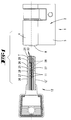
- FIGS. 1 to 10 has the trained as a profile half cylinder Lock cylinder 1 a cylinder housing 2, which itself from a cylinder opening 3, in cross section circular cylinder wall 4 and one of this radially uniform outgoing web section 5 composed.
- a housing section 6 representing hollow cylinder inserted and by means of one not shown, from the web section 5 outgoing grub screw fixed.
- the one as a hollow cylinder designed housing section 6 forms with its inner wall a core bore 7 into which a cylinder core 8 is inserted.
- a radially cut Key channel 9 incorporated to the one side of the rotary joint F of the cylinder core 8 down is open and with the longitudinal median plane of the web section 5 is aligned.
- the cylinder core takes 8 two-part tumbler pins 10 by key shaft-wide recesses 11 a Key 12 are classified. The core side Ends of those sprung towards the key channel Tumbler pins 10 protrude into the Key channel 9 into it.
- Such tumblers are however known, so that it is not discussed in detail becomes.
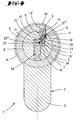
- the housing-side locking recess 13 takes one in Spring-loaded housing pin on, which is designed as a tumbler element 14 and with a core-side cushioned in the outward direction of the housing Tumbler element 15 interacts.
- the latter has an approximately central cross-sectional constriction 16 in the form of a stepped pin, which of the as Compression spring trained spring 17 is included.
- the one Spring associated with the housing-side tumbler element 14 18 is also designed as a compression spring and supports from the cylinder wall 4. It is such a dimensioning the springs 17,18 made that the spring force the core-side spring 17 is larger than that the housing-side spring 18. This ensures that the housing-side tumbler element 14 always the displacement of the core tumbler element 15 follows.
- Tumbler elements 14, 15 Due to the extra-diametrical arrangement of the Tumbler elements 14, 15 have cavity H one non-circular cross-section, in which cavity H the tumbler elements 14,15 insert positively and rotatably.
- the end face contour is S or the parting line between the two tumbler elements 14, 15 of the rotary joint contour customized.
- the core cavity 13 takes the constriction 16 form-fitting leading shoe 19, on one of which The compression spring 17 is supported.
- the core tumbler element 15 is in two parts designed. One part 15 'forms the constriction 16 and the other part 15 '' the end face. In connection on the shoulder 21 is part 15 'in the Key channel 9 protruding control projection 22 formed.
- the assembly of the core-side, divided tumbler element 15 happens in such a way that initially the part 15 'with its pin-like constriction 16 passes through a bore 23 of the shoe 19. After that the compression spring 17 and then the part 15 '' pressed the end portion of the constriction 16 so that the two parts 15 ', 15' 'act as one part. Then the core tumbler 15 with the shoe inserted into the core cavity 13. This is dimensioned that an inward shift of the core-side part 15 'is possible.
- the corresponding one Free space is designated there with the number 24. It would be possible to achieve a one-piece tumbler element 15 to arrange the compression spring 18 in this free space 24, however, this is not shown.
- the key profiling cooperating with the control projection 22 is of a side wall 25 one Longitudinal rib 26 or - groove 27 formed. To this end is the side wall 25 with at least one control recess 28 equipped, which, in the longitudinal direction of the key seen, roof slopes to each other roof-shaped 29 are assigned. In the example are three such tax recesses 28 in a row provided so that the lock cylinder 1 a corresponding number of tumbler elements arranged in pairs 14.15.
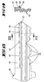
- the longitudinal rib 26 is the key narrow edge 30 adjacent. In the area of the key tip sets the side wall 25 into a part of an insertion funnel T-training, sloping on the tip side outgoing side wall section 25 '.
- The, in Cross-section seen, diametrically opposite longitudinal rib 25 is also designed accordingly, so that the key 12 also serves as a flat reversible key.
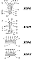
- FIGS. 5, 6 and 7 has the one that follows the 12 '' key Key shaft 12 'in the insertion side Tip area a cross-sectional other rib structure than the area of the key shaft 12 'close to the tide.
- a cross-sectional other rib structure than the area of the key shaft 12 'close to the tide.
- the ribs 33 are in Key shaft longitudinal ribs 33 that opposite in longitudinal ribs 26 set back by dimension x lie. Because of this, a detachability becomes It is difficult to copy the key.
- the ribs 33 however, end in the area in front of the first depressions 11 of the key shaft 12 'or tangent to it.
- Corresponding the key channel also has this rib structure 9 of the cylinder core 8 in the end region appropriate cross-sectional profiling. To this through Ribs 33 generated cross-sectional profile closes that of the area close to the reed so that the Arranging the folding pins 10 is not impaired is.
- a closing rotation of the cylinder core 8 requires this Insert the regulatory key 12 into the Key channel 9.
- both the tumbler pins 10 and the tumbler elements 14.15 arranged, whereby the turning of the Cylinder core is made possible.
- This is seen in the tumbler elements 14.15 so that of the concerned Side wall 25 with the control recesses located therein 28 the control projections 22 accordingly shifted will.
- the core Tumbler element 15 pulled in the core inward direction.
- the spring-loaded tumbler element follows this shift 14. In the fully retracted position then aligns the end face contour S between the two tumbler elements 14, 15 with that of Revolving joint F of the cylinder core 8, so that the closing rotation of the cylinder core can be made.
- Figure 4 illustrates an incorrect key 34. Its side wall 25 '' is designed so that it the core tumbler element 15 is shifted so far, that the end face contour S of both tumbler elements 14.15 has exceeded the cylinder core rotary joint F and is located within the cylinder core 8. Thereby is a rotation of the cylinder core 8 by the housing side Tumbler element 14 prevents itself in the case of correctly arranged tumbler pins 10 a rotational movement of the cylinder core 8 is blocked.
- Embodiment is also a Profile half cylinder trained locking cylinder 35.
- Its cylinder section 36 takes in the Kerhbohrung 7 rotatably a cylinder core 8 ', while the web portion 37 for housing housing pin holes 38 is used. In these lead from compression springs 39 acted upon housing pins 40. These act together with core pins guided in core pin bores 41 42.
- a key channel extends at the level of the cylinder core 8 ' 43 to accommodate a correspondingly profiled Shaft 44 of a key 45.
- Its key chest is equipped with locking notches 46, which are the core pins 42 so that the parting line between the Core pins 42 and the housing pins 40 at the level of Revolving joint F of the cylinder core 8 'lies.
- the rotary joint runs parallel to the key channel 43 F crossing cavity H '. This is composed from the core cavity open to the key channel 43 47 and the housing-side locking recess 48.
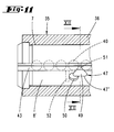
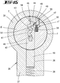
- the core cavity 47 has a tumbler element 49 leading cavity section 47 ', which continues into an immersion space 50 on the mouth side. The latter extends in the plane of rotation one of the adjacent tumbler pins 40, see this in particular Figure 11. That of a spring 58 in the core outward direction Actuated tumbler element 49 is roughly trapezoidal in cross-section.
- the the Trapezoidal base opposite trapezoidal side forms the in the control projection 51 protruding into the key channel 43 out. As illustrated in FIG. 11, the Control tab 51 on gap between two neighboring Tumbler pin pairs and thus also the tumbler element 49.
- FIG. 11 illustrates that the axial Position of the tumbler 49 is axially offset to the housing pin bores 38 so that the cross-sectional areas of the tumbler element 49 and the housing side Overlap tumbler pin 40. Then FIG. 11 illustrates that the tumbler element 49 arranged in the inner end region of the cylinder core 8 ' is.
- Control projection 51 upstream protective pin 52 provided.
- the latter gropes a broadside cutout 53 a longitudinal rib 54 located on the key shaft 44 from. If the broadside recess 53 is missing on the key shaft, so this can not be inserted.
- the broadside protrusion 53 is in the direction of the key tip seen, a cut in the longitudinal rib 54 Tax well 55 upstream, which is over sloping sections into the side wall 56 of the longitudinal rib 54 continues.
- the side wall 56 is a control slope 57 assigned.
- the operation of the lock cylinder 35 according to the second embodiment is as follows: When the key is not inserted into the key channel 43 45 there is a rotation lock of the cylinder core 8 ' both by the housing pins 40 and by that Tumbler element 49, which exceeds the rotary joint F. and engages in the locking recess 48.
- a closing rotation of the cylinder core 8 'requires this Insert the correct key 45 which can be a master key in the exemplary embodiment.
- the housing pins 40 and core pins 42 arranged so that their parting line to lie at the level of the rotary joint F of the cylinder core 8 ' is coming.
- the Control slopes 57 and the control projection 51 the tumbler 49 withdrawn.
- the control element 51 is then supported on the control recess 55 from such that that of the cylinder core curvature following face of the tumbler 49 lies at the level of the rotary joint F.
- the cylinder core 8 'can thus be rotated by means of the key 45 will.
- FIG. is largely identical to key 45.
- this false key 59 lacks the tax rate 57 on the longitudinal rib 54. This means that the Longitudinal rib 54 ends bluntly to the direction of insertion. At the attempted insertion of this key 59 encounters this blunt end 60 of the longitudinal rib 54 against the control projection 51 blocking another Insert this key 59.
- a key 61 is illustrated, whose longitudinal rib 54 is also blunt to the direction of insertion ends and otherwise a constant cross-sectional contour owns.
- This key 61 could in Framework of a master key system as a single key to serve. He is therefore unable to control the superordinate one Actuate lock cylinder, which is the tumbler element 49 owns. In contrast, he can in the subordinate Lock cylinders are inserted and there the core and Arrange housing pins.
- One manufactures on this Key 61, as illustrated in phantom in Figure 17 is a tax slope 60, so can this key 61 completely into the key channel insert. It then also arranges the core pins 42 and Housing pins 40 properly.
Landscapes
- Lock And Its Accessories (AREA)
- Vehicle Body Suspensions (AREA)
- Chairs Characterized By Structure (AREA)
- Valve Device For Special Equipments (AREA)
- Amplifiers (AREA)
- Surgical Instruments (AREA)
- Selective Calling Equipment (AREA)
- Fluid-Damping Devices (AREA)
- Pens And Brushes (AREA)
- Fastening Of Light Sources Or Lamp Holders (AREA)
- Mobile Radio Communication Systems (AREA)
- Adornments (AREA)
Abstract
Description
- Fig. 1
- eine Ansicht einer erfindungsgemäß gestalteten Schließvorrichtung in vergrößerter Darstellung, welche Schließvorrichtung sich aus einem Schlüssel und einem als Profil-Halbzylinder ausgebildeten Schließzylinder zusammensetzt, betreffend die erste Ausführungsform,
- Fig. 2
- einen Querschnitt durch den Schließzylinder im Bereich einer die Zuhaltungselemente aufnehmenden Höhlung,
- Fig. 3
- eine der Figur 2 entsprechende Darstellung, wobei der zugehörige Schlüssel eingesteckt ist unter Einordnen der Zuhaltungselemente,
- Fig. 4
- ebenfalls ein der Figur 2 entsprechender derschnitt, wobei ein falscher Schlüssel eingesteckt ist,
- Fig. 5
- in stark vergrößerter Darstellung eine Ansicht des zugehörigen Schlüssels,
- Fig. 6
- einen Querschnitt durch den Schlüsselschaft entlang der Linie VI-VI in Figur 5,
- Fig. 7
- den Schnitt nach der Linie VII-VII in Figur 5,
- Fig. 8
- den Schnitt nach der Linie VIII-VIII in Figur 5,
- Fig. 9
- den Schnitt nach der Linie IX-IX in Figur 5,
- Fig. 10
- eine Ansicht einer Schließvorrichtung in der Figur 1 vergleichbarer Darstellung, jedoch die zweite Ansführungsform betreffend,
- Fig. 11
- den Schnitt nach der Linie XI-XI in Figur 10,
- Fig. 12
- in vergrößerter Darstellung den Schnitt nach der Linie XII-XII in Figur 11,
- Fig. 13
- in vergrößerter Darstellung den zugehörigen Schlüsselschaft in Ansicht,
- Fig. 14
- den Schnitt nach der Linie XIV-XIV in Figur 13,
- Fig. 15
- eine der Figur 12 vergleichbare Schnittdarstellung, wobei abweichend von dieser der vorschriftsmäßige Schlüssel eingesteckt ist unter Zurückziehen des kernseitigen Zuhaltungsele-ments,
- Fig. 16
- die Ansicht gegen den Schlüsselschaft eines falschen Schlüssels, bei welchem am einschübseitigen Ende der Rippe die Steuerschräge fehlt,
- Fig. 17
- eine Ansicht des Schlüsselschaftes eines als Einzelschlüssel ausgebildeten Schlüssels und
- Fig. 18
- einen Querschnitt wie Figur 12, wobei der Schlüssel gemäß Figur 17 in den Schlüsselkanal eingesteckt ist, und zwar nach einer Teildrehung des Zylinderkerns bis in die Sperrstellung.
Claims (24)
- Schließzylinder (1,35) mit einem Zylindergehäuse, dessen Kernbohrung (7) einen einen Schlüsselkanal (9,43) aufweisenden Zylinderkern (8,8') aufnimmt, mit im Zylinderkern angeordneten Kernstiften und in Gehäusestiftbohrungen verschieblich geführten, mittels Federn in Richtung der Kernstifte abgefederten Gehäusestiften und mit mindestens einem von einer breitseitigen Profilierung des Schlüssels in einer die Drehfuge (F) des Zylinderkerns (8) kreuzenden Höhlung (H,H') verlagerbaren kernseitigen zusätzlichen Zuhaltungselement (15,49), welches in Kernauswärtsrichtung federbelastet ist und welches einen von seitwärts in den Schlüsselkanal (9,43) ragenden Steuervorsprung (22,51) besitzt, gekennzeichent durch eine in Quer- oder Gegenüberlage der Gehäusestiftbohrungen liegende Sperrausnehmung (13',48) zur drehsperrenden Aufnahme des zusätzlichen Zuhaltungselements (15,49), wobei ein in Kerneinwärtsrichtung abgefederter gehäuseseitiger Zuhaltungsstift (14,40) in die Kernhöhlung (13,47) bei über die Drehfuge (F) hinaus zurückgezogenem Zuhaltungselement (15,49) eintauchbar ist und wobei die Federkraft der das zusätzliche Zuhaltungselement (15,49) belastenden Feder (17,58) größer ist als diejenige der Feder (18,39), welche den gehäuseseitigen Zuhaltungsstift (14,40) belastet.
- Schließzylinder nach Anspruch 1 oder insbesondere danach, dadurch gekennzeichnet, daß der in die Kernhöhlung (13) eintauchbare Zuhaltungsstift von einem in der Sperrausnehmung (13') sitzenden gehäuseseitigen Zuhaltungselement (14) gebildet ist.
- Schließzylinder nach Anspruch 1 oder insbesondere danach, gekennzeichnet durch eine etwa mittige Querschnittseinschnürung (16) des kernseitigen Zuhaltungselementes (15), welche von der als Druckfeder ausgebildeten Feder (17) umfaßt ist.
- Schließzylinder nach einem oder mehreren der vorhergehenden Ansprüche oder insbesondere danach, dadurch gekennzeichnet, daß die Höhlung (4) außerdiametral angeordnet ist und einen unrunden Querschnitt besitzt, in welcher die Zuhaltungselemente undrehbar einliegen.
- Schließzylinder nach einem oder mehreren der vorhergehenden Ansprüche oder insbesondere danach, dadurch gekennzeichnet, daß die Stirnflächenkontur (S) der Zuhaltungselemente (14, 15) der Drehfugenkontur angepaßt ist.
- Schließzylinder nach einem oder mehreren der vorhergehenden Ansprüche oder insbesondere danach, gekennzeichnet durch einen der kernseitigen Höhlung (13) zugeordneten, die Einschnürung (16) formschlüssig führenden Schuh (19,) an dessen einer Seite sich die Druckfeder (17) abstützt und dessen andere Seite eine Anschlagfläche (20) für eine Schulter (21) ausbildet, welche dem Steuervorsprung (22) benachbart ist.
- Schließzylinder nach einem oder mehreren der vorhergehenden Ansprüche oder insbesondere danach, dadurch gekennzeichnet, daß das kernseitige Zuhaltungselement (15) zweiteilig ist, wobei das eine Teil (15') die Einschnürung (16) und das andere Teil (15''() die Stirnfläche (S) ausbildet.
- Schließzylinder nach einem oder mehreren der vorhergehenden Ansprüche oder insbesondere danach, dadurch gekennzeichnet, daß der den Zylinderkern (8) aufnehmende Gehäuseabschnitt (6) ein in einer Zylinderöffnung (3) einsteckender Hohlzylinder ist, welchem die gehäuseseitige Sperrausnehmung (13') zugeordnet ist, dessen Boden von der Zylinderwand (4) ausgebildet wird.
- Aus einem Schließzylinder, insbesondere nach einem oder mehreren der vorhergehenden Ansprüche, und zugeordnetem Schlüssel (12) bestehende Schließvorrichtung, dadurch gekennzeichnet, daß die Schlüsselschaft-Profilierung von einer Seitenwandung (25) einer Längsrippe (26) oder -Nut (27) gebildet ist.
- Schlüssel nach Anspruch 8 oder insbesondere danach, dadurch gekennzeichnet, daß die Längsrippe (26) der Schlüsselschmalkante (30) benachbart ist.
- Schlüssel nach einem oder mehreren der vorhergehenden Ansprüche, gekennzeichnet durch einen den Teil eines Einführtrichters (T) ausbildenden, spitzenseitig schräg auslaufenden Seitenwandungs-Abschnitt (25').
- Schlüssel nach einem oder mehreren der vorhergehenden Ansprüche oder insbesondere danach, dadurch gekennzeichnet, daß der Schlüssel (12) auch als flacher Wendeschlüssel ausgebildet ist.
- Schlüssel nach einem oder mehreren der vorhergehenden Ansprüche oder insbesondere danach, gekennzeichnet durch dachförmig zueinander angeordnete Auflaufschrägen (31) an der Schlüsselspitze, welche in den Längsnutengrund (27') münden.
- Schlüssel nach einem oder mehreren der vorhergehenden Ansprüche oder insbesondere danach, dadurch gekennzeichnet, daß der zwischen den Auflaufschrägen (31) befindliche Schlüsselspitzenbereich ebenfalls Dachschrägen (32) ausbildet, die in einem größeren Winkel aufeinanderstoßen.
- Schließzylinder nach einem oder mehreren der vorhergehenden Ansprüche oder insbesondere danach, gekennzeichnet durch die Schlüsselbreitseite mit ihren Stirnenden abtastende Zuhaltungsstifte (10).
- Schlüssel nach einem oder mehreren der vorhergehenden Ansprüche oder insbesondere danach, dadurch gekennzeichnet, daß der Spitzenbereich des Schlüsselschaftes (12') eine querschnittsandere Rippenstruktur aufweist als der reidennahe Bereich des Schlüsselschaftes.
- Schlüssel nach einem oder mehreren der vorhergehenden Ansprüche oder insbesondere danach, dadurch gekennzeichnet, daß der Spitzenbereich des Schlüsselschaftes (12') randseitig seine größte Dicke besitzt.
- Schlüssel nach einem oder mehreren der vorhergehenden Ansprüche oder insbesondere danach, dadurch gekennzeichnet, daß der in die Kernhöhlung (47) eintauchbare Zuhaltungsstift erst durch eine Teildrehung des Zylinderkerns (8') in die Eintauchstellung bringbar und von einem den Kernstiften (42) zugeordneten Gehäusestift (40) ausgebildet ist.
- Schlüssel nach einem oder mehreren der vorhergehenden Ansprüche oder insbesondere danach, dadurch gekennzeichnet, daß die axiale Lage des Zuhaltungselements (49) axial versetzt liegt zu den Gehäusestiftbohrungen (38) derart, daß sich die Querschnittsflächen von Zuhaltungselement (49) und gehäuseseitigem Zuhaltungsstift (40) überschneiden.
- Schlüssel nach einem oder mehreren der vorhergehenden Ansprüche oder insbesondere danach, dadurch gekennzeichnet, daß der das Zuhaltungselement (49) lagernde Höhlungsabschnitt (47') sich mündungsseitig in einen Eintauchraum (50) für den betreffenden gehäuseseitigen Zuhaltungsstift (40) fortsetzt.
- Schlüssel nach einem oder mehreren der vorhergehenden Ansprüche oder insbesondere danach, dadurch gekennzeichnet, daß das Zuhaltungselement (49) im Querschnitt etwa trapezförmig gestaltet ist derart, daß die der Trapezbasis gegenüberliegende Trapezseite den Steuervorsprung (51) ausbildet.
- Schlüssel nach einem oder mehreren der vorhergehenden Ansprüche oder insbesondere danach, dadurch gekennzeichnet, daß das Zuhaltungselement (49) im inneren Endbereich des Zylinderkerns (8') angeordnet ist.
- Schlüssel nach einem oder mehreren der vorhergehenden Ansprüche oder insbesondere danach, gekennzeichnet durch einen in Schlüsseleinsteckrichtung dem Steuervorsprung (51) vorgeordneten, eine Breitseitenaussparung (53) des Schlüssels (45) abtastenden Schutzstift (52).
- Schlüssel einer Hauptschlüsselanlage, wobei der Hauptschlüssel (Schlüssel 45) eine Längsrippe (54) ausbildet, welche am einschubseitigen Ende eine Steuerschräge (57) für den Steuervorsprung besitzt und dieser nachgeordnet eine Steuervertiefung (55), wobei der Einzelschlüssel (Schlüssel 61) stumpf zur Einschubrichtung endet und im übrigen eine gleichbleibende Querschnittskontur besitzt.
Priority Applications (1)
| Application Number | Priority Date | Filing Date | Title |
|---|---|---|---|
| EP02009902A EP1251223B1 (de) | 1996-12-23 | 1997-06-26 | Schlüssel einer Hauptschlüsselanlage |
Applications Claiming Priority (4)
| Application Number | Priority Date | Filing Date | Title |
|---|---|---|---|
| DE1996154136 DE19654136C2 (de) | 1996-12-23 | 1996-12-23 | Schließzylinder |
| DE19654136 | 1996-12-23 | ||
| DE29708308U DE29708308U1 (de) | 1996-12-23 | 1997-05-09 | Schließzylinder |
| DE29708308U | 1997-05-09 |
Related Child Applications (1)
| Application Number | Title | Priority Date | Filing Date |
|---|---|---|---|
| EP02009902A Division EP1251223B1 (de) | 1996-12-23 | 1997-06-26 | Schlüssel einer Hauptschlüsselanlage |
Publications (2)
| Publication Number | Publication Date |
|---|---|
| EP0851079A1 true EP0851079A1 (de) | 1998-07-01 |
| EP0851079B1 EP0851079B1 (de) | 2003-12-17 |
Family
ID=26032741
Family Applications (1)
| Application Number | Title | Priority Date | Filing Date |
|---|---|---|---|
| EP19970110457 Expired - Lifetime EP0851079B1 (de) | 1996-12-23 | 1997-06-26 | Schliesszylinder |
Country Status (10)
| Country | Link |
|---|---|
| US (1) | US5964112A (de) |
| EP (1) | EP0851079B1 (de) |
| AT (2) | ATE266136T1 (de) |
| CA (1) | CA2226033C (de) |
| DE (1) | DE19654136C2 (de) |
| DK (1) | DK0851079T3 (de) |
| ES (2) | ES2215952T3 (de) |
| HK (1) | HK1049197B (de) |
| NL (2) | NL1005760C1 (de) |
| PT (1) | PT851079E (de) |
Cited By (7)
| Publication number | Priority date | Publication date | Assignee | Title |
|---|---|---|---|---|
| US6427506B1 (en) | 1999-05-26 | 2002-08-06 | Evva-Werk Spezialerzeugung Von Zylinder- Und Sicherheitsschlossern Gesellschaft M.B.H. & Co. Kg | Flat-key lock |
| FR2842236A1 (fr) * | 2002-07-10 | 2004-01-16 | Thirard Ets | Cylindre pour serrure de surete, ensemble constitue d'un tel cylindre et d'une clef |
| EP2309083A2 (de) | 2009-10-08 | 2011-04-13 | C. Ed. Schulte Gesellschaft mit beschränkter Haftung Zylinderschlossfabrik | Schließzylinder mit zugehörigem Schlüssel und Sperrrippenabtastung |
| WO2013030077A1 (de) * | 2011-08-26 | 2013-03-07 | Ernst Keller | Drehschliesszylinder und sicherheitsschlüssel |
| WO2014127810A1 (de) * | 2013-02-20 | 2014-08-28 | Ernst Keller | Mehrteilige schlüsselspitze |
| EP2390030A3 (de) * | 2010-05-31 | 2015-04-15 | C. Ed. Schulte Gesellschaft mit beschränkter Haftung Zylinderschlossfabrik | Verfahren zum Profilieren eines Flachschlüssels sowie nach dem Verfahren gefertigter Flachschlüssel |
| WO2021213829A1 (de) * | 2020-04-20 | 2021-10-28 | Evva Sicherheitstechnologie Gmbh | ZYLINDERSCHLOSS, SCHLÜSSEL UND SCHLIEßVORRICHTUNG |
Families Citing this family (27)
| Publication number | Priority date | Publication date | Assignee | Title |
|---|---|---|---|---|
| DE19859714C1 (de) * | 1998-12-23 | 2000-06-29 | Tiefenthal Schlies Systeme Gmb | Schließzylinder mit Flachschlüssel |
| AU6411200A (en) * | 2000-04-11 | 2001-10-18 | Kaba Schliesssysteme Ag | Safety turning-key |
| DE10042070C2 (de) * | 2000-08-08 | 2002-09-26 | Ikon Ag | Schloss-Schlüssel-System |
| DE10324205B3 (de) * | 2003-05-28 | 2004-10-21 | Dom-Sicherheitstechnik Gmbh & Co. Kg | Schließzylinder mit Schlüssel |
| US7162901B2 (en) * | 2004-04-01 | 2007-01-16 | Newfrey Llc | Variable shear line lock cylinder |
| US20060027006A1 (en) * | 2004-08-05 | 2006-02-09 | Di Vito Thomas J | Key stop positioning system |
| DE102004052930B3 (de) * | 2004-10-29 | 2006-03-30 | Bks Gmbh | Sicherheitsschlüssel |
| US20060185404A1 (en) * | 2005-02-18 | 2006-08-24 | Hansen Randall C | Codeable padlock |
| ATE452263T1 (de) * | 2006-06-14 | 2010-01-15 | Cisa Spa | Schloss und zugehöriger schlüssel |
| CN100594282C (zh) * | 2006-10-26 | 2010-03-17 | 中山市基信锁芯有限公司 | 一种电脑管理锁芯 |
| US8230708B2 (en) * | 2009-02-18 | 2012-07-31 | Winloc Ag | Cylinder lock and key combination with a blocking element in the lock |
| US8281628B2 (en) * | 2009-02-18 | 2012-10-09 | Winloc Ag | Profile key with local recess |
| NZ595928A (en) * | 2009-04-24 | 2014-06-27 | Tnbt Holdings Pty Ltd | A lock assembly |
| SE534415C2 (sv) * | 2009-12-18 | 2011-08-16 | Assa Ab | Cylinderlås med sidostift och sidoskena, nyckel och låsaggregat |
| US8514054B2 (en) | 2010-01-22 | 2013-08-20 | Aramark Uniform & Career Apparell Group, Inc. | Personnel key tracking system |
| DE102010029168A1 (de) * | 2010-05-20 | 2011-11-24 | Bks Gmbh | Profilzylinderschlüssel |
| DE102010017165B4 (de) * | 2010-05-31 | 2013-04-04 | C.Ed. Schulte Gesellschaft mit beschränkter Haftung Zylinderschlossfabrik | Verfahren zum Profilieren eines Wendeflachschlüssels sowie nach dem Verfahren gefertigter Wendeflachschlüssel aufbauend auf einem Wendeflachschüsselprofil |
| DE102010038105B4 (de) * | 2010-10-11 | 2012-05-24 | André Haake | Verfahren zur Kodierung eines Schlosses und Rohteil zur Durchführung dieses Verfahrens |
| SE537246C2 (sv) * | 2013-03-20 | 2015-03-17 | Winloc Ag | Cylinderlås- och nyckelkombination med dubbelt tillhållaraggregat i låset |
| DE102014116376A1 (de) * | 2014-11-10 | 2016-05-12 | ABUS August Bremicker Söhne KG | Schließsystem, Schlüssel und Schlüsselrohling |
| FR3074827B1 (fr) * | 2017-12-13 | 2021-02-12 | Etablissements Thirard | Cle et cylindre pour serrure de surete |
| USD863037S1 (en) * | 2018-03-14 | 2019-10-15 | Thule Sweden Ab | Key |
| AT522662B1 (de) * | 2019-06-13 | 2021-03-15 | Evva Sicherheitstechnologie | Schlüssel für ein Zylinderschloss |
| DE102019127257A1 (de) * | 2019-10-10 | 2021-04-15 | C.Ed. Schulte Gesellschaft mit beschränkter Haftung Zylinderschlossfabrik | Schließeinrichtung |
| AT523800B1 (de) | 2020-05-12 | 2022-06-15 | Evva Sicherheitstechnologie | Querschnittprofil für einen Flachschlüssel oder den Schlüsselkanal eines Zylinderschlosses |
| DE102022114503A1 (de) * | 2022-06-09 | 2023-12-14 | Dom Sicherheitstechnik Gmbh & Co. Kg | Schlüssel und Schließvorrichtung |
| GB2624453A (en) * | 2022-11-18 | 2024-05-22 | Shen Yizhou | Lock assembly |
Citations (6)
| Publication number | Priority date | Publication date | Assignee | Title |
|---|---|---|---|---|
| DE3225952A1 (de) * | 1982-07-10 | 1984-01-12 | Karrenberg, Wilhelm, 5620 Velbert | Schliesszylinder-flachschluessel |
| DE8908744U1 (de) * | 1989-07-14 | 1989-09-07 | Mundhenke, Erich, 3252 Bad Münder | Zylinderschloß |
| DE9015170U1 (de) * | 1990-11-03 | 1991-05-08 | Mundhenke, Erich, 3252 Bad Münder | Schließvorrichtung |
| DE4035934A1 (de) * | 1989-11-30 | 1991-06-06 | Karrenberg Fa Wilhelm | Aus schluessel und schliesszylinder bestehende schliessvorrichtung |
| EP0633373A1 (de) * | 1993-07-08 | 1995-01-11 | Aug. Winkhaus GmbH & Co. KG | Schliesszylinder mit Schlüssel, Gruppen solcher Schliesszylinder, ein Schlüssel für einen solchen Schliesszylinder und Gruppen von Schlüsseln und Schlüsselrohlingen |
| DE4430807A1 (de) * | 1994-08-30 | 1996-03-07 | Winkhaus Fa August | Schließzylinder, Gruppe von Schließzylindern, Schließanlage, Flachschlüssel, Gruppe von Flachschlüsseln, Verfahren zur Herstellung eines Schlüssels und Verfahren zur Herstellung einer Gruppe von Schließzylindern |
Family Cites Families (12)
| Publication number | Priority date | Publication date | Assignee | Title |
|---|---|---|---|---|
| GB112761A (en) * | 1917-11-01 | 1918-01-24 | Eli Epstein | Improvements in and relating to Cylinder Locks. |
| US1257987A (en) * | 1917-12-15 | 1918-03-05 | Eli Epstein | Cylinder-lock. |
| CH608069A5 (en) * | 1975-09-19 | 1978-12-15 | Dom Sicherheitstechnik | Reversible flat key for a cylinder lock |
| DE2658495A1 (de) * | 1976-12-23 | 1978-06-29 | Dom Sicherheitstechnik | Wende-flachschluessel fuer zylinderschloesser |
| SE422480B (sv) * | 1979-07-10 | 1982-03-08 | Gkn Stenman Ab | Cylinderlas nyckel till detta samt sett att tillverka nyckeln |
| DE2947402A1 (de) * | 1979-11-24 | 1981-05-27 | DOM-Sicherheitstechnik GmbH & Co KG, 5040 Brühl | Flachschluessel fuer zylinderschloss |
| AT371196B (de) * | 1979-11-28 | 1983-06-10 | Evva Werke | Schloss mit einem zylinderkern und einem zylindergehaeuse |
| US4638651A (en) * | 1985-08-07 | 1987-01-27 | Yale Security Inc. | Lock cylinder having two sets of tumblers and key therefor |
| IT1208841B (it) * | 1985-12-19 | 1989-07-10 | Rielda Serrature Srl | Serratura a cilindro con chiave intercambiabile |
| CH669632A5 (de) * | 1986-03-13 | 1989-03-31 | Ernst Keller | |
| CH686969A5 (de) * | 1993-03-30 | 1996-08-15 | Ernst Keller | Schluessel und Drehschliesszylinder fuer ein Sicherheitsschloss. |
| US5475998A (en) * | 1994-05-27 | 1995-12-19 | Sargent Manufacturing Company | Lock assembly with locking bar |
-
1996
- 1996-12-23 DE DE1996154136 patent/DE19654136C2/de not_active Expired - Lifetime
-
1997
- 1997-04-08 NL NL1005760A patent/NL1005760C1/nl active
- 1997-06-26 ES ES02009902T patent/ES2215952T3/es not_active Expired - Lifetime
- 1997-06-26 DK DK97110457T patent/DK0851079T3/da active
- 1997-06-26 ES ES97110457T patent/ES2208786T3/es not_active Expired - Lifetime
- 1997-06-26 AT AT02009902T patent/ATE266136T1/de active
- 1997-06-26 EP EP19970110457 patent/EP0851079B1/de not_active Expired - Lifetime
- 1997-06-26 PT PT97110457T patent/PT851079E/pt unknown
- 1997-06-26 AT AT97110457T patent/ATE256806T1/de active
- 1997-12-15 NL NL1007794A patent/NL1007794C1/nl not_active IP Right Cessation
- 1997-12-17 US US08/992,606 patent/US5964112A/en not_active Expired - Lifetime
- 1997-12-23 CA CA 2226033 patent/CA2226033C/en not_active Expired - Lifetime
-
2003
- 2003-02-27 HK HK03101456.2A patent/HK1049197B/zh not_active IP Right Cessation
Patent Citations (6)
| Publication number | Priority date | Publication date | Assignee | Title |
|---|---|---|---|---|
| DE3225952A1 (de) * | 1982-07-10 | 1984-01-12 | Karrenberg, Wilhelm, 5620 Velbert | Schliesszylinder-flachschluessel |
| DE8908744U1 (de) * | 1989-07-14 | 1989-09-07 | Mundhenke, Erich, 3252 Bad Münder | Zylinderschloß |
| DE4035934A1 (de) * | 1989-11-30 | 1991-06-06 | Karrenberg Fa Wilhelm | Aus schluessel und schliesszylinder bestehende schliessvorrichtung |
| DE9015170U1 (de) * | 1990-11-03 | 1991-05-08 | Mundhenke, Erich, 3252 Bad Münder | Schließvorrichtung |
| EP0633373A1 (de) * | 1993-07-08 | 1995-01-11 | Aug. Winkhaus GmbH & Co. KG | Schliesszylinder mit Schlüssel, Gruppen solcher Schliesszylinder, ein Schlüssel für einen solchen Schliesszylinder und Gruppen von Schlüsseln und Schlüsselrohlingen |
| DE4430807A1 (de) * | 1994-08-30 | 1996-03-07 | Winkhaus Fa August | Schließzylinder, Gruppe von Schließzylindern, Schließanlage, Flachschlüssel, Gruppe von Flachschlüsseln, Verfahren zur Herstellung eines Schlüssels und Verfahren zur Herstellung einer Gruppe von Schließzylindern |
Cited By (10)
| Publication number | Priority date | Publication date | Assignee | Title |
|---|---|---|---|---|
| US6427506B1 (en) | 1999-05-26 | 2002-08-06 | Evva-Werk Spezialerzeugung Von Zylinder- Und Sicherheitsschlossern Gesellschaft M.B.H. & Co. Kg | Flat-key lock |
| FR2842236A1 (fr) * | 2002-07-10 | 2004-01-16 | Thirard Ets | Cylindre pour serrure de surete, ensemble constitue d'un tel cylindre et d'une clef |
| EP2309083A2 (de) | 2009-10-08 | 2011-04-13 | C. Ed. Schulte Gesellschaft mit beschränkter Haftung Zylinderschlossfabrik | Schließzylinder mit zugehörigem Schlüssel und Sperrrippenabtastung |
| DE102009044207A1 (de) | 2009-10-08 | 2011-06-16 | C. Ed. Schulte Gesellschaft mit beschränkter Haftung Zylinderschloßfabrik | Schließzylinder mit zugehörigem Schlüssel und Sperrrippenabtastung |
| DE102009044207B4 (de) * | 2009-10-08 | 2012-01-05 | C.Ed. Schulte Gesellschaft mit beschränkter Haftung Zylinderschlossfabrik | Schließzylinder mit zugehörigem Schlüssel und Sperrrippenabtastung |
| US8505347B2 (en) | 2009-10-08 | 2013-08-13 | C. Ed. Schulte Gesellschaft Mit Beschraenkter Haftung Zylinderschlossfabrik | Locking device with associated key and blocking rib sensing |
| EP2390030A3 (de) * | 2010-05-31 | 2015-04-15 | C. Ed. Schulte Gesellschaft mit beschränkter Haftung Zylinderschlossfabrik | Verfahren zum Profilieren eines Flachschlüssels sowie nach dem Verfahren gefertigter Flachschlüssel |
| WO2013030077A1 (de) * | 2011-08-26 | 2013-03-07 | Ernst Keller | Drehschliesszylinder und sicherheitsschlüssel |
| WO2014127810A1 (de) * | 2013-02-20 | 2014-08-28 | Ernst Keller | Mehrteilige schlüsselspitze |
| WO2021213829A1 (de) * | 2020-04-20 | 2021-10-28 | Evva Sicherheitstechnologie Gmbh | ZYLINDERSCHLOSS, SCHLÜSSEL UND SCHLIEßVORRICHTUNG |
Also Published As
| Publication number | Publication date |
|---|---|
| DE19654136C2 (de) | 1999-11-18 |
| ES2208786T3 (es) | 2004-06-16 |
| HK1012198A1 (en) | 1999-07-30 |
| NL1005760C1 (nl) | 1997-04-22 |
| ATE256806T1 (de) | 2004-01-15 |
| DK0851079T3 (da) | 2004-04-26 |
| US5964112A (en) | 1999-10-12 |
| ES2215952T3 (es) | 2004-10-16 |
| CA2226033C (en) | 2006-01-03 |
| ATE266136T1 (de) | 2004-05-15 |
| CA2226033A1 (en) | 1998-06-23 |
| NL1007794C1 (nl) | 1998-06-24 |
| DE19654136A1 (de) | 1998-06-25 |
| EP0851079B1 (de) | 2003-12-17 |
| PT851079E (pt) | 2004-03-31 |
| HK1049197A1 (en) | 2003-05-02 |
| HK1049197B (zh) | 2005-02-08 |
Similar Documents
| Publication | Publication Date | Title |
|---|---|---|
| EP0851079B1 (de) | Schliesszylinder | |
| DE69111409T2 (de) | Zylinderschlösser, mit auswechselbaren Zylindern. | |
| DE8035193U1 (de) | Schluessel fuer einen schliesszylinder | |
| EP2161396B1 (de) | Schließzylinder | |
| DE3225952C2 (de) | ||
| DE4035934A1 (de) | Aus schluessel und schliesszylinder bestehende schliessvorrichtung | |
| EP1482109B1 (de) | Schliesszylinder mit Schlüssel | |
| EP1251223B1 (de) | Schlüssel einer Hauptschlüsselanlage | |
| DE102004021580B3 (de) | Aus Schlüssel und Schließzylinder bestehende Schließvorrichtung | |
| WO2019053135A1 (de) | SCHLIEßVORRICHTUNG | |
| DE102010012261B4 (de) | Schließsystem | |
| EP0377135A2 (de) | Zylinderschlüssel | |
| EP0712980B1 (de) | Zylinderschloss mit Zylinderkern und Zylindergehäuse | |
| DE10220078B3 (de) | Schließzylinder | |
| EP1939377B1 (de) | Wendeschlüssel für Profilzylinder | |
| DE102004003034B4 (de) | Schließvorrichtung und Flachschlüssel | |
| DE20311690U1 (de) | Schlüssel, Schlüsselrohling und Profilzylinder mit Schlüssel | |
| DE10322160B4 (de) | Schloss | |
| DE69011629T2 (de) | Schloss mit schwingenden Zuhaltungen. | |
| AT408678B (de) | Zylinderschloss mit zylindergehäuse und darin verdrehbarem zylinderkern | |
| DE3326024A1 (de) | Flachschluessel fuer schliesszylinder von schliessanlagen | |
| EP1785558B1 (de) | Schloss, insbesondere Tresorschloss | |
| EP0296337B1 (de) | Profilschliesszylinder | |
| EP0671544A1 (de) | Rolladen | |
| EP2388416A2 (de) | Profilzylinderschlüssel |
Legal Events
| Date | Code | Title | Description |
|---|---|---|---|
| PUAI | Public reference made under article 153(3) epc to a published international application that has entered the european phase |
Free format text: ORIGINAL CODE: 0009012 |
|
| AK | Designated contracting states |
Kind code of ref document: A1 Designated state(s): AT BE CH DE DK ES FI FR GB GR IE IT LI LU MC NL PT SE |
|
| AX | Request for extension of the european patent |
Free format text: AL;LT;LV;RO;SI |
|
| 17P | Request for examination filed |
Effective date: 19980929 |
|
| AKX | Designation fees paid |
Free format text: AT BE CH DE DK ES FI FR GB GR IE IT LI LU MC NL PT SE |
|
| RBV | Designated contracting states (corrected) |
Designated state(s): AT BE CH DE DK ES FI FR GB GR IE IT LI LU MC NL PT SE |
|
| 17Q | First examination report despatched |
Effective date: 20001128 |
|
| RAP1 | Party data changed (applicant data changed or rights of an application transferred) |
Owner name: C. ED. SCHULTE GESELLSCHAFT MIT BESCHRAENKTER HAFT |
|
| GRAH | Despatch of communication of intention to grant a patent |
Free format text: ORIGINAL CODE: EPIDOS IGRA |
|
| GRAH | Despatch of communication of intention to grant a patent |
Free format text: ORIGINAL CODE: EPIDOS IGRA |
|
| GRAA | (expected) grant |
Free format text: ORIGINAL CODE: 0009210 |
|
| AK | Designated contracting states |
Kind code of ref document: B1 Designated state(s): AT BE CH DE DK ES FI FR GB GR IE IT LI LU MC NL PT SE |
|
| REG | Reference to a national code |
Ref country code: GB Ref legal event code: FG4D Free format text: NOT ENGLISH |
|
| REG | Reference to a national code |
Ref country code: SE Ref legal event code: TRGR |
|
| REG | Reference to a national code |
Ref country code: CH Ref legal event code: EP |
|
| GBT | Gb: translation of ep patent filed (gb section 77(6)(a)/1977) |
Effective date: 20031217 |
|
| REG | Reference to a national code |
Ref country code: CH Ref legal event code: NV Representative=s name: R. A. EGLI & CO. PATENTANWAELTE |
|
| REG | Reference to a national code |
Ref country code: IE Ref legal event code: FG4D Free format text: GERMAN |
|
| REF | Corresponds to: |
Ref document number: 59711135 Country of ref document: DE Date of ref document: 20040129 Kind code of ref document: P |
|
| REG | Reference to a national code |
Ref country code: GR Ref legal event code: EP Ref document number: 20040400408 Country of ref document: GR |
|
| REG | Reference to a national code |
Ref country code: PT Ref legal event code: SC4A Free format text: AVAILABILITY OF NATIONAL TRANSLATION Effective date: 20031230 |
|
| REG | Reference to a national code |
Ref country code: DK Ref legal event code: T3 |
|
| REG | Reference to a national code |
Ref country code: ES Ref legal event code: FG2A Ref document number: 2208786 Country of ref document: ES Kind code of ref document: T3 |
|
| ET | Fr: translation filed | ||
| PLBE | No opposition filed within time limit |
Free format text: ORIGINAL CODE: 0009261 |
|
| STAA | Information on the status of an ep patent application or granted ep patent |
Free format text: STATUS: NO OPPOSITION FILED WITHIN TIME LIMIT |
|
| 26N | No opposition filed |
Effective date: 20040920 |
|
| APBM | Appeal reference recorded |
Free format text: ORIGINAL CODE: EPIDOSNREFNO |
|
| APBU | Appeal procedure closed |
Free format text: ORIGINAL CODE: EPIDOSNNOA9O |
|
| APAH | Appeal reference modified |
Free format text: ORIGINAL CODE: EPIDOSCREFNO |
|
| REG | Reference to a national code |
Ref country code: DE Ref legal event code: R082 Ref document number: 59711135 Country of ref document: DE Representative=s name: RIEDER & PARTNER MBB PATENTANWAELTE - RECHTSAN, DE Effective date: 20111103 Ref country code: DE Ref legal event code: R082 Ref document number: 59711135 Country of ref document: DE Representative=s name: RIEDER & PARTNER PATENTANWAELTE - RECHTSANWALT, DE Effective date: 20111103 Ref country code: DE Ref legal event code: R081 Ref document number: 59711135 Country of ref document: DE Owner name: C.ED. SCHULTE GESELLSCHAFT MIT BESCHRAENKTER H, DE Free format text: FORMER OWNER: C. ED. SCHULTE GESELLSCHAFT MIT BESCHRAENKTER HAFTUNG ZYLINDERSCHLOSSFABRIK, 42551 VELBERT, DE Effective date: 20111103 |
|
| PGFP | Annual fee paid to national office [announced via postgrant information from national office to epo] |
Ref country code: IT Payment date: 20120626 Year of fee payment: 16 |
|
| PG25 | Lapsed in a contracting state [announced via postgrant information from national office to epo] |
Ref country code: IT Free format text: LAPSE BECAUSE OF NON-PAYMENT OF DUE FEES Effective date: 20130626 |
|
| PGFP | Annual fee paid to national office [announced via postgrant information from national office to epo] |
Ref country code: IE Payment date: 20160311 Year of fee payment: 20 |
|
| PGFP | Annual fee paid to national office [announced via postgrant information from national office to epo] |
Ref country code: PT Payment date: 20160315 Year of fee payment: 20 |
|
| REG | Reference to a national code |
Ref country code: FR Ref legal event code: PLFP Year of fee payment: 20 |
|
| PGFP | Annual fee paid to national office [announced via postgrant information from national office to epo] |
Ref country code: CH Payment date: 20160617 Year of fee payment: 20 Ref country code: GR Payment date: 20160516 Year of fee payment: 20 Ref country code: MC Payment date: 20160616 Year of fee payment: 20 Ref country code: GB Payment date: 20160614 Year of fee payment: 20 Ref country code: LU Payment date: 20160614 Year of fee payment: 20 Ref country code: ES Payment date: 20160620 Year of fee payment: 20 Ref country code: FI Payment date: 20160615 Year of fee payment: 20 |
|
| PGFP | Annual fee paid to national office [announced via postgrant information from national office to epo] |
Ref country code: AT Payment date: 20160615 Year of fee payment: 20 Ref country code: BE Payment date: 20160615 Year of fee payment: 20 Ref country code: SE Payment date: 20160617 Year of fee payment: 20 Ref country code: FR Payment date: 20160614 Year of fee payment: 20 Ref country code: DK Payment date: 20160620 Year of fee payment: 20 Ref country code: NL Payment date: 20160615 Year of fee payment: 20 |
|
| PGFP | Annual fee paid to national office [announced via postgrant information from national office to epo] |
Ref country code: DE Payment date: 20160624 Year of fee payment: 20 |
|
| REG | Reference to a national code |
Ref country code: DE Ref legal event code: R071 Ref document number: 59711135 Country of ref document: DE |
|
| REG | Reference to a national code |
Ref country code: NL Ref legal event code: MK Effective date: 20170625 |
|
| REG | Reference to a national code |
Ref country code: DK Ref legal event code: EUP Effective date: 20170626 |
|
| REG | Reference to a national code |
Ref country code: CH Ref legal event code: PL |
|
| REG | Reference to a national code |
Ref country code: GB Ref legal event code: PE20 Expiry date: 20170625 |
|
| REG | Reference to a national code |
Ref country code: IE Ref legal event code: MK9A |
|
| PG25 | Lapsed in a contracting state [announced via postgrant information from national office to epo] |
Ref country code: GB Free format text: LAPSE BECAUSE OF EXPIRATION OF PROTECTION Effective date: 20170625 |
|
| REG | Reference to a national code |
Ref country code: SE Ref legal event code: EUG |
|
| REG | Reference to a national code |
Ref country code: AT Ref legal event code: MK07 Ref document number: 256806 Country of ref document: AT Kind code of ref document: T Effective date: 20170626 |
|
| REG | Reference to a national code |
Ref country code: ES Ref legal event code: FD2A Effective date: 20171003 |
|
| PG25 | Lapsed in a contracting state [announced via postgrant information from national office to epo] |
Ref country code: ES Free format text: LAPSE BECAUSE OF EXPIRATION OF PROTECTION Effective date: 20170627 |
|
| PG25 | Lapsed in a contracting state [announced via postgrant information from national office to epo] |
Ref country code: IE Free format text: LAPSE BECAUSE OF EXPIRATION OF PROTECTION Effective date: 20170626 Ref country code: PT Free format text: LAPSE BECAUSE OF EXPIRATION OF PROTECTION Effective date: 20170703 |