EP0851636A1 - A method and apparatus for transmitting packetized data over a common communications channel - Google Patents
A method and apparatus for transmitting packetized data over a common communications channel Download PDFInfo
- Publication number
- EP0851636A1 EP0851636A1 EP97309726A EP97309726A EP0851636A1 EP 0851636 A1 EP0851636 A1 EP 0851636A1 EP 97309726 A EP97309726 A EP 97309726A EP 97309726 A EP97309726 A EP 97309726A EP 0851636 A1 EP0851636 A1 EP 0851636A1
- Authority
- EP
- European Patent Office
- Prior art keywords
- communications channel
- common communications
- packets
- transmitting
- training sequence
- Prior art date
- Legal status (The legal status is an assumption and is not a legal conclusion. Google has not performed a legal analysis and makes no representation as to the accuracy of the status listed.)
- Granted
Links
Images

Classifications
-
- H—ELECTRICITY
- H04—ELECTRIC COMMUNICATION TECHNIQUE
- H04L—TRANSMISSION OF DIGITAL INFORMATION, e.g. TELEGRAPHIC COMMUNICATION
- H04L12/00—Data switching networks
- H04L12/28—Data switching networks characterised by path configuration, e.g. LAN [Local Area Networks] or WAN [Wide Area Networks]
- H04L12/40—Bus networks
- H04L12/407—Bus networks with decentralised control
- H04L12/417—Bus networks with decentralised control with deterministic access, e.g. token passing
-
- H—ELECTRICITY
- H04—ELECTRIC COMMUNICATION TECHNIQUE
- H04L—TRANSMISSION OF DIGITAL INFORMATION, e.g. TELEGRAPHIC COMMUNICATION
- H04L12/00—Data switching networks
- H04L12/54—Store-and-forward switching systems
- H04L12/56—Packet switching systems
- H04L12/5601—Transfer mode dependent, e.g. ATM
- H04L12/5602—Bandwidth control in ATM Networks, e.g. leaky bucket
-
- H—ELECTRICITY
- H04—ELECTRIC COMMUNICATION TECHNIQUE
- H04L—TRANSMISSION OF DIGITAL INFORMATION, e.g. TELEGRAPHIC COMMUNICATION
- H04L12/00—Data switching networks
- H04L12/54—Store-and-forward switching systems
- H04L12/56—Packet switching systems
- H04L12/5601—Transfer mode dependent, e.g. ATM
- H04L2012/5672—Multiplexing, e.g. coding, scrambling
-
- H—ELECTRICITY
- H04—ELECTRIC COMMUNICATION TECHNIQUE
- H04L—TRANSMISSION OF DIGITAL INFORMATION, e.g. TELEGRAPHIC COMMUNICATION
- H04L12/00—Data switching networks
- H04L12/54—Store-and-forward switching systems
- H04L12/56—Packet switching systems
- H04L12/5601—Transfer mode dependent, e.g. ATM
- H04L2012/5678—Traffic aspects, e.g. arbitration, load balancing, smoothing, buffer management
- H04L2012/5679—Arbitration or scheduling
Definitions
- the present invention relates to telecommunications in general, and, more particularly, to a method and apparatus for transmitting packetized data over a common communications channel.
- telecommunications systems that have a point-to-point topology (e.g ., leased telephone lines, microwave radio)
- the entire capability of the communications channel is available to a single terminal without its having to contend for access to the channel with other terminals.
- point-to-multipoint topology e.g ., broadcast radio, shared channel wireline networks
- the common communications channel is shared by multiple terminals, each of which must contend with other terminals for access to the common communications channel.
- multi access layer protocols Given the characteristics of shared transmission medium networks, a number of techniques, called “multi access layer protocols,” have been developed to resolve the contention issue and to ensure the efficient utilization of the bandwidth of the common communications channel.
- Embodiments of the present invention are capable of transmitting packetized data over a common communications channel without many of the costs and restrictions associated with prior techniques. For example, when the packetized data requires training sequences whose length varies from transmitter to transmitter, and/or from a single transmitter over time, embodiments of the present invention are capable of efficiently using the bandwidth of the common communications channel with a relatively simple multiple access layer protocol.
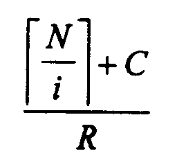
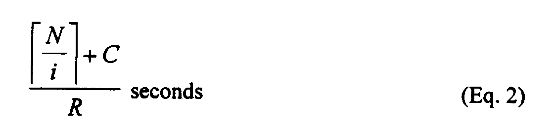
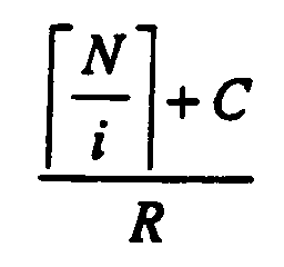
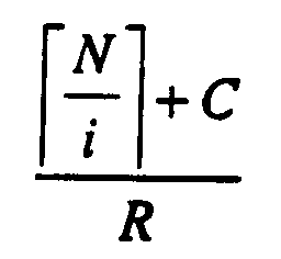
- An illustrative embodiment of the present invention is capable of transmitting an N byte packet over a common communications channel by: temporally dividing the common communications channel into time slots that have a duration equal to seconds, where i is a natural number greater than one, C is a constant and R is the transmission rate of the common communications channel in bytes per second; splitting the N byte packet into i p-packets; preparing an M byte training sequence; and transmitting the M byte training sequence and the p-packets over the common communications channel in consecutive time slots.
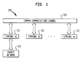
- FIG. 1 depicts a digital telecommunications system that transmits packetized data among a plurality of terminals.
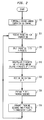
- FIG. 2 depicts a flowchart of the operation of the illustrative embodiment of the present invention.
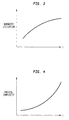
- FIG. 3 depicts a graph that indicates how the transmission rate utilization of a common communications channel varies as a function of i .
- FIG. 4 depicts a graph that indicates how the protocol complexity of the illustrative embodiment varies as a function of i .
- FIG. 5 depicts a block diagram of a hardware embodiment of the present invention.
- FIG 1 depicts an illustrative embodiment of the present invention in which digital telecommunications system 100 transmits packetized data among a plurality of terminals (e.g., terminal 111, terminal 112, etc.) who share a common communications channel 120 under the regulation of a multiple access layer protocol.
- Digital telecommunications system 100 could be, for example, a wireless system in which common communications channel 120 is some portion of the electromagnetic spectrum.
- the locations of some or all of the terminals can be mobile.
- some of the terminals can be wireless terminals and others can be base stations that enable the wireless terminals to communicate with other wireless terminals and with the wireline network.
- digital telecommunications system 100 could be a wireline system in which common communications channel 120 could be copper, optical fiber, coaxial cable or other wireline transmission medium or combination of the above.
- One or more of the terminals in the illustrative embodiment could also be connected to a packet network, such as an ATM network.
- a packet network such as an ATM network.
- One of the terminals could be, for example, a wireless base station, or head-end equipment in a fiber-coax system.
- Digital telecommunications system 100 requires that each terminal transmit an M byte training sequence prior to the transmission of a packet for the purposes of equalization and synchronization.
- the length of the training sequence varies from terminal to terminal and temporally and is based on, among other things, whether common communications channel 120 is wireless or wireline, whether the terminals are fixed or mobile, the modulation scheme used, the carrier frequency, the bit error rate of previous transmissions, and the weather and topology of the terrain near the terminals.
- the length of the training sequence transmitted by one terminal can be different than the length of the training sequence transmitted by another.
- the length of the training sequence can range from just a few bytes to hundreds of bytes. It will be clear to those skilled in the art how to make and use training sequences for packetized data, and to determine the length of the training sequences.
- each terminal generates variable-length messages for transmission to other terminals via common communications channel 120, under the regulation of a multiple access layer protocol.
- One possible protocol for regulating the use of common communications channel 120 could allow the transmission of a variable-length packet (following the transmission of a variable-length training sequence). Such a protocols tends to be complex and tends not to use the overall bandwidth capability of common communications channel 120 efficiently.
- An alternative protocol could require that each terminal partition each message into one or more fixed-length packets of N bytes and utilize fixed-length time slots in which to transmit the fixed-length packets and the training sequences.
- One or more fixed-length packets could be transmitted consecutively after a training sequence.
- a protocol that uses time slots and fixed-length packets tends to be less complex and tends to use the common channel bandwidth more efficiently than a multiple access layer protocol that permits variable-length packets. If fixed-length packets and slots are to be used, then the questions arises: What should be the duration of the time slot in relation to the size of the fixed-length packet?
- the duration of the time-slot could be equal to the amount of time required to transmit some fixed multiple number of packets plus the amount of time required to transmit a typical training sequence.
- This solution is advantageous because the cost of the training sequence is amortized over multiple packets.
- This solution is disadvantageous in terms of delay-throughput, however, because the terminal may have to delay the transmission of one packet until enough packets are available to fill the time slot. Analogously, if the terminal cannot delay the transmission of packets for long and must transmit each packet soon after it becomes available for transmission, and without waiting for other packets for fill-out the time slot, then this solution will waste the bandwidth of the common channel because the terminal will be using a time slot intended for multiple time packets to transmit fewer packets than it was designed to carry.
- a second solution is to set the duration of the time-slot to equal the amount of time required to transmit one fixed-length packet, regardless of the length of any given training sequence or of expected length of a typical training sequence.
- This solution is advantageous in terms of delay-throughput because the terminal does not need to wait for other packets in order to transmit a single packet.
- this solution is also advantageous in terms of efficiently using the bandwidth of the common channel because the terminal will never send a single packet in a time slot intended for multiple packets. This solution is, however, problematic given that the length of the training sequence varies over time.
- the training sequence may not always fill an integral number of time slots, and, therefore, a time slot may be only partially filled, which wastes the bandwidth of common communications channel 120. Furthermore, the probability that a given training sequence will not fill an integral number of time slots increases with the size of the time slot. In other words, for a given training sequence, larger time slots are less likely to be integrally filled than smaller time slots, and, therefore, are more wasteful of the bandwidth of common communications channel 120.
- the illustrative embodiment of the present invention partitions variable-length messages into one or more fixed-length packets and uses a time slot that is smaller than the amount of time required to transmit one fixed-length packet. More specifically, the length of the time slot is advantageously equal to an "approximate submultiple" of the amount of time required to transmit one fixed-length packet.
- This solution is advantageous in terms of delay-throughput because the terminal does not need to wait for other packets in order to transmit a single packet and is advantageous in terms of bandwidth utilization because the terminal will never send a single packet in a time slot for multiple packets, nor will it unduly waste bandwidth by transmitting a small training sequence in a long time slot.
- the term "approximate submultiple” means the function where N is the length of the packet, i is a natural number greater than one, C is a constant and the ceiling function means the smallest integer greater than or equal to x .
- the approximate submultiples of 53 are 27, 18, 14, 11, 9, 8, 7, 6, 5, 4, 3, 2 and 1.
- FIG. 2 depicts a flowchart of the operation of the illustrative embodiment as it transmits packetized data over common communications channel 120 (shown in FIG. 1).
- the method begins at step 210, which temporally divides common communications channel 120 into slots that have a duration equal to where N is length of the fixed-length packets, i is a natural number greater than one, C is a constant and R is the transmission rate of the common communications channel in bytes per second.
- the bandwidth utilization of the common channel tends to increase with larger values of i , but, as shown in FIG.
- i 3.
- the transmission rate R of common communications channel 120 is an empirical fact depending on the specific embodiment of the present invention and it will be clear to those skilled in the art how to determine the value for R .
- common communications channel 120 can be divided into temporal slots.
- one terminal or entity with access to common communications channel 120 transmits a pulse train on common communications channel 120 to the other terminals, which pulse pain is either implicitly or explicitly indicative of the slot boundaries and so that all of the terminals are synchronized with regard to the slot boundaries.
- the terminal receives one or more N byte fixed-length packets to be transmitted on common communications channel 120.
- each p-packet is encapsulated with Q bytes of encapsulation and/or is enlarged b y Z bytes.
- the process of encapsulation leaves the contents of the p-packet untouched and adds Q bytes as a header to the p-packet, whereas, in contrast, the process of enlargement alters the contents of the p-packet in such a manner as to require Z more bytes to hold the information of the p-packet.
- Encapsulation can be done to enhance error correction and detection, to enhance p-packet boundaries, to insert sequence numbers, to insert control information (such as the size of the payload), etc. It will be clear to those skilled in the art how to encapsulate p-packets for a specific embodiment of the present invention.
- Enlargement is typically performed for the purposes of error correction and detection and/or for cryptographic purposes. It will be clear to those skilled in the art how to enlarge p-packets for a specific embodiment of the present invention. P-packets can be encapsulated and the result enlarged and vice versa. Again, it will be clear to those skilled in the art how to perform both encapsulation and enlargement on a p-packet for a specific embodiment of the present invention. Alternatively, in some embodiments of the present invention, the p-packets are neither encapsulated nor enlarged. When the p-packets transmitted over common communications channel 120 are neither encapsulated nor enlarged, the value for C is advantageously zero (0).
- the value for C is advantageously Q + Z .
- the indication could be a number that explicitly indicates the length of the training sequence.
- the indication could be an implicit indicator that the last training sequence was too short and that the next should be longer, or that the last training sequence was too long and that the next should be shorter.
- the indication is advantageously transmitted by another terminal on common communications channel 120. It will be clear to those skilled in the art how to make and use a messaging system for indicating how long the training sequences should be.
- the illustrative embodiment prepares an M byte training sequence, in well known fashion.
- the illustrative embodiment transmits the M byte training sequence and the (possibly encapsulated) p-packets in consecutive slots, beginning at a slot boundary, under the regulation of the multiple access layer protocol. Any remaining portion of a time slot is padded, in well known fashion.
- the illustrative embodiment proceeds to step 220.
- FIG. 5 depicts a block diagram of a hardware embodiment of the present invention.
- Clock 530 is advantageously a highly precise clock whose frequency and phase are set by processor 540, in well known fashion, and whose output is used by both receiver 510 and transmitter 520 for determining when time slots begin and end. If terminal 111 sets the standard time slot frequency and phase for all of the terminals on common communications channel 120, then transmitter 520 is advantageously capable of transmitting the pulse train from clock to other terminals.
- Processor 540 is used for transmitting and receiving packetized data from packet network 121, for splitting packets into p-packets, for encapsulating and/or enlarging the p-packets, for unencapsulating and/or de-enlarging p-packets received over common communications channel 120 and for rejoining p-packets into fixed-length packets, all in well-known fashion.
- Receiver 510 receives p-packets, messages indicative of M , and when terminal 111 is not setting the standard time slot, the pulse train from another terminal over common communications channel 120
Landscapes
- Engineering & Computer Science (AREA)
- Computer Networks & Wireless Communication (AREA)
- Signal Processing (AREA)
- Data Exchanges In Wide-Area Networks (AREA)
- Time-Division Multiplex Systems (AREA)
- Small-Scale Networks (AREA)
- Use Of Switch Circuits For Exchanges And Methods Of Control Of Multiplex Exchanges (AREA)
- Mobile Radio Communication Systems (AREA)
Abstract
Description


Claims (10)
- A method of transmitting an N byte packet over a common communications channel, CHARACTERIZED BY:temporally dividing said common communications channel into time slots that have a duration equal toseconds, where i is a natural number greater than one, C is a constant and R is the transmission rate of said common communications channel in bytes per second;
 splitting said N byte packet into i p-packets;preparing an M byte training sequence; andtransmitting said M byte training sequence and said p-packets over said common communications channel in consecutive time slots.
 - The method of claim 1 further comprising the step of encapsulating each of said p-packets with Q bytes prior to said step of transmitting.
- The method of claim 2 wherein C is based on Q.
- The method of claim 1 further comprising the step of enlarging each of said p-packets by Z bytes prior to said step of transmitting.
- The method of claim 4 wherein C is based on Z.
- A terminal for transmitting an N byte packet over a common communications channel, said telecommunication system CHARACTERIZED BY:a clock for transmitting a pulse train that temporally divides said common communications channel into time slots that have a duration equal toseconds, where i is a natural number greater than one, C is a constant and R is the transmission rate of said common communications channel in bytes per second;
 a processor for splitting said N byte packet into i p-packets and for preparing an M byte training sequence; anda transmitter for receiving said pulse train and for transmitting said M byte training sequence and said p-packets over said common communications channel in consecutive time slots.
 - The terminal of claim 6 wherein said common communications channel is a wireline channel.
- The terminal of claim 6 further comprising a receiver for receiving a message indicative of M.
- The terminal of claim 6 further comprising an encapsulator for encapsulating each p-packet with Q bytes prior to transmission.
- The terminal of claim 9 wherein C is based on Q, N equals 53 and i equals 3.
Applications Claiming Priority (2)
| Application Number | Priority Date | Filing Date | Title |
|---|---|---|---|
| US781968 | 1985-09-30 | ||
| US08/781,968 US6014385A (en) | 1996-12-28 | 1996-12-28 | Method and apparatus for transmitting packetized data over a common communications channel |
Publications (2)
| Publication Number | Publication Date |
|---|---|
| EP0851636A1 true EP0851636A1 (en) | 1998-07-01 |
| EP0851636B1 EP0851636B1 (en) | 2011-09-07 |
Family
ID=25124514
Family Applications (1)
| Application Number | Title | Priority Date | Filing Date |
|---|---|---|---|
| EP97309726A Expired - Lifetime EP0851636B1 (en) | 1996-12-28 | 1997-12-02 | A method and terminal for transmitting packetized data over a common communications channel |
Country Status (3)
| Country | Link |
|---|---|
| US (1) | US6014385A (en) |
| EP (1) | EP0851636B1 (en) |
| JP (1) | JP3357282B2 (en) |
Cited By (2)
| Publication number | Priority date | Publication date | Assignee | Title |
|---|---|---|---|---|
| US7085248B1 (en) | 1999-07-05 | 2006-08-01 | Nokia Networks Oy | Method of identifying information addressed to a user in a communication system and a communication system |
| WO2016020155A1 (en) * | 2014-08-05 | 2016-02-11 | Robert Bosch Gmbh | Subscriber station for a bus system, and method for wideband can communication |
Families Citing this family (11)
| Publication number | Priority date | Publication date | Assignee | Title |
|---|---|---|---|---|
| US6195565B1 (en) * | 1998-03-03 | 2001-02-27 | Lucent Technologies Inc. | Bandwidth control in a packet-based data system |
| US6546009B1 (en) * | 1998-08-11 | 2003-04-08 | At&T Corp. | Method of reducing delays in packet data transmission |
| JP3075278B1 (en) * | 1999-02-19 | 2000-08-14 | ソニー株式会社 | Wireless communication method and wireless communication device |
| US6480506B1 (en) * | 1999-04-15 | 2002-11-12 | Sharewave Inc | Co-location negotiation scheme for wireless computer networks |
| DE19946594A1 (en) * | 1999-09-29 | 2001-04-12 | Zeiss Carl Jena Gmbh | Microscope, preferably for inspection in semiconductor manufacturing |
| KR100520306B1 (en) | 2003-06-30 | 2005-10-13 | 삼성전자주식회사 | An apparatus for controlling bandwidth, and method using the same |
| US8804751B1 (en) | 2005-10-04 | 2014-08-12 | Force10 Networks, Inc. | FIFO buffer with multiple stream packet segmentation |
| US8347339B2 (en) * | 2007-07-05 | 2013-01-01 | Coherent Logix, Incorporated | Transmission of multimedia streams to mobile devices with variable training information |
| US8199767B2 (en) * | 2008-05-09 | 2012-06-12 | Qualcomm Atheros, Inc. | Method and apparatus for adaptive time division multiplexing on a multi-channel wireline medium with colocated transceivers |
| US8335180B1 (en) | 2008-05-09 | 2012-12-18 | Qualcomm Incorporated | Method and apparatus for synchronizing and/or starting access points for adaptive time division multiplexing on a multi-channel wireline medium with colocated transceivers |
| US8315244B2 (en) | 2010-06-16 | 2012-11-20 | Harris Corporation | Wireless communication system with selective preamble synchronization portion and related methods |
Citations (4)
| Publication number | Priority date | Publication date | Assignee | Title |
|---|---|---|---|---|
| JPS63197148A (en) * | 1987-02-12 | 1988-08-16 | Mitsubishi Electric Corp | packet switching device |
| JPS63318843A (en) * | 1987-06-22 | 1988-12-27 | Hitachi Ltd | Packetization control circuit |
| US5065398A (en) * | 1988-05-16 | 1991-11-12 | Hitachi, Ltd. | TDMA satellite communication method and system |
| US5570362A (en) * | 1994-03-16 | 1996-10-29 | Fujitsu Limited | System for transferring variable length cells under ATM |
Family Cites Families (7)
| Publication number | Priority date | Publication date | Assignee | Title |
|---|---|---|---|---|
| DE3527329A1 (en) * | 1985-07-31 | 1987-02-05 | Philips Patentverwaltung | DIGITAL RADIO TRANSMISSION SYSTEM WITH VARIABLE TIME SLOT DURATION OF TIME SLOTS IN TIME MULTIPLEX FRAME |
| GB8623763D0 (en) * | 1986-10-03 | 1986-11-05 | Marconi Co Ltd | Communication system |
| DE68916231T2 (en) * | 1989-03-23 | 1995-02-02 | Ibm | Method and device for multiple access with distributed queues in a communication system. |
| US5369637A (en) * | 1991-04-03 | 1994-11-29 | U.S. Philips Corporation | Signal transmission system |
| DE69433872T2 (en) * | 1994-10-26 | 2005-07-14 | International Business Machines Corp. | Medium access control scheme for wireless local area networks with interleaved variable length time division frames |
| US5648958A (en) * | 1995-04-05 | 1997-07-15 | Gte Laboratories Incorporated | System and method for controlling access to a shared channel for cell transmission in shared media networks |
| US5590131A (en) * | 1995-05-30 | 1996-12-31 | Motorola, Inc. | Efficient distributed queueing random access method for the medium access control layer in networks with broadcast channels |
-
1996
- 1996-12-28 US US08/781,968 patent/US6014385A/en not_active Expired - Lifetime
-
1997
- 1997-12-02 EP EP97309726A patent/EP0851636B1/en not_active Expired - Lifetime
- 1997-12-16 JP JP34620797A patent/JP3357282B2/en not_active Expired - Fee Related
Patent Citations (4)
| Publication number | Priority date | Publication date | Assignee | Title |
|---|---|---|---|---|
| JPS63197148A (en) * | 1987-02-12 | 1988-08-16 | Mitsubishi Electric Corp | packet switching device |
| JPS63318843A (en) * | 1987-06-22 | 1988-12-27 | Hitachi Ltd | Packetization control circuit |
| US5065398A (en) * | 1988-05-16 | 1991-11-12 | Hitachi, Ltd. | TDMA satellite communication method and system |
| US5570362A (en) * | 1994-03-16 | 1996-10-29 | Fujitsu Limited | System for transferring variable length cells under ATM |
Non-Patent Citations (2)
| Title |
|---|
| PATENT ABSTRACTS OF JAPAN vol. 12, no. 476 (E - 693) 13 December 1988 (1988-12-13) * |
| PATENT ABSTRACTS OF JAPAN vol. 13, no. 166 (E - 746) 20 April 1989 (1989-04-20) * |
Cited By (4)
| Publication number | Priority date | Publication date | Assignee | Title |
|---|---|---|---|---|
| US7085248B1 (en) | 1999-07-05 | 2006-08-01 | Nokia Networks Oy | Method of identifying information addressed to a user in a communication system and a communication system |
| WO2016020155A1 (en) * | 2014-08-05 | 2016-02-11 | Robert Bosch Gmbh | Subscriber station for a bus system, and method for wideband can communication |
| CN106797334A (en) * | 2014-08-05 | 2017-05-31 | 罗伯特·博世有限公司 | Subscriber station for bus system and the method for broadband CAN communication |
| US10298415B2 (en) | 2014-08-05 | 2019-05-21 | Robert Bosch Gmbh | User station for a bus system and method for the wideband can communication |
Also Published As
| Publication number | Publication date |
|---|---|
| JP3357282B2 (en) | 2002-12-16 |
| EP0851636B1 (en) | 2011-09-07 |
| US6014385A (en) | 2000-01-11 |
| JPH10215265A (en) | 1998-08-11 |
Similar Documents
| Publication | Publication Date | Title |
|---|---|---|
| EP1135912B1 (en) | Packet transmission method and apparatus | |
| US6108314A (en) | Method, subscriber device, wireless router, and communication system efficiently utilizing the receive/transmit switching time | |
| US8300657B2 (en) | Modified range requests enabling bandwidth requests and state of health reporting | |
| US5568482A (en) | Low speed radio link system and method designed for ATM transport | |
| US5220563A (en) | Device for the transmission by an asynchronous network, notably an atm type network, of signalling data, channel by channel, assembled in a multiframe transmitted synchronously in out-of-band mode | |
| US6055242A (en) | Method and apparatus enabling synchronous transfer mode, variable length and packet mode access for multiple services over a broadband communication network | |
| EP1130841B1 (en) | Method and apparatus for TDM/TDMA communications | |
| US5930262A (en) | Method for TDMA management, central station, terminal station and network system to perform this method, frame structure used in this method | |
| US6014385A (en) | Method and apparatus for transmitting packetized data over a common communications channel | |
| US4586175A (en) | Method for operating a packet bus for transmission of asynchronous and pseudo-synchronous signals | |
| US7505475B2 (en) | Multiple access communication system and data transceiver | |
| EP0874530A1 (en) | Serial data transmission of variable length mini packets using statistical multiplexing | |
| EP0845917B1 (en) | Implementation of delay-critical services in a cable television system | |
| US10841674B2 (en) | Timeslot management method, a related network terminator, a related line terminator and an upstream signal frame structure for a time division multiple access system | |
| EP0868803A2 (en) | Transmission system with flexible frame structure | |
| US5809023A (en) | ATM method and apparatus utilizing decoupling minicells | |
| JPH10190740A (en) | Transmission/reception device for radio atm | |
| WO1997017778A1 (en) | Upstream access method in bidirectional telecommunication system | |
| CA2308405A1 (en) | A transmission system taking account of the requirements of the different kinds of traffic carried, and a corresponding transmitter and receiver | |
| GB2285201A (en) | Timing recovery apparatus | |
| KR100678188B1 (en) | Method and device for congestion control of reverse link in mobile communication system | |
| WO2001072082A1 (en) | Telecommunication process and system handling data organized in cells of variable length | |
| Ebert et al. | Efficient Encapsulation and Multiplexing in Meshed MF-TDMA Satellite Systems | |
| Angelopoulos et al. | MAC method offering high utilization of the return channel in HFC systems | |
| GB2344488A (en) | Permanent virtual circuit communication system |
Legal Events
| Date | Code | Title | Description |
|---|---|---|---|
| PUAI | Public reference made under article 153(3) epc to a published international application that has entered the european phase |
Free format text: ORIGINAL CODE: 0009012 |
|
| AK | Designated contracting states |
Kind code of ref document: A1 Designated state(s): DE GB |
|
| AX | Request for extension of the european patent |
Free format text: AL;LT;LV;MK;RO;SI |
|
| 17P | Request for examination filed |
Effective date: 19981204 |
|
| AKX | Designation fees paid |
Free format text: DE GB |
|
| RBV | Designated contracting states (corrected) |
Designated state(s): DE GB |
|
| 17Q | First examination report despatched |
Effective date: 20070925 |
|
| RAP3 | Party data changed (applicant data changed or rights of an application transferred) |
Owner name: LUCENT TECHNOLOGIES INC. |
|
| REG | Reference to a national code |
Ref country code: DE Ref legal event code: R079 Ref document number: 69740283 Country of ref document: DE Free format text: PREVIOUS MAIN CLASS: H04L0012560000 Ipc: H04L0012417000 |
|
| RIC1 | Information provided on ipc code assigned before grant |
Ipc: H04L 12/56 20060101ALI20110301BHEP Ipc: H04L 12/417 20060101AFI20110301BHEP |
|
| RTI1 | Title (correction) |
Free format text: A METHOD AND TERMINAL FOR TRANSMITTING PACKETIZED DATA OVER A COMMON COMMUNICATIONS CHANNEL |
|
| GRAP | Despatch of communication of intention to grant a patent |
Free format text: ORIGINAL CODE: EPIDOSNIGR1 |
|
| RAP1 | Party data changed (applicant data changed or rights of an application transferred) |
Owner name: ALCATEL-LUCENT USA INC. |
|
| GRAS | Grant fee paid |
Free format text: ORIGINAL CODE: EPIDOSNIGR3 |
|
| GRAA | (expected) grant |
Free format text: ORIGINAL CODE: 0009210 |
|
| AK | Designated contracting states |
Kind code of ref document: B1 Designated state(s): DE GB |
|
| REG | Reference to a national code |
Ref country code: GB Ref legal event code: FG4D |
|
| REG | Reference to a national code |
Ref country code: DE Ref legal event code: R096 Ref document number: 69740283 Country of ref document: DE Effective date: 20111103 |
|
| PLBE | No opposition filed within time limit |
Free format text: ORIGINAL CODE: 0009261 |
|
| STAA | Information on the status of an ep patent application or granted ep patent |
Free format text: STATUS: NO OPPOSITION FILED WITHIN TIME LIMIT |
|
| 26N | No opposition filed |
Effective date: 20120611 |
|
| REG | Reference to a national code |
Ref country code: DE Ref legal event code: R097 Ref document number: 69740283 Country of ref document: DE Effective date: 20120611 |
|
| REG | Reference to a national code |
Ref country code: GB Ref legal event code: 732E Free format text: REGISTERED BETWEEN 20131024 AND 20131030 |
|
| PGFP | Annual fee paid to national office [announced via postgrant information from national office to epo] |
Ref country code: GB Payment date: 20151221 Year of fee payment: 19 Ref country code: DE Payment date: 20151211 Year of fee payment: 19 |
|
| REG | Reference to a national code |
Ref country code: DE Ref legal event code: R119 Ref document number: 69740283 Country of ref document: DE |
|
| GBPC | Gb: european patent ceased through non-payment of renewal fee |
Effective date: 20161202 |
|
| PG25 | Lapsed in a contracting state [announced via postgrant information from national office to epo] |
Ref country code: DE Free format text: LAPSE BECAUSE OF NON-PAYMENT OF DUE FEES Effective date: 20170701 Ref country code: GB Free format text: LAPSE BECAUSE OF NON-PAYMENT OF DUE FEES Effective date: 20161202 |