EP0856343A1 - Dispositif et procédé pour la purification des composants organiques polymérisables - Google Patents
Dispositif et procédé pour la purification des composants organiques polymérisables Download PDFInfo
- Publication number
- EP0856343A1 EP0856343A1 EP98101475A EP98101475A EP0856343A1 EP 0856343 A1 EP0856343 A1 EP 0856343A1 EP 98101475 A EP98101475 A EP 98101475A EP 98101475 A EP98101475 A EP 98101475A EP 0856343 A1 EP0856343 A1 EP 0856343A1
- Authority
- EP
- European Patent Office
- Prior art keywords
- purifier
- liquid
- polymerizable organic
- organic compound
- set forth
- Prior art date
- Legal status (The legal status is an assumption and is not a legal conclusion. Google has not performed a legal analysis and makes no representation as to the accuracy of the status listed.)
- Granted
Links
- 150000002894 organic compounds Chemical class 0.000 title claims abstract description 68
- 238000000034 method Methods 0.000 title claims description 26
- 239000007788 liquid Substances 0.000 claims abstract description 142
- 238000004821 distillation Methods 0.000 claims abstract description 50
- SMZOUWXMTYCWNB-UHFFFAOYSA-N 2-(2-methoxy-5-methylphenyl)ethanamine Chemical compound COC1=CC=C(C)C=C1CCN SMZOUWXMTYCWNB-UHFFFAOYSA-N 0.000 claims abstract description 33
- NIXOWILDQLNWCW-UHFFFAOYSA-N 2-Propenoic acid Natural products OC(=O)C=C NIXOWILDQLNWCW-UHFFFAOYSA-N 0.000 claims abstract description 33
- 230000014759 maintenance of location Effects 0.000 claims abstract description 14
- 239000000470 constituent Substances 0.000 claims description 35
- 150000001735 carboxylic acids Chemical class 0.000 claims description 10
- 239000000463 material Substances 0.000 claims description 3
- 238000012856 packing Methods 0.000 claims description 2
- 150000002148 esters Chemical class 0.000 claims 4
- 238000006116 polymerization reaction Methods 0.000 abstract description 16
- 230000000717 retained effect Effects 0.000 abstract description 9
- NIXOWILDQLNWCW-UHFFFAOYSA-M Acrylate Chemical compound [O-]C(=O)C=C NIXOWILDQLNWCW-UHFFFAOYSA-M 0.000 description 12
- 238000000746 purification Methods 0.000 description 11
- 229920000642 polymer Polymers 0.000 description 10
- 239000002904 solvent Substances 0.000 description 9
- 238000010521 absorption reaction Methods 0.000 description 6
- -1 acrylic acid Chemical class 0.000 description 6
- 239000007864 aqueous solution Substances 0.000 description 6
- 238000004140 cleaning Methods 0.000 description 6
- 239000007789 gas Substances 0.000 description 6
- 238000000926 separation method Methods 0.000 description 6
- 230000001771 impaired effect Effects 0.000 description 5
- QIGBRXMKCJKVMJ-UHFFFAOYSA-N Hydroquinone Chemical compound OC1=CC=C(O)C=C1 QIGBRXMKCJKVMJ-UHFFFAOYSA-N 0.000 description 4
- CERQOIWHTDAKMF-UHFFFAOYSA-N Methacrylic acid Chemical compound CC(=C)C(O)=O CERQOIWHTDAKMF-UHFFFAOYSA-N 0.000 description 4
- XLYOFNOQVPJJNP-UHFFFAOYSA-N water Substances O XLYOFNOQVPJJNP-UHFFFAOYSA-N 0.000 description 4
- 238000001944 continuous distillation Methods 0.000 description 3
- 238000007254 oxidation reaction Methods 0.000 description 3
- 239000000243 solution Substances 0.000 description 3
- 238000003466 welding Methods 0.000 description 3
- KAKZBPTYRLMSJV-UHFFFAOYSA-N Butadiene Chemical compound C=CC=C KAKZBPTYRLMSJV-UHFFFAOYSA-N 0.000 description 2
- RRHGJUQNOFWUDK-UHFFFAOYSA-N Isoprene Chemical compound CC(=C)C=C RRHGJUQNOFWUDK-UHFFFAOYSA-N 0.000 description 2
- PPBRXRYQALVLMV-UHFFFAOYSA-N Styrene Chemical compound C=CC1=CC=CC=C1 PPBRXRYQALVLMV-UHFFFAOYSA-N 0.000 description 2
- 125000005907 alkyl ester group Chemical group 0.000 description 2
- QVGXLLKOCUKJST-UHFFFAOYSA-N atomic oxygen Chemical compound [O] QVGXLLKOCUKJST-UHFFFAOYSA-N 0.000 description 2
- 238000009835 boiling Methods 0.000 description 2
- 230000000052 comparative effect Effects 0.000 description 2
- 230000002542 deteriorative effect Effects 0.000 description 2
- 238000009792 diffusion process Methods 0.000 description 2
- 239000003112 inhibitor Substances 0.000 description 2
- 239000001301 oxygen Substances 0.000 description 2
- 229910052760 oxygen Inorganic materials 0.000 description 2
- 239000011295 pitch Substances 0.000 description 2
- QQONPFPTGQHPMA-UHFFFAOYSA-N propylene Natural products CC=C QQONPFPTGQHPMA-UHFFFAOYSA-N 0.000 description 2
- 125000004805 propylene group Chemical group [H]C([H])([H])C([H])([*:1])C([H])([H])[*:2] 0.000 description 2
- 229910001220 stainless steel Inorganic materials 0.000 description 2
- 239000010935 stainless steel Substances 0.000 description 2
- 239000012808 vapor phase Substances 0.000 description 2
- NLHHRLWOUZZQLW-UHFFFAOYSA-N Acrylonitrile Chemical compound C=CC#N NLHHRLWOUZZQLW-UHFFFAOYSA-N 0.000 description 1
- GAWIXWVDTYZWAW-UHFFFAOYSA-N C[CH]O Chemical group C[CH]O GAWIXWVDTYZWAW-UHFFFAOYSA-N 0.000 description 1
- VCUFZILGIRCDQQ-KRWDZBQOSA-N N-[[(5S)-2-oxo-3-(2-oxo-3H-1,3-benzoxazol-6-yl)-1,3-oxazolidin-5-yl]methyl]-2-[[3-(trifluoromethoxy)phenyl]methylamino]pyrimidine-5-carboxamide Chemical compound O=C1O[C@H](CN1C1=CC2=C(NC(O2)=O)C=C1)CNC(=O)C=1C=NC(=NC=1)NCC1=CC(=CC=C1)OC(F)(F)F VCUFZILGIRCDQQ-KRWDZBQOSA-N 0.000 description 1
- XTXRWKRVRITETP-UHFFFAOYSA-N Vinyl acetate Chemical compound CC(=O)OC=C XTXRWKRVRITETP-UHFFFAOYSA-N 0.000 description 1
- MZVQCMJNVPIDEA-UHFFFAOYSA-N [CH2]CN(CC)CC Chemical group [CH2]CN(CC)CC MZVQCMJNVPIDEA-UHFFFAOYSA-N 0.000 description 1
- 125000004183 alkoxy alkyl group Chemical group 0.000 description 1
- 238000010533 azeotropic distillation Methods 0.000 description 1
- 125000000484 butyl group Chemical group [H]C([*])([H])C([H])([H])C([H])([H])C([H])([H])[H] 0.000 description 1
- 239000003054 catalyst Substances 0.000 description 1
- 238000006243 chemical reaction Methods 0.000 description 1
- YACLQRRMGMJLJV-UHFFFAOYSA-N chloroprene Chemical compound ClC(=C)C=C YACLQRRMGMJLJV-UHFFFAOYSA-N 0.000 description 1
- 150000001875 compounds Chemical class 0.000 description 1
- 125000000113 cyclohexyl group Chemical group [H]C1([H])C([H])([H])C([H])([H])C([H])(*)C([H])([H])C1([H])[H] 0.000 description 1
- 238000010586 diagram Methods 0.000 description 1
- 125000004985 dialkyl amino alkyl group Chemical group 0.000 description 1
- 125000005448 ethoxyethyl group Chemical group [H]C([H])([H])C([H])([H])OC([H])([H])C([H])([H])* 0.000 description 1
- 125000001495 ethyl group Chemical group [H]C([H])([H])C([H])([H])* 0.000 description 1
- 230000001747 exhibiting effect Effects 0.000 description 1
- 239000008246 gaseous mixture Substances 0.000 description 1
- 125000003055 glycidyl group Chemical group C(C1CO1)* 0.000 description 1
- 239000012535 impurity Substances 0.000 description 1
- 125000002496 methyl group Chemical group [H]C([H])([H])* 0.000 description 1
- 239000000203 mixture Substances 0.000 description 1
- 238000012986 modification Methods 0.000 description 1
- 230000004048 modification Effects 0.000 description 1
- 230000003647 oxidation Effects 0.000 description 1
- 125000001436 propyl group Chemical group [H]C([*])([H])C([H])([H])C([H])([H])[H] 0.000 description 1
- 238000010992 reflux Methods 0.000 description 1
- 238000001577 simple distillation Methods 0.000 description 1
- 238000001256 steam distillation Methods 0.000 description 1
- 125000000391 vinyl group Chemical group [H]C([*])=C([H])[H] 0.000 description 1
Images


Classifications
-
- B—PERFORMING OPERATIONS; TRANSPORTING
- B01—PHYSICAL OR CHEMICAL PROCESSES OR APPARATUS IN GENERAL
- B01J—CHEMICAL OR PHYSICAL PROCESSES, e.g. CATALYSIS OR COLLOID CHEMISTRY; THEIR RELEVANT APPARATUS
- B01J19/00—Chemical, physical or physico-chemical processes in general; Their relevant apparatus
- B01J19/32—Packing elements in the form of grids or built-up elements for forming a unit or module inside the apparatus for mass or heat transfer
- B01J19/325—Attachment devices therefor, e.g. hooks, consoles, brackets
-
- B—PERFORMING OPERATIONS; TRANSPORTING
- B01—PHYSICAL OR CHEMICAL PROCESSES OR APPARATUS IN GENERAL
- B01D—SEPARATION
- B01D3/00—Distillation or related exchange processes in which liquids are contacted with gaseous media, e.g. stripping
- B01D3/14—Fractional distillation or use of a fractionation or rectification column
- B01D3/16—Fractionating columns in which vapour bubbles through liquid
- B01D3/22—Fractionating columns in which vapour bubbles through liquid with horizontal sieve plates or grids; Construction of sieve plates or grids
-
- B—PERFORMING OPERATIONS; TRANSPORTING
- B01—PHYSICAL OR CHEMICAL PROCESSES OR APPARATUS IN GENERAL
- B01D—SEPARATION
- B01D3/00—Distillation or related exchange processes in which liquids are contacted with gaseous media, e.g. stripping
- B01D3/14—Fractional distillation or use of a fractionation or rectification column
- B01D3/32—Other features of fractionating columns ; Constructional details of fractionating columns not provided for in groups B01D3/16 - B01D3/30
- B01D3/324—Tray constructions
- B01D3/326—Tray supports
-
- B—PERFORMING OPERATIONS; TRANSPORTING
- B01—PHYSICAL OR CHEMICAL PROCESSES OR APPARATUS IN GENERAL
- B01D—SEPARATION
- B01D53/00—Separation of gases or vapours; Recovering vapours of volatile solvents from gases; Chemical or biological purification of waste gases, e.g. engine exhaust gases, smoke, fumes, flue gases, aerosols
- B01D53/14—Separation of gases or vapours; Recovering vapours of volatile solvents from gases; Chemical or biological purification of waste gases, e.g. engine exhaust gases, smoke, fumes, flue gases, aerosols by absorption
- B01D53/18—Absorbing units; Liquid distributors therefor
-
- B—PERFORMING OPERATIONS; TRANSPORTING
- B01—PHYSICAL OR CHEMICAL PROCESSES OR APPARATUS IN GENERAL
- B01J—CHEMICAL OR PHYSICAL PROCESSES, e.g. CATALYSIS OR COLLOID CHEMISTRY; THEIR RELEVANT APPARATUS
- B01J19/00—Chemical, physical or physico-chemical processes in general; Their relevant apparatus
- B01J19/30—Loose or shaped packing elements, e.g. Raschig rings or Berl saddles, for pouring into the apparatus for mass or heat transfer
- B01J19/305—Supporting elements therefor, e.g. grids, perforated plates
-
- C—CHEMISTRY; METALLURGY
- C07—ORGANIC CHEMISTRY
- C07C—ACYCLIC OR CARBOCYCLIC COMPOUNDS
- C07C51/00—Preparation of carboxylic acids or their salts, halides or anhydrides
- C07C51/42—Separation; Purification; Stabilisation; Use of additives
- C07C51/43—Separation; Purification; Stabilisation; Use of additives by change of the physical state, e.g. crystallisation
- C07C51/44—Separation; Purification; Stabilisation; Use of additives by change of the physical state, e.g. crystallisation by distillation
-
- C—CHEMISTRY; METALLURGY
- C07—ORGANIC CHEMISTRY
- C07C—ACYCLIC OR CARBOCYCLIC COMPOUNDS
- C07C57/00—Unsaturated compounds having carboxyl groups bound to acyclic carbon atoms
- C07C57/02—Unsaturated compounds having carboxyl groups bound to acyclic carbon atoms with only carbon-to-carbon double bonds as unsaturation
- C07C57/03—Monocarboxylic acids
- C07C57/04—Acrylic acid; Methacrylic acid
-
- Y—GENERAL TAGGING OF NEW TECHNOLOGICAL DEVELOPMENTS; GENERAL TAGGING OF CROSS-SECTIONAL TECHNOLOGIES SPANNING OVER SEVERAL SECTIONS OF THE IPC; TECHNICAL SUBJECTS COVERED BY FORMER USPC CROSS-REFERENCE ART COLLECTIONS [XRACs] AND DIGESTS
- Y10—TECHNICAL SUBJECTS COVERED BY FORMER USPC
- Y10S—TECHNICAL SUBJECTS COVERED BY FORMER USPC CROSS-REFERENCE ART COLLECTIONS [XRACs] AND DIGESTS
- Y10S203/00—Distillation: processes, separatory
- Y10S203/22—Accessories
Definitions
- the present invention relates to a purifier and a purifying method for polymerizable organic compounds. Specifically, the present invention relates to a purifier and a purifying method with which polymerizable organic compounds (organic compounds which are easily polymerized) such as acrylic acid or methacrylic acid are efficiently purified by distillation or other processes, by effectively avoiding polymerization of the polymerizable organic compounds.
- polymerizable organic compounds organic compounds which are easily polymerized
- a polymerizable organic compound an organic compound which is easily polymerized
- a polymerization inhibitor such as acrylic acid or methacrylic acid
- the polymerizable organic compound When a polymerizable organic compound is distilled by the use of a conventional distiller, the polymerizable organic compound is substantially retained, in a liquid form, on a surface of a distiller constituent member (for example, a tray supporting member) of the distiller. Therefore, the retained liquid, that is, the polymerizable organic compound, is polymerized by, for example, heat application. As a result, a polymer is formed.
- a strainer is provided at a predetermined position so that the polymer is removed from the polymerized organic compound taken out of the distiller. Besides, the operation of the distiller is suspended at regular intervals for dismantling and checking of the distiller, so that the polymer adhering to inner surfaces of the distiller is washed away.
- the inventors eagerly studied a purifier and a purifying method with which a polymerizable organic compound could be efficiently purified. As a result, it was found that by controlling substantial retention of a liquid containing a polymerizable organic compound on a purifier constituent member inside the purifier, polymerization of the polymerizable organic compound was effectively prevented, thereby enabling effective purification of the same. In addition, it was also found that to control the substantial retention of the liquid, a liquid passing part for allowing the liquid to flow from the constituent member downward may be provided in the purifier constituent member inside the purifier. The present invention was completed based on this finding.
- the first object of the present invention is to provide a purifier with which polymerization of a polymerizable organic compound is effectively avoided when the polymerizable organic compound is purified by distillation or other processes so that efficient purification is performed.
- a purifier of the present invention for purifying a polymerizable organic compound is characterized in comprising a liquid passing part provided in a purifier constituent member inside the purifier, the liquid passing part allowing liquid containing the polymerizable organic compound to flow from the constituent member downward, so as to avoid substantial retention of the liquid on the constituent member.
- the liquid containing the polymerizable organic compound is allowed to smoothly flow from the constituent member downward through the liquid passing part, thereby causing no substantial retention of the liquid on the constituent member.
- polymerization which tends to occur when the liquid is retained on the surface of the constituent member thereby being heated is effectively prevented. Therefore, efficient purification of the liquid, that is, the polymerizable organic compound, is ensured.
- the second object of the present invention is to provide a purifying method with which polymerization of a polymerizable organic compound is effectively avoided when the polymerizable organic compound is purified by distillation or other processes so that efficient purification is performed.
- a purifying method of the present invention for purifying a polymerizable organic compound which uses a purifier incorporating a constituent member in which a liquid passing part is formed, is characterized in comprising the step of allowing liquid containing the polymerizable organic compound to flow from the constituent member downward through the liquid passing part, so as to avoid substantial retention of the liquid on the constituent member.
- the polymerization which tends to occur when the liquid is retained on the constituent member thereby being heated can be effectively avoided, and as a result the liquid, that is, the polymerizable organic compound, can be efficiently purified.
- Figure 1 is a block diagram illustrating a schematic arrangement of a producing device of a polymerizable organic compound which is equipped with a distillation column as a purifier of the present invention.
- Figure 2 is a side view illustrating an arrangement of principal parts of a tray supporting member as a distillation column constituent member inside the distillation column.
- Figure 3 is a cross-sectional view illustrating an arrangement of principal parts inside the distillation column.
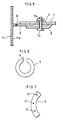
- Figure 4 is a plan view illustrating a principal part arrangement of the tray supporting member.
- Figure 5 is a cross-sectional view illustrating the principal part arrangement of the tray supporting member.
- Figure 6 is a plan view illustrating another principal part arrangement of the tray supporting member.
- Figure 7 is a plan view illustrating still another principal part arrangement of the tray supporting member.
- Polymerizable organic compounds in the present invention are organic compounds which are characterized in that they are easily polymerized by, for example, heat application.
- examples of such polymerizable organic compounds include: unsaturated carboxylic acids, such as acrylic acid, and methacrylic acid (hereinafter these two are generically called (meth)acrylic acid); alkyl esters of the unsaturated carboxylic acids, such as methyl (meth)acrylate, ethyl (meth)acrylate, propyl (meth)acrylate, butyl (meth)acrylate, 2-ethylhexyl (meth)acrylate, and cyclohexyl (meth)acrylate; hydroxylic alkyl esters of the unsaturated carboxylic acids, such as hydroxyethyl (meth)acrylate, and hydroxypropyl (meth)acrylate; dialkylaminoalkyl esters of the unsaturated carboxylic acids, such as dimethylaminoethyl (meth)acryl
- Purification in the present invention refers to (1) distillation, (2) diffusion, or (3) absorption of the polymerizable organic compound.
- distillation refers to separation of a liquid-form mixture into components by utilizing differences between vapor pressures of the components.
- Diffusion refers to expelling (removing) at least one component constituting a solution (dissolved in a solvent) out of the solution by bringing the solution into contact with a gas which does not contain the component.
- Absorption refers to causing at least one component of a gaseous mixture to be dissolved (absorbed) in a solvent.
- the acrylic acid is obtained by vapor phase oxidization of a material such as propylene in an oxygen-containing gas in the presence of an oxidation catalyst.
- a gas containing acrylic acid is produced in a reactor 11, and is introduced into the vicinity of a bottom of an absorption column 12.
- the gas thus produced through reaction is cooled with the use of water (solvent) introduced through a column top, and it is condensed to an acrylic acid aqueous solution.
- light boiling point components are removed from the acrylic acid aqueous solution.
- the acrylic acid aqueous solution from which light boiling point components have been removed is taken out from the bottom of the absorption column 12, and is introduced into the vicinity of a middle stage of a solvent separation column 13.
- the distillation column 14 is, for example, a multi-stage distillation column in which a plurality of trays are provided. The trays are fixed at predetermined positions inside the distillation column, supported by a tray supporting member.
- the tray supporting member as a constituent member inside the purifier is composed of a support ring 2, a lug 3, support beams 4, a washer 5, a clamp 6, a bolt 7a, and a nut 7b.
- the lug 3 is fixed on an inside wall 14a of the distillation column, by bolting or welding, for example.
- the support ring 2 in a ring form is fixed on the lug 3 by, for example, bolting or welding so that the tray 1 is held thereon.
- the support beams 4 in a bar form are fixed on the lug 3 by, for example, bolting or welding, so that they orthogonally cross each other.
- the support beams 4 have bolt holes (not shown), so that the tray 1 is fixed thereon by bolting.
- the support beams 4 are provided under the tray 1 so as to support it, thereby contributing to improvement of mechanical strength of the tray 1.
- the tray 1 is usually composed of a plurality of parts combined with each other, but for purposes of illustration, an integrally-formed one is shown in the drawings.
- the number of the support beams 4 may be appropriately determined, depending on a size and a weight of the tray 1, and it is not specifically limited. However, the number is preferably plural.
- the tray 1 is fixed on the support ring 2 by the washer 5, the clamp 6, the bolt 7a, and the nut 7b. More specifically, the tray 1 is fixed to the support ring 2 in the following manner: in a state where the support ring 2 is sandwiched between the tray 1 and the clamp 6, the bolt 7a pierces through a hole of the clamp 6, a hole of the tray 1, and the washer 5 from below in this order, then, the bolt 7a is fixed with the nut 7b.
- a liquid passing part which allows liquid such as the crude acrylic acid to smoothly flow down therethrough from surfaces of the tray 1 and the tray supporting member is provided in at least one part of the tray supporting member, that is, at least one selected from the group consisting of the support ring 2, the lug 3, the support beams 4, the washer 5, the clamp 6, the bolt 7a, and the nut 7b, so that the liquid would not be substantially retained on the surfaces of the tray 1 and the tray supporting member.
- the liquid passing part is formed in a horizontal portion (a portion which is substantially horizontal when being set inside the distillation column 14) of at least one among the support ring 2, the lug 3, the support beams 4, the washer 5, the clamp 6, the bolt 7a, and the nut 7b, so that the liquid passing part vertically pierces the horizontal portion.
- a liquid hole 8 as the liquid passing part may be provided in a portion of the support ring 2 in the vicinity of the inside wall 14a of the distillation column, as illustrated in Figure 5.
- the liquid hole 8 may be formed at least at a position such that the tray 1 does not cover the whole part of the liquid hole 8.
- a hole with a size substantially equal to the size of the liquid hole 8 may be formed in the tray 1 at a position corresponding to the liquid hole 8.
- the size and the number of the liquid hole 8 to be provided in the support ring 2 are not particularly limited, and may be appropriately determined depending on the size of the support ring 2 or the like. To be more specific, the size and the number of the liquid hole 8 may be set in ranges such that the liquid smoothly flows from on the tray supporting member downward while a mechanical strength required of the support ring 2 for holding the tray 1 is not impaired. It should be noted that it is not preferable to form the liquid hole 8 extremely large, since in such a case the liquid flows down without sufficient gas-liquid contact on the tray 1, thereby deteriorating distillation performance of the distillation column 14. Besides, it is not preferable as well to form the liquid hole 8 extremely small, since in such a case the liquid is not allowed to smoothly flow down, thereby making it impossible to effectively prevent polymerization.
- a shape of the liquid hole 8 (a shape of an aperture) is not particularly limited, and the liquid hole 8 may have various shapes such as a circular shape, a semi-circular shape, an oval shape, or a polygonal shape. But the circular shape or the semi-circular shape is preferable.
- intervals (pitches) of the liquid holes 8 are not specifically limited, and they may be appropriately determined depending on the size of the support ring 2, the size and the number of the liquid holes 8, and the like. More specifically, for example, the liquid holes 8 may be arranged at intervals such that the liquid smoothly flows from on the tray supporting member downward while a mechanical strength required of the support ring 2 for holding the tray 1 is not impaired.
- the liquid holes 8 with a diameter of 3 mm to 30 mm, or preferably 5 mm to 20 mm, or more preferably 6 mm to 15 mm may be arranged at intervals of 25 mm to 500 mm, or preferably 50 mm to 400 mm, or more preferably 100 mm to 200 mm.
- a cutout 9 as the liquid passing part may be formed in the washer 5, as illustrated in Figure 6.
- a size of the cutout 9 as the liquid passing part to be formed in the washer 5 is not particularly limited, and it may be set so that the liquid smoothly flows from on the tray supporting member downward while a function of the washer 5 is not impaired. By doing so, the liquid can be allowed to smoothly flow down from on surfaces of the tray 1 and the tray supporting member.
- a liquid hole (not shown) as the liquid passing parts may be formed in the support beams 4.
- the liquid hole of the support beams 4 may be formed at least at a position such that the tray 1 does not cover the whole part of the liquid hole. Note that in the case where the liquid hole is formed at a position such that the whole part of the liquid hole is covered by the tray 1, a hole with a size substantially equal to the size of the liquid hole may be formed in the tray 1 at a position corresponding to the liquid hole. By doing so, the liquid can be allowed to smoothly flow down from on surfaces of the tray 1 and the tray supporting member.
- the size and the number of the liquid hole to be provided in the support beams 4 are not particularly limited, and may be appropriately determined depending on the size of the support beams 4 or the like. To be more specific, the size and the number of the liquid hole may be set in ranges such that the liquid smoothly flows from on the tray supporting member downward while a mechanical strength required of the support beams 4 for holding the tray 1 is not impaired.
- a shape of the liquid hole (a shape of an aperture) is not particularly limited, and the liquid hole may have various shapes such as a circular shape, a semi-circular shape, an oval shape, or a polygonal shape. But, the circular shape or the semi-circular shape is preferable.
- intervals (pitches) of the liquid holes are not specifically limited, and they may be appropriately determined depending on the size of the support beams 4, the size and the number of the liquid holes, and the like. More specifically, for example, the liquid holes may be arranged at intervals such that the liquid smoothly flows from on the tray supporting member downward while a mechanical strength required of the support beams 4 for supporting the tray 1 is not impaired.
- the liquid holes with a diameter of 3 mm to 30 mm, or preferably 5 mm to 20 mm, or more preferably 6 mm to 15 mm may be arranged, desirably along a center line of the support beam 4 running in the lengthwise direction thereof, at 50 mm to 500 mm intervals, or preferably 100 mm to 400 mm intervals, or more preferably 100 mm to 200 mm intervals.
- a liquid hole (not shown) as the liquid passing part may be formed in the lug 3.
- the liquid hole in the lug 3 may have a size substantially equal to the liquid hole (8) formed in the support ring 2 and/or the support beams 4, and may be provided at a position corresponding to the liquid hole (8). By doing so, the liquid can be allowed to smoothly flow down from on surfaces of the tray 1 and the tray supporting member.
- the liquid passing part may be formed in at least one part of the tray supporting member, that is, in at least one selected from the group consisting of the support ring 2, the lug 3, the support beams 4, the washer 5, the clamp 6, the bolt 7a, and the nut 7b, so that the liquid smoothly flows down from on the surfaces of the tray 1 and the tray supporting member.
- the polymerizable organic compounds can be produced.
- the polymerizable organic compounds can be efficiently purified, with polymerization of the polymerizable organic compounds effectively prevented.
- the operative conditions for the producing device, particularly the operative conditions for the distillation column 14, are not particularly limited, and may be appropriately determined, depending on properties of the polymerizable organic compounds, types of impurities contained in the liquid, and the like.
- the liquid passing part which allows the liquid to flow down from on the tray supporting member is formed in the tray supporting member as the constituent member of the distillation column 14, so as to avoid substantial retention of the liquid containing the polymerizable organic compounds on the tray supporting member.
- the distillation column 14 is arranged so that in a horizontal portion of the tray supporting member, the liquid passing part (liquid hole and/or cutout) is formed so as to pierce the horizontal portion in a vertical direction.
- the tray supporting member is composed of at least the support ring, the lug, the support beams, the washer, and the clamp. Further, the liquid passing part is formed in at least one member selected from the group consisting of the support ring, the lug, the support beams, the washer, and the clamp.
- liquid such as crude acrylic acid or the like is allowed to smoothly flow down from on the surfaces of tray 1 and the tray supporting member through the liquid passing part. Therefore, the liquid is by no means substantially retained on the surfaces of the tray 1 and the tray supporting member. As a result, the polymerization, which tends to occur when on the surfaces of the tray 1 and the tray supporting member the liquid is retained and heated, can be effectively avoided, thereby ensuring efficient purification of the liquid, that is, the polymerizable organic compound.
- the purifier of the present invention for purifying a polymerizable organic compound is characterized in comprising an arrangement for purifying a polymerizable organic compound without causing substantial retention of the liquid on said constituent member.
- the purifying method of the present invention for purifying a polymerizable organic compound which utilizes a purifier incorporating a constituent member in which a liquid passing part is formed, comprises the step of allowing liquid containing the polymerizable organic compound to flow down from on the constituent member through the liquid passing part, so as to avoid substantial retention of the liquid on the constituent member.
- the polymerization which tends to occur when the liquid is retained on the constituent member and is heated can be effectively prevented. Therefore, the liquid, that is, the polymerizable organic compound, can be efficiently purified.
- the purifier and the purifying method of the present invention are not limited to the above example case.
- a case where the distillation column 14 which is a multi-stage distillation column is used as the purifier and the liquid passing part is formed in the tray supporting member is taken as example, but in the case where a packed column, for example, is used as the purifier, the liquid passing part may be formed in a packing material holding member as a constituent member inside the purifier.
- a reactive gas containing acrylic acid which had been obtained as a result of contact vapor-phase oxidization of propylene, was brought into contact with water, and an acrylic acid aqueous solution was obtained. Then, crude acrylic acid was obtained by separating water from the acrylic acid aqueous solution. The crude acrylic acid was distilled for purification, and as a result acrylic acid as a polymerizable organic compound was obtained.
- a multi-stage distillation column made of stainless steel (SUS316) and having an inner diameter of 1800 mm, was used as a distillation column (purifier). Inside the distillation column, 50 sieve trays made of stainless steel (SUS316) were installed. Therefore, the distillation column had 50 stages.
- the sieve trays were arranged as described above, that is, so that they were fixed inside the distillation column by the use of the tray supporting members.
- a support ring as one part of each tray supporting member had a width of 50 mm, and 28 liquid holes in a circular shape with a diameter of 6 mm each were formed at 200 mm intervals in each support ring.
- liquid holes with a size substantially equal to the size of the liquid holes in the support ring were formed at positions corresponding to the above liquid holes in the support ring.
- a strainer for removing polymers from the acrylic acid to be taken out from the distillation column was installed at a predetermined position in the distillation column.
- the distillation column thus arranged was continuously operated at a temperature of 63°C and a pressure of 35 mmHg at the column top, at a temperature of 100°C and a pressure of 120 mmHg at the column bottom, and at a reflux ratio of 1.4.
- Hydroquinone was used as a polymerization inhibitor.
- the hydroquinone was added to a refluxed liquid so that a ratio thereof to steam in the distillation column was 50 ppm. Further, oxygen-containing gas was continuously supplied at a predetermined rate, into the distillation column through the column bottom.
- distillation of the crude acrylic acid was continued about one month. Thereafter, the distillation column was dismantled and checked, to measure an amount of polymer adhering to the sieve trays. The frequency (cleaning frequency) of cleaning of the strainer so as to remove the polymer therefrom while the continuous distillation was carried out was also checked. The results are shown in Table 1 below.
- the continuous distillation with respect to the crude acrylic acid was carried out about one month in the same operative conditions as those in Example 1, except that the number of the liquid holes was increased as compared with Example 1 and the 200 mm intervals were changed to 100 mm intervals. Then, an amount of produced polymer was measured, while the strainer cleaning frequency was checked. The result is shown in Table 1 below.
Landscapes
- Chemical & Material Sciences (AREA)
- Organic Chemistry (AREA)
- Chemical Kinetics & Catalysis (AREA)
- Physics & Mathematics (AREA)
- Thermal Sciences (AREA)
- Engineering & Computer Science (AREA)
- Oil, Petroleum & Natural Gas (AREA)
- Crystallography & Structural Chemistry (AREA)
- Analytical Chemistry (AREA)
- General Chemical & Material Sciences (AREA)
- Vaporization, Distillation, Condensation, Sublimation, And Cold Traps (AREA)
- Organic Low-Molecular-Weight Compounds And Preparation Thereof (AREA)
Applications Claiming Priority (3)
| Application Number | Priority Date | Filing Date | Title |
|---|---|---|---|
| JP9018261A JPH10212249A (ja) | 1997-01-31 | 1997-01-31 | 易重合性有機化合物の精製方法および精製装置 |
| JP18261/97 | 1997-01-31 | ||
| JP1826197 | 1997-01-31 |
Publications (2)
| Publication Number | Publication Date |
|---|---|
| EP0856343A1 true EP0856343A1 (fr) | 1998-08-05 |
| EP0856343B1 EP0856343B1 (fr) | 2004-01-02 |
Family
ID=11966745
Family Applications (1)
| Application Number | Title | Priority Date | Filing Date |
|---|---|---|---|
| EP98101475A Expired - Lifetime EP0856343B1 (fr) | 1997-01-31 | 1998-01-28 | Dispositif et procédé pour la purification des composants organiques polymérisables |
Country Status (9)
| Country | Link |
|---|---|
| US (1) | US6214174B1 (fr) |
| EP (1) | EP0856343B1 (fr) |
| JP (1) | JPH10212249A (fr) |
| KR (1) | KR100330194B1 (fr) |
| CN (1) | CN1182098C (fr) |
| DE (1) | DE69820804T2 (fr) |
| ID (1) | ID19843A (fr) |
| MY (1) | MY120443A (fr) |
| TW (1) | TW350783B (fr) |
Cited By (8)
| Publication number | Priority date | Publication date | Assignee | Title |
|---|---|---|---|---|
| EP1066872A1 (fr) * | 1999-07-06 | 2001-01-10 | Nippon Shokubai Co., Ltd. | Procédè et dispositif pour l'absorption de composés acryliques |
| US6500982B1 (en) | 1999-06-28 | 2002-12-31 | Rohm And Haas Company | Process for preparing (meth) acrylic acid |
| EP1279429A1 (fr) * | 2001-07-23 | 2003-01-29 | Nippon Shokubai Co., Ltd. | Colonne à fond perforé sans conduite de descente |
| WO2003047713A3 (fr) * | 2001-12-06 | 2003-09-18 | Basf Ag | Bride pour relier de maniere amovible un plateau de colonne et une bague d'appui dans une colonne |
| US6755943B1 (en) | 1999-02-18 | 2004-06-29 | Nippon Shokubai Co., Ltd. | Perforated tray without downcomer, perforated tray tower without downcomer |
| WO2006069693A1 (fr) * | 2004-12-22 | 2006-07-06 | Basf Aktiengesellschaft | Colonne a plateaux, et procede de transfert de matiere dans une colonne a plateaux |
| US7282118B2 (en) | 2000-04-14 | 2007-10-16 | Nippon Shokubai Co., Ltd. | Method for production of easily polymerizable substance and purification apparatus |
| WO2009039922A1 (fr) * | 2007-09-25 | 2009-04-02 | Outotec, Oyj | Bague de support destinée à recevoir un élément de type plaque dans un récipient |
Families Citing this family (14)
| Publication number | Priority date | Publication date | Assignee | Title |
|---|---|---|---|---|
| JP3787261B2 (ja) * | 1999-04-16 | 2006-06-21 | 株式会社日本触媒 | 易重合性化合物の重合防止方法 |
| CN1167486C (zh) * | 1999-06-03 | 2004-09-22 | 株式会社日本触媒 | 用于含有易堵塞性物质的有机化合物的精制塔及精制法 |
| JP2001081050A (ja) * | 1999-09-10 | 2001-03-27 | Nippon Shokubai Co Ltd | 易重合性化合物の取り扱い装置および取り扱い方法 |
| JP4527825B2 (ja) * | 1999-12-28 | 2010-08-18 | 株式会社日本触媒 | 易重合性化合物の熱交換方法 |
| KR20020009969A (ko) * | 2000-07-28 | 2002-02-02 | 토마스 케이. 맥브라이드 | 적층된 분류 트레이를 구비하는 분류 칼럼 |
| JP4233007B2 (ja) * | 2001-09-28 | 2009-03-04 | 株式会社日本触媒 | 低熱伝導性材料が付設されている精製装置 |
| US20040104108A1 (en) * | 2002-12-03 | 2004-06-03 | Mason Robert Michael | High capacity purification of thermally unstable compounds |
| CN1330410C (zh) * | 2003-01-15 | 2007-08-08 | 三菱丽阳株式会社 | 易聚合性物质处理装置用支撑梁和易聚合性物质处理装置 |
| JP2005336122A (ja) * | 2004-05-28 | 2005-12-08 | Mitsubishi Chemicals Corp | (メタ)アクリル酸又は(メタ)アクリル酸エステルの製造方法 |
| CN104474732A (zh) * | 2014-10-23 | 2015-04-01 | 中国石油化工股份有限公司 | 一种塔盘连接装置 |
| BR112017013741A2 (pt) * | 2014-12-23 | 2018-03-13 | Sulzer Chemtech Ag | aparelhos de bandeja de contato vapor-líquido |
| US10684071B2 (en) | 2017-08-25 | 2020-06-16 | Praxair Technology, Inc. | Annular divided wall column for an air separation unit |
| US10578357B2 (en) * | 2017-08-25 | 2020-03-03 | Praxair Technology, Inc. | Annular divided wall column with ring shaped collectors and distributers for an air separation unit |
| WO2020024137A1 (fr) * | 2018-08-01 | 2020-02-06 | 乔治洛德方法研究和开发液化空气有限公司 | Procédé d'installation de plateaux dans une tour à plaques |
Citations (6)
| Publication number | Priority date | Publication date | Assignee | Title |
|---|---|---|---|---|
| US3717553A (en) * | 1969-06-06 | 1973-02-20 | Rohm & Haas | Process and apparatus for the distillation of a vinyl monomer |
| US3988213A (en) * | 1972-09-25 | 1976-10-26 | Nippon Shokubai Kagaku Kogyo Co., Ltd. | Method of distilling vinyl compounds |
| US4174363A (en) * | 1978-03-10 | 1979-11-13 | Union Carbide Corporation | Vapor-liquid contacting tray with vapor thrust means |
| US4184857A (en) * | 1976-04-05 | 1980-01-22 | Jgc Corporation | Stripping column and process for removal of volatile matter |
| US4374000A (en) * | 1981-02-02 | 1983-02-15 | Cosden Technology, Inc. | Method for controlling the formation of polymer accumulations during distillation of a vinylaromatic monomer |
| US4442048A (en) * | 1981-02-02 | 1984-04-10 | Cosden Technology, Inc. | Method and apparatus for controlling the formation of polymer accumulations during distillation of a vinylaromatic monomer |
Family Cites Families (8)
| Publication number | Priority date | Publication date | Assignee | Title |
|---|---|---|---|---|
| US4051206A (en) * | 1976-05-10 | 1977-09-27 | Uop Inc. | Sieve-type fractionation trays |
| US4028443A (en) * | 1976-09-24 | 1977-06-07 | E. I. Du Pont De Nemours And Company | Distillation apparatus |
| US4247521A (en) * | 1979-08-15 | 1981-01-27 | Union Carbide Corporation | Liquid-liquid contacting system |
| US4405449A (en) * | 1980-08-29 | 1983-09-20 | Procon International Inc. | Process for vapor-liquid contacting and fractional distillation |
| US4744929A (en) * | 1986-07-17 | 1988-05-17 | Norton Company | Support device for a packed column |
| JPH085842B2 (ja) | 1986-08-07 | 1996-01-24 | 三井東圧化学株式会社 | 2−ヒドロキシアルキル(メタ)アクリレ−トの製造法 |
| US4814117A (en) * | 1987-12-21 | 1989-03-21 | Max Leva | Packing support for gas - liquid contact towers |
| US5069830A (en) * | 1990-02-20 | 1991-12-03 | Norton Company | Non-welded support plate or bed limiter for packed towers and method of making same |
-
1997
- 1997-01-31 JP JP9018261A patent/JPH10212249A/ja not_active Withdrawn
-
1998
- 1998-01-26 CN CNB981001742A patent/CN1182098C/zh not_active Expired - Fee Related
- 1998-01-26 ID IDP980095A patent/ID19843A/id unknown
- 1998-01-26 KR KR1019980002397A patent/KR100330194B1/ko not_active Expired - Fee Related
- 1998-01-26 TW TW087101104A patent/TW350783B/zh not_active IP Right Cessation
- 1998-01-26 MY MYPI98000369A patent/MY120443A/en unknown
- 1998-01-28 EP EP98101475A patent/EP0856343B1/fr not_active Expired - Lifetime
- 1998-01-28 US US09/015,053 patent/US6214174B1/en not_active Expired - Lifetime
- 1998-01-28 DE DE69820804T patent/DE69820804T2/de not_active Expired - Lifetime
Patent Citations (6)
| Publication number | Priority date | Publication date | Assignee | Title |
|---|---|---|---|---|
| US3717553A (en) * | 1969-06-06 | 1973-02-20 | Rohm & Haas | Process and apparatus for the distillation of a vinyl monomer |
| US3988213A (en) * | 1972-09-25 | 1976-10-26 | Nippon Shokubai Kagaku Kogyo Co., Ltd. | Method of distilling vinyl compounds |
| US4184857A (en) * | 1976-04-05 | 1980-01-22 | Jgc Corporation | Stripping column and process for removal of volatile matter |
| US4174363A (en) * | 1978-03-10 | 1979-11-13 | Union Carbide Corporation | Vapor-liquid contacting tray with vapor thrust means |
| US4374000A (en) * | 1981-02-02 | 1983-02-15 | Cosden Technology, Inc. | Method for controlling the formation of polymer accumulations during distillation of a vinylaromatic monomer |
| US4442048A (en) * | 1981-02-02 | 1984-04-10 | Cosden Technology, Inc. | Method and apparatus for controlling the formation of polymer accumulations during distillation of a vinylaromatic monomer |
Cited By (14)
| Publication number | Priority date | Publication date | Assignee | Title |
|---|---|---|---|---|
| US6755943B1 (en) | 1999-02-18 | 2004-06-29 | Nippon Shokubai Co., Ltd. | Perforated tray without downcomer, perforated tray tower without downcomer |
| US6500982B1 (en) | 1999-06-28 | 2002-12-31 | Rohm And Haas Company | Process for preparing (meth) acrylic acid |
| EP1066872A1 (fr) * | 1999-07-06 | 2001-01-10 | Nippon Shokubai Co., Ltd. | Procédè et dispositif pour l'absorption de composés acryliques |
| US6667419B1 (en) | 1999-07-06 | 2003-12-23 | Nippon Shokubai Co., Ltd. | Method for absorption of acrylic compound and apparatus therefor |
| US7282118B2 (en) | 2000-04-14 | 2007-10-16 | Nippon Shokubai Co., Ltd. | Method for production of easily polymerizable substance and purification apparatus |
| US7235158B2 (en) | 2001-07-23 | 2007-06-26 | Nippon Shokubai Co., Ltd. | Perforated tray column without downcomer |
| EP1279429A1 (fr) * | 2001-07-23 | 2003-01-29 | Nippon Shokubai Co., Ltd. | Colonne à fond perforé sans conduite de descente |
| WO2003047713A3 (fr) * | 2001-12-06 | 2003-09-18 | Basf Ag | Bride pour relier de maniere amovible un plateau de colonne et une bague d'appui dans une colonne |
| US7155801B2 (en) | 2001-12-06 | 2007-01-02 | Basf Aktiengesellschaft | Method for releasably connecting a column plate to a supporting ring in a column via a clamp |
| DE10295577B4 (de) * | 2001-12-06 | 2009-01-02 | Basf Se | Verwendung einer Klammer zur lösbaren Verbindung eines Kolonnenbodens mit einem Auflagering in einer Kolonne |
| WO2006069693A1 (fr) * | 2004-12-22 | 2006-07-06 | Basf Aktiengesellschaft | Colonne a plateaux, et procede de transfert de matiere dans une colonne a plateaux |
| WO2009039922A1 (fr) * | 2007-09-25 | 2009-04-02 | Outotec, Oyj | Bague de support destinée à recevoir un élément de type plaque dans un récipient |
| EA017650B1 (ru) * | 2007-09-25 | 2013-02-28 | Оутотек Ойй | Устройство для разделения ступеней конвертера |
| US8603409B2 (en) | 2007-09-25 | 2013-12-10 | Outotec Oyj | Support ring for accommodating a plate-like element in a vessel |
Also Published As
| Publication number | Publication date |
|---|---|
| DE69820804D1 (de) | 2004-02-05 |
| EP0856343B1 (fr) | 2004-01-02 |
| MY120443A (en) | 2005-10-31 |
| CN1182098C (zh) | 2004-12-29 |
| JPH10212249A (ja) | 1998-08-11 |
| KR100330194B1 (ko) | 2002-08-24 |
| DE69820804T2 (de) | 2004-11-25 |
| TW350783B (en) | 1999-01-21 |
| US6214174B1 (en) | 2001-04-10 |
| KR19980070872A (ko) | 1998-10-26 |
| CN1189485A (zh) | 1998-08-05 |
| ID19843A (id) | 1998-08-06 |
Similar Documents
| Publication | Publication Date | Title |
|---|---|---|
| EP0856343B1 (fr) | Dispositif et procédé pour la purification des composants organiques polymérisables | |
| CN100589861C (zh) | 容易聚合化合物用蒸馏装置 | |
| US7326323B2 (en) | High capacity purification of thermally unstable compounds | |
| JP2003033601A (ja) | 無堰多孔板塔 | |
| EP2311791A1 (fr) | Procédé de production d'un composé d'acide (meth)acrylique | |
| US7155801B2 (en) | Method for releasably connecting a column plate to a supporting ring in a column via a clamp | |
| US6448438B1 (en) | Method for purifying acrylic acid | |
| KR102519257B1 (ko) | 순수 2-에틸헥실 아크릴레이트 또는 순수 2-프로필헵틸 아크릴레이트를 상응하는 조질 알킬 아크릴레이트로부터 증류에 의해 단리하는 방법 | |
| JP2005239564A (ja) | (メタ)アクリル酸エステルの製造方法 | |
| KR102521727B1 (ko) | 조질 n-부틸 또는 이소부틸 아크릴레이트로부터 증류에 의해 순수 n-부틸 또는 이소부틸 아크릴레이트를 단리하는 방법 | |
| RU2352379C2 (ru) | Емкость для легко полимеризуемого соединения | |
| CA2655816C (fr) | Procede de purification de composes polymerisables | |
| US7892403B2 (en) | Handling device and producing system of easy-to-polymerize compound | |
| CN100427451C (zh) | (甲基)丙烯酸或(甲基)丙烯酸酯的制备方法 | |
| KR102519200B1 (ko) | 조질 t-부틸 (메트)아크릴레이트로부터 증류에 의해 순수 t-부틸 (메트)아크릴레이트를 단리하는 방법 | |
| US7625467B2 (en) | Support beam for easily polymerizeable substance treatment device and easily polymerizeable substance treatment device |
Legal Events
| Date | Code | Title | Description |
|---|---|---|---|
| PUAI | Public reference made under article 153(3) epc to a published international application that has entered the european phase |
Free format text: ORIGINAL CODE: 0009012 |
|
| AK | Designated contracting states |
Kind code of ref document: A1 Designated state(s): BE DE FR |
|
| AX | Request for extension of the european patent |
Free format text: AL;LT;LV;MK;RO;SI |
|
| 17P | Request for examination filed |
Effective date: 19981230 |
|
| AKX | Designation fees paid |
Free format text: BE DE FR |
|
| RBV | Designated contracting states (corrected) |
Designated state(s): BE DE FR |
|
| 17Q | First examination report despatched |
Effective date: 20010607 |
|
| GRAP | Despatch of communication of intention to grant a patent |
Free format text: ORIGINAL CODE: EPIDOSNIGR1 |
|
| GRAS | Grant fee paid |
Free format text: ORIGINAL CODE: EPIDOSNIGR3 |
|
| GRAA | (expected) grant |
Free format text: ORIGINAL CODE: 0009210 |
|
| AK | Designated contracting states |
Kind code of ref document: B1 Designated state(s): BE DE FR |
|
| REF | Corresponds to: |
Ref document number: 69820804 Country of ref document: DE Date of ref document: 20040205 Kind code of ref document: P |
|
| ET | Fr: translation filed | ||
| PLBE | No opposition filed within time limit |
Free format text: ORIGINAL CODE: 0009261 |
|
| STAA | Information on the status of an ep patent application or granted ep patent |
Free format text: STATUS: NO OPPOSITION FILED WITHIN TIME LIMIT |
|
| 26N | No opposition filed |
Effective date: 20041005 |
|
| PGFP | Annual fee paid to national office [announced via postgrant information from national office to epo] |
Ref country code: BE Payment date: 20140114 Year of fee payment: 17 Ref country code: DE Payment date: 20140122 Year of fee payment: 17 |
|
| PGFP | Annual fee paid to national office [announced via postgrant information from national office to epo] |
Ref country code: FR Payment date: 20140108 Year of fee payment: 17 |
|
| PG25 | Lapsed in a contracting state [announced via postgrant information from national office to epo] |
Ref country code: BE Free format text: LAPSE BECAUSE OF NON-PAYMENT OF DUE FEES Effective date: 20150131 |
|
| REG | Reference to a national code |
Ref country code: DE Ref legal event code: R119 Ref document number: 69820804 Country of ref document: DE |
|
| PG25 | Lapsed in a contracting state [announced via postgrant information from national office to epo] |
Ref country code: DE Free format text: LAPSE BECAUSE OF NON-PAYMENT OF DUE FEES Effective date: 20150801 |
|
| REG | Reference to a national code |
Ref country code: FR Ref legal event code: ST Effective date: 20150930 |
|
| PG25 | Lapsed in a contracting state [announced via postgrant information from national office to epo] |
Ref country code: FR Free format text: LAPSE BECAUSE OF NON-PAYMENT OF DUE FEES Effective date: 20150202 |