EP0856360A2 - An inner scroll for an olive oil centrifugal separator - Google Patents
An inner scroll for an olive oil centrifugal separator Download PDFInfo
- Publication number
- EP0856360A2 EP0856360A2 EP97121247A EP97121247A EP0856360A2 EP 0856360 A2 EP0856360 A2 EP 0856360A2 EP 97121247 A EP97121247 A EP 97121247A EP 97121247 A EP97121247 A EP 97121247A EP 0856360 A2 EP0856360 A2 EP 0856360A2
- Authority
- EP
- European Patent Office
- Prior art keywords
- scroll
- baffles
- drum
- radially
- liquid
- Prior art date
- Legal status (The legal status is an assumption and is not a legal conclusion. Google has not performed a legal analysis and makes no representation as to the accuracy of the status listed.)
- Granted
Links
Images

Classifications
-
- B—PERFORMING OPERATIONS; TRANSPORTING
- B04—CENTRIFUGAL APPARATUS OR MACHINES FOR CARRYING-OUT PHYSICAL OR CHEMICAL PROCESSES
- B04B—CENTRIFUGES
- B04B1/00—Centrifuges with rotary bowls provided with solid jackets for separating predominantly liquid mixtures with or without solid particles
- B04B1/20—Centrifuges with rotary bowls provided with solid jackets for separating predominantly liquid mixtures with or without solid particles discharging solid particles from the bowl by a conveying screw coaxial with the bowl axis and rotating relatively to the bowl
- B04B2001/2041—Centrifuges with rotary bowls provided with solid jackets for separating predominantly liquid mixtures with or without solid particles discharging solid particles from the bowl by a conveying screw coaxial with the bowl axis and rotating relatively to the bowl with baffles, plates, vanes or discs attached to the conveying screw
-
- B—PERFORMING OPERATIONS; TRANSPORTING
- B04—CENTRIFUGAL APPARATUS OR MACHINES FOR CARRYING-OUT PHYSICAL OR CHEMICAL PROCESSES
- B04B—CENTRIFUGES
- B04B1/00—Centrifuges with rotary bowls provided with solid jackets for separating predominantly liquid mixtures with or without solid particles
- B04B1/20—Centrifuges with rotary bowls provided with solid jackets for separating predominantly liquid mixtures with or without solid particles discharging solid particles from the bowl by a conveying screw coaxial with the bowl axis and rotating relatively to the bowl
- B04B2001/2058—Centrifuges with rotary bowls provided with solid jackets for separating predominantly liquid mixtures with or without solid particles discharging solid particles from the bowl by a conveying screw coaxial with the bowl axis and rotating relatively to the bowl with ribbon-type screw conveyor
Definitions
- the present invention falls within the field of machines for separating olive oil. More particularly, the invention relates to an inner rotating scroll for a centrifugal separator with a horizontal axis of rotation.
- centrifugal separators for extracting olive oil. These separators exploit the centrifugal separation principle to separate a composite mixture consisting of a paste of crushed olives into its components (oil, water, solid fraction). The separated components are then collected at distinct zones of the separator.
- centrifugal separators comprise a central supply tube in which a crushed olive paste is let in.
- a rotating drum of substantially truncated cone shape, formed by the union of adjacent cylindrical and truncated cone drum portions.
- the solid phase being the heaviest, forms a radially outer layer on the peripheral wall of the drum.
- the liquids, oil and water stratify radially in cylindrical coaxial layers in the radially innermost zone near the scroll. Specifically, beginning from the outside, the olive husk layer forms in the radially outer part of the drum, followed by an intermediate water layer and a radially inner oil layer.
- the various separated phases are expelled from zones of the separator drum at axially different locations.
- the solid olive husk phase is expelled by the rotating inner scroll from one end of the separator, the liquid phases at distinct ports at the axially opposite side.
- the centrifugation creates a rotational speed gradient between the layers of different phases.
- a rotational speed gradient is also present within a same layer, as the particles near a layer of another adjacent phase tend to be driven by this and therefore rotate at a different rotational speed with respect to the average angular speed of the particles belonging to a same layer.
- the present invention provides a rotating inner scroll for a centrifugal separator with a horizontal axis for separating the liquid and solid phases from a past of crushed olives, the scroll comprising an elongated central hub of substantially tubular shape and an outer drum of substantially truncated cone shape, characterised by comprising at least one baffle oriented in an axial plane, said at least one baffle radially extending between the tubular hub and the drum so as to form at least one barrier encompassing at least the boundary zone between the oil and the water being separated by centrifugation.
- said at least one barrier encompasses both the boundary zones between the liquid and solid phases separated by centrifugation.
- the inner scroll comprises a plurality of axial baffles oriented according to axial planes angularly spaced around the tubular hub and forming a plurality of said barriers.
- numeral 10 designates overall an inner rotating scroll for a centrifugal separator.
- a conventional outer rotating drum of substantially truncated cone shape (not shown) is fitted around the scroll, said drum being formed by the union of adjacent cylindrical and truncated cone drum portions.
- the scroll comprises an elongated central hub 14 of substantially tubular shape.
- a paste of crushed olives is pumped into the drum through an opening 11 formed at one end of tubular hub 14, for separating by centrifugation the liquid phases (oil and water) and the solid phase (olive husk) composing said paste.
- the olive paste is distributed radially by centrifugation from an inlet zone 12 located proximate to the opening 11 and closed by a radial wall 13.
- the remainder of tubular hub 14, to the right of radial wall 13, is empty.
- a dual spiral 15a, 15b of conventional design for conveying the olive husk accumulated in this peripheral part towards an outlet 16 proximate to the tapered axial end portion of the scroll (to the right in FIG. 1).
- the two liquid phases, oil and water, are expelled through respective outlets (not shown) located at radially distinct levels near the left end portion of the scroll.
- tubular hub 14 fixed along the outer wall of tubular hub 14, preferably by welding, is a plurality of baffles or axial walls 20, oriented according to axial planes angularly equally spaced around the tubular hub 14.
- the baffles 20 define a corresponding plurality of compartments 21 open in radially outer directions. More particularly, each compartment 21 is limited laterally by two consecutive baffles 20, and at the radially inner part by the cylindrical outer surface of tubular hub 14.
- the baffles 20 provides that the three phases being separated (oil, water, olive husk) each maintain a uniform angular speed, equal to the rotational speed of the scroll. Owing to such an arrangement, the different layers are not allowed to gain relative rotational speed with respect to each other. As a result, a clear separation is obtained between the various phases, as schematically depicted by circles A and B shown in phantom line in FIG. 2. An improved and clearer distinction of the phases allows for an increased rate of oil being expelled, this implying an advantage from the production and economic point of view.
- each compartment there can be clearly distinguished a radially inner oil zone 21a, an intermediate water zone 21b, and a radially outer zone 21c containing the solid phase.
- the baffles 20 have a radial extension sufficient to form a barrier comprising at least the boundary zone A between the radially inner oil layer and the intermediate water layer adjacent to the oil layer.
- the baffles 20 have a radial extension such as to form a barrier encompassing both the boundary zones A and B between the different liquid and solid phases separated by centrifugation.
- baffles 20 may vary according to requirements. Obviously, better results are attained if more than one axial baffle is provided, as shown in the illustrated examples.
- the clear separation of the phases allows the liquid phases also to be extracted with grater accuracy at different levels in the centrifugal separator.
- the radial length of the baffles 20 varies following the shape of the scroll and the surrounding drum.
- the radially outer edges 22 of the baffles 20 are at a substantially constant distance from the inner surface of the drum.
- a constant cross section of the dual peripheral channel 17 is beneficial in that it is helpful in rendering the speed of the olive husk uniform and prevents the formation of constipated or empty zones which could adversely affect the separator efficiency.
- the dual spiral 15a, 15b is welded to the outer edges 22 of baffles 20.
- the axial length of the baffles 20 is preferably limited to the zone of the scroll where the liquid phases are present, i.e. the inlet portion (to the left) and the median portion. Where the scroll narrows, to the right end, only the solid phase is present and the baffles are no longer indispensable to achieve the desired scope.
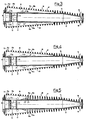
- FIGS. 3, 4 and 5 there are illustrated three further variants, respectively, of a scroll according to the invention.
- the baffles 20 in order to render the level of the liquid phase, particularly the oil, uniform in all the compartments 21, the baffles 20 have one or more passages at their radially inner parts, near the attachment to the tubular hub 14.
- the radially inner edges 24 of the baffles 20 are so shaped as to define with the tubular hub 14 one or more slits 23a setting adjacent compartments in direct fluid communication.
- the passages are formed by a plurality of recesses 23b formed in the radially inner edges 24 of the baffles.
- said passages are provided by bores 23c obtained adjacent to the hub 14.
- the baffles have a reduced axial dimension and terminate at the right side forming an acute extension 25 determining a further passage zone 26 with the hub that helps in levelling the liquid phase uniformly.
Landscapes
- Centrifugal Separators (AREA)
- Extraction Or Liquid Replacement (AREA)
Abstract
Description
- FIG. 1
- is an axial sectional view of a first embodiment of an inner scroll for a centrifugal separator in accordance with the present invention;
- FIG. 2
- is a radial cross sectional view taken along the line II-II of FIG. 1; and
- FIGS. 3, 4 and 5
- are axial cross sectional views, to a smaller scale, of three further embodiments, respectively, of baffles which the scroll of the invention is fitted with.
Claims (10)
- A rotating inner scroll (10) for a centrifugal separator with a horizontal axis for separating the liquid and solid phases from a past of crushed olives, the scroll comprising an elongated central hub (14) of substantially tubular shape and an outer drum of substantially truncated cone shape, characterised by comprising at least one baffle (20) oriented in an axial plane, said at least one baffle radially extending between the tubular hub (14) and the drum so as to form at least one barrier encompassing at least the boundary zone (A) between the oil and the water being separated by centrifugation.
- A scroll as claimed in claim 1, characterised in that said at least one barrier encompasses both the boundary zones (A, B) between the liquid and solid phases separated by centrifugation.
- A scroll as claimed in claim 1 or 2, characterised by comprising a plurality of axial baffles (20) oriented according to axial planes angularly spaced around the tubular hub (14) and forming a plurality of said barriers.
- A scroll as claimed in claim 3, characterised in that the radially outer edges (22) of said baffles (20) are fixed to at least one spiral (15) disposed around the peripheral part of the scroll (10).
- A scroll as claimed in claim 4, characterised in that the radially outer edges (22) of said baffles (20) are spaced apart from said drum so as to define with said spiral and said drum at least one peripheral helical channel (17) of substantially constant cross section.
- A scroll as claimed in claim 1, characterised in that the axial length of said at least one baffle (20) is limited to the length of the scroll (10) where the liquid phases are present.
- A scroll as claimed in claim 3, characterised in that said baffles are angularly equally spaced.
- A scroll as claimed in claim 3, characterised in that said baffles (20) define a corresponding plurality of compartments (21) open in radially outer directions.
- A scroll as claimed in claim 8, characterised in that each compartment (21) is limited laterally by two consecutive baffles (20), and at the radially inner side by the cylindrical outer surface of said tubular hub.
- A scroll as claimed in claim 9, characterised in that said baffles (20) form one or more passages (23a, 23b, 23c, 26) in their radially inner zone, said passages setting the liquid present in adjacent compartments (21) in direct fluid communication.
Applications Claiming Priority (2)
| Application Number | Priority Date | Filing Date | Title |
|---|---|---|---|
| ITTO960990 | 1996-12-05 | ||
| ITTO960990 IT1289718B1 (en) | 1996-12-05 | 1996-12-05 | ROTATING DRUM WITH INTERNAL AUGER FOR CENTRIFUGAL EXTRACTOR FOR OLIVE OIL |
Publications (3)
| Publication Number | Publication Date |
|---|---|
| EP0856360A2 true EP0856360A2 (en) | 1998-08-05 |
| EP0856360A3 EP0856360A3 (en) | 1999-02-03 |
| EP0856360B1 EP0856360B1 (en) | 2002-09-04 |
Family
ID=11415083
Family Applications (1)
| Application Number | Title | Priority Date | Filing Date |
|---|---|---|---|
| EP19970121247 Expired - Lifetime EP0856360B1 (en) | 1996-12-05 | 1997-12-03 | An inner scroll for an olive oil centrifugal separator |
Country Status (3)
| Country | Link |
|---|---|
| EP (1) | EP0856360B1 (en) |
| ES (1) | ES2181975T3 (en) |
| IT (1) | IT1289718B1 (en) |
Cited By (5)
| Publication number | Priority date | Publication date | Assignee | Title |
|---|---|---|---|---|
| WO2001051165A1 (en) * | 2000-01-11 | 2001-07-19 | Dr. Frische Gmbh | Decanter for separating two liquid phases having different densities |
| ES2178543A1 (en) * | 1999-04-06 | 2002-12-16 | Nuova Maip Macchine Agric | Procedure for the obtaining of oil from products that produce oil such as olives and similar, through spin with the separation of the solid component in two parts, and corresponding installation. (Machine-translation by Google Translate, not legally binding) |
| WO2011144520A1 (en) | 2010-05-18 | 2011-11-24 | Gea Mechanical Equipment Gmbh | Solid bowl screw centrifuge |
| CN102489416A (en) * | 2011-11-23 | 2012-06-13 | 江南大学 | Internal-circulation horizontal spiral centrifuge |
| CN103657880A (en) * | 2013-12-18 | 2014-03-26 | 山东博润工业技术股份有限公司 | Split type screen sedimentation centrifuge spiral conveyor |
Families Citing this family (1)
| Publication number | Priority date | Publication date | Assignee | Title |
|---|---|---|---|---|
| ITMI20070345A1 (en) * | 2007-02-22 | 2008-08-23 | Nuova Maip Macchine Agricole Industriali | PROCEDURE AND EQUIPMENT FOR THE SEPARATION AND EXTRACTION OF DIFFERENT OLEAGINOSE AND SIMILAR PASTE PRODUCTS |
Family Cites Families (5)
| Publication number | Priority date | Publication date | Assignee | Title |
|---|---|---|---|---|
| US2578456A (en) * | 1946-07-31 | 1951-12-11 | Centrifuge Mechanical Equipmen | Centrifugal separator |
| FR2449467A1 (en) * | 1979-02-23 | 1980-09-19 | Saget Pierre | IMPROVED METHOD AND APPARATUS USING THE SAME FOR CENTRIFUGAL SEPARATION OF AT LEAST TWO LIQUID PHASES FROM A MIXTURE |
| DE2907318A1 (en) * | 1979-02-24 | 1980-08-28 | Bayer Ag | Centrifuge drum with cylindrical and conical zones - where worm profile is designed for efficient sepn. of solids from liquids, esp. from liquids with high viscosity |
| US4743226A (en) * | 1983-04-29 | 1988-05-10 | Geosource Inc. | High capacity continuous solid bowl centrifuge |
| US5354255A (en) * | 1992-12-17 | 1994-10-11 | Alfa Laval Separation Inc. | Decanter centrifuge with conveyor capable of high speed and higher flow rates |
-
1996
- 1996-12-05 IT ITTO960990 patent/IT1289718B1/en active IP Right Grant
-
1997
- 1997-12-03 EP EP19970121247 patent/EP0856360B1/en not_active Expired - Lifetime
- 1997-12-03 ES ES97121247T patent/ES2181975T3/en not_active Expired - Lifetime
Cited By (7)
| Publication number | Priority date | Publication date | Assignee | Title |
|---|---|---|---|---|
| ES2178543A1 (en) * | 1999-04-06 | 2002-12-16 | Nuova Maip Macchine Agric | Procedure for the obtaining of oil from products that produce oil such as olives and similar, through spin with the separation of the solid component in two parts, and corresponding installation. (Machine-translation by Google Translate, not legally binding) |
| WO2001051165A1 (en) * | 2000-01-11 | 2001-07-19 | Dr. Frische Gmbh | Decanter for separating two liquid phases having different densities |
| WO2011144520A1 (en) | 2010-05-18 | 2011-11-24 | Gea Mechanical Equipment Gmbh | Solid bowl screw centrifuge |
| DE102010020901A1 (en) * | 2010-05-18 | 2011-11-24 | Gea Mechanical Equipment Gmbh | Solid bowl centrifuge |
| CN102489416A (en) * | 2011-11-23 | 2012-06-13 | 江南大学 | Internal-circulation horizontal spiral centrifuge |
| CN103657880A (en) * | 2013-12-18 | 2014-03-26 | 山东博润工业技术股份有限公司 | Split type screen sedimentation centrifuge spiral conveyor |
| CN103657880B (en) * | 2013-12-18 | 2016-08-31 | 山东博润工业技术股份有限公司 | Split type screen sedimentation centrifuge spiral conveyor |
Also Published As
| Publication number | Publication date |
|---|---|
| ITTO960990A1 (en) | 1998-06-05 |
| IT1289718B1 (en) | 1998-10-16 |
| EP0856360A3 (en) | 1999-02-03 |
| ES2181975T3 (en) | 2003-03-01 |
| EP0856360B1 (en) | 2002-09-04 |
Similar Documents
| Publication | Publication Date | Title |
|---|---|---|
| CA2092980C (en) | Decanter centrifuge for thickening at high rates | |
| US5840006A (en) | Feed accelerator system including accelerating vane apparatus | |
| US3623656A (en) | Three-phase centrifuge | |
| US4245777A (en) | Centrifuge apparatus | |
| CN1028612C (en) | Centrifugal separator | |
| JPS6018457B2 (en) | centrifuge | |
| SE459559B (en) | CONTINUOUS WORKING WHOLESALE COATED countercurrent centrifugal extractor | |
| US6030332A (en) | Centrifuge system with stacked discs attached to the housing | |
| US6908423B2 (en) | Screw for a solid-bowl centrifuge and a method of extracting oil using the centrifuge | |
| JP2017006909A (en) | Decanter type centrifugal separator | |
| EP0856360B1 (en) | An inner scroll for an olive oil centrifugal separator | |
| CN211275038U (en) | Disc type separator | |
| US6533713B1 (en) | Entraining device for a centrifugal separator | |
| EP0068869A2 (en) | A centrifuge with a skimmer disc for discharging a liquid phase | |
| JP4226036B2 (en) | Screw conveyor for decanter type centrifuge | |
| US4863605A (en) | Hydrocyclone with parallel rotor vanes and annular ring members | |
| CN112916216A (en) | Disc type separator | |
| GB2083381A (en) | Uniflow decanter centrifuge | |
| HU209077B (en) | Method and apparatus for separating materials from media | |
| US3499602A (en) | Centrifugal separator | |
| EP0824379B1 (en) | Centrifugal separator | |
| CN112916215B (en) | Sealing structure of disc separator | |
| EP1058585B1 (en) | A centrifugal separator | |
| US3998382A (en) | Mechanism for degasification of a viscous liquid by means of centrifugal action | |
| CA1143370A (en) | Contactor |
Legal Events
| Date | Code | Title | Description |
|---|---|---|---|
| PUAI | Public reference made under article 153(3) epc to a published international application that has entered the european phase |
Free format text: ORIGINAL CODE: 0009012 |
|
| AK | Designated contracting states |
Kind code of ref document: A2 Designated state(s): ES FR GR IT PT |
|
| AX | Request for extension of the european patent |
Free format text: AL;LT;LV;MK;RO;SI |
|
| PUAL | Search report despatched |
Free format text: ORIGINAL CODE: 0009013 |
|
| AK | Designated contracting states |
Kind code of ref document: A3 Designated state(s): AT BE CH DE DK ES FI FR GB GR IE IT LI LU MC NL PT SE |
|
| AX | Request for extension of the european patent |
Free format text: AL;LT;LV;MK;RO;SI |
|
| 17P | Request for examination filed |
Effective date: 19990803 |
|
| AKX | Designation fees paid |
Free format text: CH ES FR GR IT LI |
|
| AXX | Extension fees paid |
Free format text: AL PAYMENT 19990803 |
|
| RBV | Designated contracting states (corrected) |
Designated state(s): ES FR GR IT PT |
|
| REG | Reference to a national code |
Ref country code: DE Ref legal event code: 8566 |
|
| 17Q | First examination report despatched |
Effective date: 20010515 |
|
| GRAG | Despatch of communication of intention to grant |
Free format text: ORIGINAL CODE: EPIDOS AGRA |
|
| GRAG | Despatch of communication of intention to grant |
Free format text: ORIGINAL CODE: EPIDOS AGRA |
|
| GRAH | Despatch of communication of intention to grant a patent |
Free format text: ORIGINAL CODE: EPIDOS IGRA |
|
| GRAH | Despatch of communication of intention to grant a patent |
Free format text: ORIGINAL CODE: EPIDOS IGRA |
|
| GRAA | (expected) grant |
Free format text: ORIGINAL CODE: 0009210 |
|
| AK | Designated contracting states |
Kind code of ref document: B1 Designated state(s): ES FR GR IT PT |
|
| AX | Request for extension of the european patent |
Free format text: AL PAYMENT 19990803 |
|
| PG25 | Lapsed in a contracting state [announced via postgrant information from national office to epo] |
Ref country code: FR Free format text: LAPSE BECAUSE OF FAILURE TO SUBMIT A TRANSLATION OF THE DESCRIPTION OR TO PAY THE FEE WITHIN THE PRESCRIBED TIME-LIMIT Effective date: 20020904 |
|
| PG25 | Lapsed in a contracting state [announced via postgrant information from national office to epo] |
Ref country code: PT Free format text: LAPSE BECAUSE OF FAILURE TO SUBMIT A TRANSLATION OF THE DESCRIPTION OR TO PAY THE FEE WITHIN THE PRESCRIBED TIME-LIMIT Effective date: 20021213 |
|
| REG | Reference to a national code |
Ref country code: GR Ref legal event code: EP Ref document number: 20020403953 Country of ref document: GR |
|
| REG | Reference to a national code |
Ref country code: ES Ref legal event code: FG2A Ref document number: 2181975 Country of ref document: ES Kind code of ref document: T3 |
|
| EN | Fr: translation not filed | ||
| PLBE | No opposition filed within time limit |
Free format text: ORIGINAL CODE: 0009261 |
|
| STAA | Information on the status of an ep patent application or granted ep patent |
Free format text: STATUS: NO OPPOSITION FILED WITHIN TIME LIMIT |
|
| 26N | No opposition filed |
Effective date: 20030605 |
|
| PGFP | Annual fee paid to national office [announced via postgrant information from national office to epo] |
Ref country code: ES Payment date: 20090120 Year of fee payment: 12 |
|
| PGFP | Annual fee paid to national office [announced via postgrant information from national office to epo] |
Ref country code: GR Payment date: 20081113 Year of fee payment: 12 |
|
| REG | Reference to a national code |
Ref country code: ES Ref legal event code: FD2A Effective date: 20110329 |
|
| PG25 | Lapsed in a contracting state [announced via postgrant information from national office to epo] |
Ref country code: ES Free format text: LAPSE BECAUSE OF NON-PAYMENT OF DUE FEES Effective date: 20110316 |
|
| PGFP | Annual fee paid to national office [announced via postgrant information from national office to epo] |
Ref country code: IT Payment date: 20081215 Year of fee payment: 12 |
|
| PGRI | Patent reinstated in contracting state [announced from national office to epo] |
Ref country code: IT Effective date: 20110616 |
|
| PG25 | Lapsed in a contracting state [announced via postgrant information from national office to epo] |
Ref country code: ES Free format text: LAPSE BECAUSE OF NON-PAYMENT OF DUE FEES Effective date: 20091204 |
|
| PGRI | Patent reinstated in contracting state [announced from national office to epo] |
Ref country code: IT Effective date: 20110616 |