EP0857929B1 - Kältegerät zum Einbau in eine Möbelnische - Google Patents
Kältegerät zum Einbau in eine Möbelnische Download PDFInfo
- Publication number
- EP0857929B1 EP0857929B1 EP98100743A EP98100743A EP0857929B1 EP 0857929 B1 EP0857929 B1 EP 0857929B1 EP 98100743 A EP98100743 A EP 98100743A EP 98100743 A EP98100743 A EP 98100743A EP 0857929 B1 EP0857929 B1 EP 0857929B1
- Authority
- EP
- European Patent Office
- Prior art keywords
- slide block
- cooling appliance
- guide
- furniture
- slide
- Prior art date
- Legal status (The legal status is an assumption and is not a legal conclusion. Google has not performed a legal analysis and makes no representation as to the accuracy of the status listed.)
- Expired - Lifetime
Links
- 238000009434 installation Methods 0.000 claims description 5
- 238000001816 cooling Methods 0.000 claims 10
- 238000005057 refrigeration Methods 0.000 description 4
- 239000000243 solution Substances 0.000 description 3
- 239000002131 composite material Substances 0.000 description 2
- 238000006073 displacement reaction Methods 0.000 description 2
- 238000002347 injection Methods 0.000 description 2
- 239000007924 injection Substances 0.000 description 2
- 238000010276 construction Methods 0.000 description 1
- 238000005516 engineering process Methods 0.000 description 1
- 230000006870 function Effects 0.000 description 1
- 238000001746 injection moulding Methods 0.000 description 1
- 230000008407 joint function Effects 0.000 description 1
- 238000005259 measurement Methods 0.000 description 1
- 238000000034 method Methods 0.000 description 1
- 239000002991 molded plastic Substances 0.000 description 1
- 239000004033 plastic Substances 0.000 description 1
Images

Classifications
-
- F—MECHANICAL ENGINEERING; LIGHTING; HEATING; WEAPONS; BLASTING
- F25—REFRIGERATION OR COOLING; COMBINED HEATING AND REFRIGERATION SYSTEMS; HEAT PUMP SYSTEMS; MANUFACTURE OR STORAGE OF ICE; LIQUEFACTION SOLIDIFICATION OF GASES
- F25D—REFRIGERATORS; COLD ROOMS; ICE-BOXES; COOLING OR FREEZING APPARATUS NOT OTHERWISE PROVIDED FOR
- F25D23/00—General constructional features
- F25D23/10—Arrangements for mounting in particular locations, e.g. for built-in type, for corner type
-
- F—MECHANICAL ENGINEERING; LIGHTING; HEATING; WEAPONS; BLASTING
- F25—REFRIGERATION OR COOLING; COMBINED HEATING AND REFRIGERATION SYSTEMS; HEAT PUMP SYSTEMS; MANUFACTURE OR STORAGE OF ICE; LIQUEFACTION SOLIDIFICATION OF GASES
- F25D—REFRIGERATORS; COLD ROOMS; ICE-BOXES; COOLING OR FREEZING APPARATUS NOT OTHERWISE PROVIDED FOR
- F25D23/00—General constructional features
- F25D23/02—Doors; Covers
- F25D23/028—Details
-
- A—HUMAN NECESSITIES
- A47—FURNITURE; DOMESTIC ARTICLES OR APPLIANCES; COFFEE MILLS; SPICE MILLS; SUCTION CLEANERS IN GENERAL
- A47B—TABLES; DESKS; OFFICE FURNITURE; CABINETS; DRAWERS; GENERAL DETAILS OF FURNITURE
- A47B96/00—Details of cabinets, racks or shelf units not covered by a single one of groups A47B43/00 - A47B95/00; General details of furniture
- A47B96/20—Furniture panels or like furniture elements
- A47B2096/208—Decorative panels for household appliances
Definitions
- the invention relates to a refrigerator for installation in a niche in a kitchen or for installation in a space between two furniture niches or the like, with a on the front of the refrigerator door, which is arranged with the front of the Refrigerator door is hinged on the opening side via at least one sliding joint, which has a guide and a sliding block (see e.g. DE-U-75 20 916).
- furniture front panels can also be installed Furniture front panels application that is outside the vertical axis of rotation of the refrigerator door are pivotally mounted in a separate vertical axis of rotation and which with the Refrigerator door through two sliding joints arranged vertically one above the other are movably connected to the necessary relative movement between the furniture front panel and to allow the refrigerator door via an opening and closing operation of the latter.
- the slide In order to avoid this problem, it was proposed to use the slide with a brand to serve the pointed notch, the tip of which is when the refrigerator door is opened by 90 ° must be in alignment with the vertical opening-side cheek of the door to the to ensure the slide is in the correct position.
- This type of correct position finding for the slide requires a sensitive adjustment to this side wall with the To bring the brand into cover.
- the measuring mark is on Align the slide on the refrigerator door while the slide itself on the furniture front panel is attached, so that the positioning and attachment process of the slide due to the different articulation points of the furniture front panel and refrigerator door and the resulting possibility of a relative movement between the two clearly is difficult.
- the invention is based, with a refrigerator according to the preamble of the task Claim 1 with simple design measures the disadvantages of the prior art Avoid technology.
- the sliding block or the guide of the thrust joint has at least one stop element, the stop surface of which essentially is arranged perpendicular to the direction of displacement of the sliding block and as a depth limit to determine the return of the sliding block or the guide from the vertical Sidewall of the furniture front panel is used.
- the solution according to the invention is the slider serving as a sliding block or the guide designed as a setting gauge, which is directly on the corresponding side cheek the furniture front panel used to fasten the slide or the guide can be put on is so that the determination of the mounting position of the slide or the guide on the Furniture faceplate can be done with high accuracy because both additional, the appearance measuring equipment that enables measurement errors as well as indirect definition of the mounting location is avoided via the refrigerator door.
- the slide or the guide on the furniture front panel is not only the assembly a single assembly person possible, but also with a low amount of work Can be carried out precisely.
- stop element and the sliding block or the guide at least via a connecting web are interconnected.
- the stop element is after fastening the sliding block or the guide on the furniture front panel, for example with the help of a cutting tool can be removed quickly and with little effort.
- the slider which serves as a sliding block, is particularly easy and precisely lockable of the pusher joint on the furniture front panel in a refrigerator with its refrigerator fixable for fixed guidance and sliding block attached to its furniture front plate, if according to a next preferred embodiment of the subject of the invention it is provided that the stop element with the sliding block at its with mounting receptacles for fixing to the section on the furniture door via the connecting bridge connected is.
- the stop element is particularly robust and easy to handle of the sliding block designed as a setting gauge, if according to a next advantageous embodiment the subject of the invention it is provided that the stop element as Angle profile is formed, which with one of its legs via at least one connecting web is connected to the sliding block and which one on its other leg Has stop surface which is substantially perpendicular to the direction of displacement of the Sliding block is arranged.
- leg of the leg profile provided with the stop surface provided on its outside opposite the stop surface with the sliding joint guide is, while the leg connected to the sliding block mounting holes having.
- a refrigerator door is connected to the furniture front panel Slide joint provided, which in addition to their joint functions also as Setting gauge serves. Due to the construction of the angle profile in combination with it Connection to the sliding block serving as a slide arises in the event that the Arrangement made of injection molded plastic, a particularly inexpensive tool design, in which additional side shifters to the injection mold can be omitted, because both the mounting holes for the slide and those for the angle profile as the guides for the sliding block also have the same direction of removal,
- the sliding block is provided with at least two cover elements, which can cover the mounting holes on the sliding block and those on the angle profile and which are connected to the sliding block at least via a connecting web are.
- the angle profile with the arranged on it can be particularly effortless and therefore easy to assemble Sliding joint guide and the cover elements from the sliding block in case of assembly separate if according to a last preferred embodiment of the object of Invention is provided that the connecting webs are designed like a film hinge and have a predetermined breaking point.
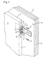
- FIG 1 is a drawn in a highly simplified representation, not shown
- Refrigerator such as a refrigerator door belonging to a domestic refrigerator or freezer 10 shown, which on its opening-side vertical side cheek 11 in the vicinity of its upper horizontal cheek each two vertically spaced one above the other Has receiving holes 12 and which on their from the interior of the refrigerator facing away from the outside 13 is a furniture front panel 14.
- the furniture front panel 14 is on not shown, arranged separately to the pivot bearings of the refrigerator door Pivots pivotable about a vertical axis of rotation and which in the close range of their Pivoting opposite side cheek 15 on its front side 13 opposite inner side 16 by two spaced one above the other Sliding joints 17 (only one of which is shown), which are adjacent to the horizontal Sidewalls of the furniture front panel 14 are arranged with the refrigerator door 10 movable connected is.
- the sliding joints 17 consist of one in the side cheek 11 fixed angle profile 18 with two substantially perpendicular to each other Legs together, on which one leg as a fastening leg 19 with two in height the receiving holes 12 arranged through holes 20 is, in which two mounting holes 21 can be introduced, which for fixing the Angle profile 18 on the side cheek 11 to cooperate with the receiving holes 12 capital.
- the angle profile 18 is on its second, from the mounting leg 19 in legs 22 branching essentially at right angles, on the leg of which the furniture front plate 14 facing outer sides with a guide 24, which by two in vertical Distance arranged one above the other, with their free ends facing each other 25 and the outside 23 is formed.
- the leg 22 is in the attached state of the angle profile 18 on the side cheek 11 with its opposite the outside 23, serving as the stop surface 26 on the inside of the front 13.
- a slide serving as a sliding block of the sliding joint 17 27 slidably in the horizontal direction, which with its side cheek 15th facing sections of the furniture front panel 14 is fixed.
- the depth dimension t is used to determine which the end face of the slide 27 facing the side cheek 15 may be set back must, a partial composite between the slide 27 and the angle profile 18.
- the angle profile 18 is for this purpose with its mounting leg 19 over two at a vertical distance mutually arranged film hinge-like connecting webs 28 with the slide 27 connected.
- To mark and fix the position of the slide 27 with respect to the Side cheek 15 becomes the inside of leg 22 serving as stop surface 26 Bring plant with the side cheek 15 of the furniture front panel 14.
- By creating the stop surface 26 is the depth dimension t by which the free side facing the side wall 15 End of the slide opposite the side wall 15 for the proper function of the Push joint 17 must be fixed on the inside 16, automatically specified.
- elongated holes 33 in cross section intended.
- screw-in mounting holes 31 are provided, which by their stepped Training can accommodate the screw head of the mounting screws.
- the Fastening screws 31 are in the by a not shown notches Receptacle 29 fixable cover element 32, which in the receptacle 29th inserted state with its outside facing the front 13 flush ends with the outside of the slide 27 on this side.
- the cover member 32 is like the angle profile 18 and a further cover element 33 each having a film hinge-like Connecting web 34 connected to the slide 27 and in one operation produced together with this in the plastic injection molding process.
- the further Cover element 33 is therefor as a cover for fixing the angle profile 18 to the Side cheek 11 serving fastening screws 21 are provided.
Landscapes
- Engineering & Computer Science (AREA)
- Chemical & Material Sciences (AREA)
- Combustion & Propulsion (AREA)
- Physics & Mathematics (AREA)
- Mechanical Engineering (AREA)
- Thermal Sciences (AREA)
- General Engineering & Computer Science (AREA)
- Refrigerator Housings (AREA)
- Cabinets, Racks, Or The Like Of Rigid Construction (AREA)
- Hinges (AREA)
Description
- Fig. 1
- ausschnittsweise den oberen Abschnitt einer vereinfacht dargestellten Kältegerätetür mit einer vorgesetzten, über ein Schubgelenk mit der Kältegerätetür beweglich verbundenen Möbelfrontplatte, in raumbildlicher Ansicht von der Seite,
- Fig. 2
- ausschnittsweise den oberen Abschnitt der Kältegerätetür mit der Möbelfrontplatte, an welcher mit Hilfe des als Einstelllehre dienenden Teileverbundes zwischen den Schieber und der Schieberführung des Schubgelenks die Befestigungsposition des Schiebers an der Möbelfrontplatte festgelegt ist, in raumbildlicher Ansicht von der Seite, und
- Fig. 3
- einen Verbund von Einzelteilen zur Zusammenfügung und Montage des Schubgelenks an der Kältegerätetür bzw. an der Möbelfrontplatte, in raumbildlicher Ansicht von vorne.
Claims (7)
- Kältegerät zum Einbau in eine Möbelnische einer Küchenzeile oder zum Einbau in einen Zwischenraum zwischen zwei Möbelnischen oder dergleichen, mit einer frontseitig an der Kältegerätetür (10) angeordneten Möbelfrontplatte (14), welche mit der Frontseite der Kältegerätetür an deren Öffnungsseite über zumindest ein Schubgelenk (17) verbunden ist, welches eine Führung (24) und einen Gleitstein (27) aufweist, dadurch gekennzeichnet, daß der Gleitstein (27) oder die Führung (24) des Schubgelenkes (17) wenigstens ein Anschlagelement (18) aufweist, dessen Anschlagfläche (26) im wesentlichen senkrecht zur Schieberichtung des Gleitsteines (27) angeordnet ist und während der Montage als Tiefenbegrenzung zur Festlegung des Rücksprungs (t) des Gleitsteines (27) oder der Führung (24) von der vertikalen Seitenwange (15) der Möbelfrontplatte (14) dient.
- Kältegerät nach Anspruch 1, dadurch gekennzeichnet, daß das Anschlagelement (18) und der Gleitstein (27) oder die Führung (24) wenigstens über einen Verbindungssteg (28) verbunden sind.
- Kältegerät mit an dessen Kältegerätetür (10) festgesetzter Führung und an dessen Möbelfrontplatte (14) befestigtem Gleitstein nach Anspruch 2, dadurch gekennzeichnet, daß das Anschlagelement (18) mit dem Gleitstein (27) an dessen mit Befestigungsaufnahmen (30) zur Festsetzung an der Möbelfrontplatte (14) versehenen Abschnitt über den Verbindungssteg (28) verbunden ist.
- Kältegerät nach einem der Ansprüche 1 - 3, dadurch gekennzeichnet, daß das Anschlagelement als Winkelprofil (18) ausgebildet ist, welches mit einem seiner Schenkel (19) über zumindest einen Verbindungssteg (28) mit dem Gleitstein (27) verbunden ist und welches an seinem anderen Schenkel (22) die Anschlagfläche (26) aufweist.
- Kältegerät nach Anspruch 4, dadurch gekennzeichnet, daß der mit der Anschlagfläche (26) versehene Schenkel (22) des Winkelprofils (18) auf seiner der Anschlagfläche (26) gegenüberliegenden Außenseite (23) mit der Schubgelenkführung (24) versehen ist, während der mit dem Gleitstein (27) verbundene Schenkel (19) Befestigungsbohrungen (20) aufweist.
- Kältegerät nach einem der Ansprüche 1 - 5, dadurch gekennzeichnet, daß der Gleitstein (27) mit zumindest zwei Abdeckelementen (32, 33) versehen ist, welche Befestigungsbohrungen (20, 30) am Gleitstein (27) und am Winkelprofil (18) abzudecken vermögen und welche wenigstens über je einen Verbindungssteg (34) mit dem Gleitstein (27) verbunden sind.
- Kältegerät nach einem der Ansprüche 4 oder 6, dadurch gekennzeichnet, daß die Verbindungsstege (28, 34) filmscharnierartig ausgebildet sind und eine Sollbruchstelle aufweisen.
Priority Applications (1)
| Application Number | Priority Date | Filing Date | Title |
|---|---|---|---|
| SI9830092T SI0857929T1 (en) | 1997-02-07 | 1998-01-16 | Refrigerator to be built in a furniture recess |
Applications Claiming Priority (2)
| Application Number | Priority Date | Filing Date | Title |
|---|---|---|---|
| DE19704698 | 1997-02-07 | ||
| DE19704698A DE19704698A1 (de) | 1997-02-07 | 1997-02-07 | Kältegerät zum Einbau in eine Möbelnische |
Publications (2)
| Publication Number | Publication Date |
|---|---|
| EP0857929A1 EP0857929A1 (de) | 1998-08-12 |
| EP0857929B1 true EP0857929B1 (de) | 2002-05-15 |
Family
ID=7819621
Family Applications (1)
| Application Number | Title | Priority Date | Filing Date |
|---|---|---|---|
| EP98100743A Expired - Lifetime EP0857929B1 (de) | 1997-02-07 | 1998-01-16 | Kältegerät zum Einbau in eine Möbelnische |
Country Status (5)
| Country | Link |
|---|---|
| EP (1) | EP0857929B1 (de) |
| DE (2) | DE19704698A1 (de) |
| ES (1) | ES2176823T3 (de) |
| SI (1) | SI0857929T1 (de) |
| TR (1) | TR199800180A3 (de) |
Cited By (3)
| Publication number | Priority date | Publication date | Assignee | Title |
|---|---|---|---|---|
| EP2664879A2 (de) | 2012-05-16 | 2013-11-20 | BSH Bosch und Siemens Hausgeräte GmbH | Vorrichtung zum Positionieren eines Befestigungselements sowie ein Verfahren zur Montage eines Befestigungselements an einer Möbelfront |
| DE102012208260A1 (de) | 2012-05-16 | 2013-11-21 | BSH Bosch und Siemens Hausgeräte GmbH | Vorrichtung zum Positionieren eines Befestigungselements sowie ein Verfahren zur Montage eines Befestigungselements an einer Möbelfront |
| US11635248B2 (en) | 2021-06-18 | 2023-04-25 | Whirlpool Corporation | Built-in refrigerator |
Families Citing this family (12)
| Publication number | Priority date | Publication date | Assignee | Title |
|---|---|---|---|---|
| SE520946C2 (sv) * | 2002-01-18 | 2003-09-16 | Electrolux Home Prod Corp | Skåpinbyggnadsarrangemang för en hushållsmaskin, exv. en diskmaskin |
| DE102005021607A1 (de) | 2005-05-10 | 2006-11-23 | BSH Bosch und Siemens Hausgeräte GmbH | Tür für ein Haushaltsgerät |
| DE102007021554A1 (de) * | 2007-05-08 | 2008-11-13 | BSH Bosch und Siemens Hausgeräte GmbH | Haushaltsgerät |
| ITTO20100119A1 (it) * | 2010-02-17 | 2011-08-18 | Indesit Co Spa | Dispositivo di afferraggio per uno sportello di un elettrodomestico, ed elettrodomestico provvisto di tale dispositivo |
| DE102011007410A1 (de) * | 2011-04-14 | 2012-10-18 | BSH Bosch und Siemens Hausgeräte GmbH | Einbau-Kältegrät mit einem Beschlagsbauteil |
| ITVA20120038A1 (it) * | 2012-10-18 | 2014-04-19 | Whirlpool Co | Sistema di montaggio di pannelli su porte di frigoriferi da incasso |
| DE102014100846A1 (de) | 2014-01-24 | 2015-07-30 | Hettich-Oni Gmbh & Co. Kg | Verfahren und Montagehilfswerkzeug zum Montieren eines Schlepptürbeschlags |
| DE102014225088B4 (de) | 2014-12-08 | 2025-05-28 | BSH Hausgeräte GmbH | Verfahren zum Montieren einer Schleppvorrichtung |
| CN106839620B (zh) * | 2017-01-18 | 2019-10-01 | 合肥华凌股份有限公司 | 嵌入式冰箱的门连接装置及嵌入式冰箱装置 |
| EP3789705B1 (de) * | 2019-09-05 | 2022-08-17 | Electrolux Appliances Aktiebolag | Montagewerkzeug für ein verbindungssystem einer tür eines eingebauten haushaltsgerätes mit einer tür eines möbelstücks |
| EP3889527B1 (de) | 2020-04-01 | 2023-05-31 | Whirlpool Corporation | Einbauanordnung mit einem kühlgerät und einem möbel |
| US20230296307A1 (en) * | 2022-03-18 | 2023-09-21 | Whirlpool Corporation | Slide mechanism for a built-in refrigerator |
Family Cites Families (4)
| Publication number | Priority date | Publication date | Assignee | Title |
|---|---|---|---|---|
| DE7334526U (de) * | 1973-09-24 | 1977-09-08 | Licentia Patent-Verwaltungs-Gmbh, 6000 Frankfurt | Kühlschranktür |
| DE7520916U (de) * | 1975-07-02 | 1975-11-06 | Licentia Gmbh | |
| FR2671467B1 (fr) * | 1991-01-11 | 1993-06-18 | Dietrich Equip Menager | Interface de rattrapage du deport lateral entre la porte d'un appareil electromenager et celle du meuble-element qui le contient. |
| DE29512600U1 (de) * | 1995-08-04 | 1996-11-28 | AEG Hausgeräte GmbH, 90429 Nürnberg | Befestigungselement für ein Hausgerät |
-
1997
- 1997-02-07 DE DE19704698A patent/DE19704698A1/de not_active Withdrawn
-
1998
- 1998-01-16 EP EP98100743A patent/EP0857929B1/de not_active Expired - Lifetime
- 1998-01-16 ES ES98100743T patent/ES2176823T3/es not_active Expired - Lifetime
- 1998-01-16 DE DE59804107T patent/DE59804107D1/de not_active Expired - Lifetime
- 1998-01-16 SI SI9830092T patent/SI0857929T1/xx unknown
- 1998-02-06 TR TR1998/00180A patent/TR199800180A3/tr unknown
Cited By (5)
| Publication number | Priority date | Publication date | Assignee | Title |
|---|---|---|---|---|
| EP2664879A2 (de) | 2012-05-16 | 2013-11-20 | BSH Bosch und Siemens Hausgeräte GmbH | Vorrichtung zum Positionieren eines Befestigungselements sowie ein Verfahren zur Montage eines Befestigungselements an einer Möbelfront |
| DE102012208258A1 (de) | 2012-05-16 | 2013-11-21 | BSH Bosch und Siemens Hausgeräte GmbH | Vorrichtung zum Positionieren eines Befestigungselements sowie ein Verfahren zur Montage eines Befestigungselements an einer Möbelfront |
| DE102012208260A1 (de) | 2012-05-16 | 2013-11-21 | BSH Bosch und Siemens Hausgeräte GmbH | Vorrichtung zum Positionieren eines Befestigungselements sowie ein Verfahren zur Montage eines Befestigungselements an einer Möbelfront |
| US11635248B2 (en) | 2021-06-18 | 2023-04-25 | Whirlpool Corporation | Built-in refrigerator |
| US11927385B2 (en) | 2021-06-18 | 2024-03-12 | Whirlpool Corporation | Built-in refrigerator |
Also Published As
| Publication number | Publication date |
|---|---|
| ES2176823T3 (es) | 2002-12-01 |
| DE59804107D1 (de) | 2002-06-20 |
| DE19704698A1 (de) | 1998-08-13 |
| SI0857929T1 (en) | 2002-08-31 |
| TR199800180A2 (xx) | 1998-08-21 |
| TR199800180A3 (tr) | 1998-08-21 |
| EP0857929A1 (de) | 1998-08-12 |
Similar Documents
| Publication | Publication Date | Title |
|---|---|---|
| EP0857929B1 (de) | Kältegerät zum Einbau in eine Möbelnische | |
| EP2012619B1 (de) | Unterflur-führungsanordnung für möbelteile, insbesondere schubladen im korpus von möbelstücken | |
| EP3346074B1 (de) | Montagevorrichtung zum einsetzen von rahmenelementen in wandöffnungen | |
| DE2404575A1 (de) | Schliessvorrichtung fuer eine tuer | |
| DE8010921U1 (de) | Scharnierbandverbindung fuer fenster, tueren und tore | |
| DE3338943A1 (de) | Bohr-lehrenvorrichtung fuer moebelbeschlagteile | |
| DE2038990C3 (de) | Ausstellvorrichtung für kipp- oder schwenkbare Flügel | |
| DE9011467U1 (de) | Gerät zum Anbringen der Bohrungen zum Befestigen der Rahmenbandteile eines Fensters oder einer Türe | |
| DE19602025C2 (de) | Verfahren zum Herstellen eines Flügelrahmens für ein Fenster oder eine Tür, sowie Schubstangenbeschlag zur Verwendung für das Verfahren | |
| DE10039560C2 (de) | Vorrichtung für das Betätigen eines Fensters | |
| DE2517367B2 (de) | Beschlag für Kippschwenkflügel von Fenstern, Türen o.dgl | |
| EP0935733B1 (de) | Einbau-kältegerät | |
| DE102005055384A1 (de) | Vorrichtung zur Befestigung eines Rolladenkastens an einem Fenster | |
| DE7119368U (de) | Bohrvorrichtung zum anschlagen von scharnierbaendern u. d | |
| DE10107495A1 (de) | Sägetisch | |
| DE8519661U1 (de) | Abdeckvorrichtung für innenliegende Möbelscharniere aus Metall | |
| DE4330963C1 (de) | Bauteilesatz zur Anordnung und Befestigung einer Tür in einer Schranköffnung eines vorhandenen Schrankteils, insbesondere Hängeschrank | |
| DE3001071C2 (de) | Möbelscharnier | |
| EP1067264A1 (de) | Treibstangenbeschlag-System und Stulpeneinsatzkörper hierfür | |
| DE6604225U (de) | Verschlussgestaenge fuer fenster, tueren od. dgl. | |
| EP0060538B1 (de) | Möbel, insbesondere Schrank | |
| DE2250525A1 (de) | Scharnierband fuer stumpf vorschlagende tuerfluegel, insbesondere moebelband | |
| DE3546757C2 (en) | Furniture hinge mounting plate | |
| DE102008060911A1 (de) | Vorrichtung zum Ausrichten von Werkstücken | |
| DE1291880B (de) | Lueftungsvorrichtung, insbesondere zur Dauerlueftung von Raeumen |
Legal Events
| Date | Code | Title | Description |
|---|---|---|---|
| PUAI | Public reference made under article 153(3) epc to a published international application that has entered the european phase |
Free format text: ORIGINAL CODE: 0009012 |
|
| AK | Designated contracting states |
Kind code of ref document: A1 Designated state(s): DE ES FR GB IT SE |
|
| AX | Request for extension of the european patent |
Free format text: AL;LT;LV;MK;RO;SI PAYMENT 980205 |
|
| 17P | Request for examination filed |
Effective date: 19990211 |
|
| AKX | Designation fees paid |
Free format text: DE ES FR GB IT SE |
|
| AXX | Extension fees paid |
Free format text: SI PAYMENT 19980205 |
|
| RBV | Designated contracting states (corrected) |
Designated state(s): DE ES FR GB IT SE |
|
| GRAG | Despatch of communication of intention to grant |
Free format text: ORIGINAL CODE: EPIDOS AGRA |
|
| 17Q | First examination report despatched |
Effective date: 20010430 |
|
| GRAG | Despatch of communication of intention to grant |
Free format text: ORIGINAL CODE: EPIDOS AGRA |
|
| GRAH | Despatch of communication of intention to grant a patent |
Free format text: ORIGINAL CODE: EPIDOS IGRA |
|
| GRAH | Despatch of communication of intention to grant a patent |
Free format text: ORIGINAL CODE: EPIDOS IGRA |
|
| GRAA | (expected) grant |
Free format text: ORIGINAL CODE: 0009210 |
|
| AK | Designated contracting states |
Kind code of ref document: B1 Designated state(s): DE ES FR GB IT SE |
|
| AX | Request for extension of the european patent |
Free format text: SI PAYMENT 19980205 |
|
| REG | Reference to a national code |
Ref country code: GB Ref legal event code: FG4D Free format text: NOT ENGLISH |
|
| GBT | Gb: translation of ep patent filed (gb section 77(6)(a)/1977) |
Effective date: 20020516 |
|
| REF | Corresponds to: |
Ref document number: 59804107 Country of ref document: DE Date of ref document: 20020620 |
|
| ET | Fr: translation filed | ||
| REG | Reference to a national code |
Ref country code: ES Ref legal event code: FG2A Ref document number: 2176823 Country of ref document: ES Kind code of ref document: T3 |
|
| PLBE | No opposition filed within time limit |
Free format text: ORIGINAL CODE: 0009261 |
|
| STAA | Information on the status of an ep patent application or granted ep patent |
Free format text: STATUS: NO OPPOSITION FILED WITHIN TIME LIMIT |
|
| 26N | No opposition filed |
Effective date: 20030218 |
|
| PGFP | Annual fee paid to national office [announced via postgrant information from national office to epo] |
Ref country code: SE Payment date: 20040127 Year of fee payment: 7 |
|
| REG | Reference to a national code |
Ref country code: SI Ref legal event code: IF |
|
| PG25 | Lapsed in a contracting state [announced via postgrant information from national office to epo] |
Ref country code: SE Free format text: LAPSE BECAUSE OF NON-PAYMENT OF DUE FEES Effective date: 20050117 |
|
| EUG | Se: european patent has lapsed | ||
| REG | Reference to a national code |
Ref country code: SI Ref legal event code: KO00 Effective date: 20100820 |
|
| REG | Reference to a national code |
Ref country code: FR Ref legal event code: PLFP Year of fee payment: 18 |
|
| REG | Reference to a national code |
Ref country code: DE Ref legal event code: R081 Ref document number: 59804107 Country of ref document: DE Owner name: BSH HAUSGERAETE GMBH, DE Free format text: FORMER OWNER: BSH BOSCH UND SIEMENS HAUSGERAETE GMBH, 81739 MUENCHEN, DE Effective date: 20150402 |
|
| REG | Reference to a national code |
Ref country code: ES Ref legal event code: PC2A Owner name: BSH HAUSGERATE GMBH Effective date: 20150527 |
|
| REG | Reference to a national code |
Ref country code: FR Ref legal event code: CD Owner name: BSH HAUSGERATE GMBH Effective date: 20151022 |
|
| REG | Reference to a national code |
Ref country code: FR Ref legal event code: PLFP Year of fee payment: 19 |
|
| PGFP | Annual fee paid to national office [announced via postgrant information from national office to epo] |
Ref country code: ES Payment date: 20160122 Year of fee payment: 19 |
|
| PGFP | Annual fee paid to national office [announced via postgrant information from national office to epo] |
Ref country code: GB Payment date: 20160122 Year of fee payment: 19 Ref country code: FR Payment date: 20160121 Year of fee payment: 19 |
|
| PGFP | Annual fee paid to national office [announced via postgrant information from national office to epo] |
Ref country code: DE Payment date: 20170131 Year of fee payment: 20 |
|
| PGFP | Annual fee paid to national office [announced via postgrant information from national office to epo] |
Ref country code: IT Payment date: 20170125 Year of fee payment: 20 |
|
| GBPC | Gb: european patent ceased through non-payment of renewal fee |
Effective date: 20170116 |
|
| REG | Reference to a national code |
Ref country code: FR Ref legal event code: ST Effective date: 20170929 |
|
| PG25 | Lapsed in a contracting state [announced via postgrant information from national office to epo] |
Ref country code: FR Free format text: LAPSE BECAUSE OF NON-PAYMENT OF DUE FEES Effective date: 20170131 |
|
| PG25 | Lapsed in a contracting state [announced via postgrant information from national office to epo] |
Ref country code: GB Free format text: LAPSE BECAUSE OF NON-PAYMENT OF DUE FEES Effective date: 20170116 |
|
| REG | Reference to a national code |
Ref country code: DE Ref legal event code: R071 Ref document number: 59804107 Country of ref document: DE |
|
| REG | Reference to a national code |
Ref country code: ES Ref legal event code: FD2A Effective date: 20180507 |
|
| PG25 | Lapsed in a contracting state [announced via postgrant information from national office to epo] |
Ref country code: ES Free format text: LAPSE BECAUSE OF NON-PAYMENT OF DUE FEES Effective date: 20170117 |