EP0860330B1 - Dispositif de transmission de signaux pour une colonne de direction - Google Patents
Dispositif de transmission de signaux pour une colonne de direction Download PDFInfo
- Publication number
- EP0860330B1 EP0860330B1 EP98103223A EP98103223A EP0860330B1 EP 0860330 B1 EP0860330 B1 EP 0860330B1 EP 98103223 A EP98103223 A EP 98103223A EP 98103223 A EP98103223 A EP 98103223A EP 0860330 B1 EP0860330 B1 EP 0860330B1
- Authority
- EP
- European Patent Office
- Prior art keywords
- steering
- transmission device
- signal transmission
- column
- cable
- Prior art date
- Legal status (The legal status is an assumption and is not a legal conclusion. Google has not performed a legal analysis and makes no representation as to the accuracy of the status listed.)
- Expired - Lifetime
Links
- 230000008054 signal transmission Effects 0.000 title claims description 45
- 230000007935 neutral effect Effects 0.000 claims description 9
- 101100534223 Caenorhabditis elegans src-1 gene Proteins 0.000 description 10
- 230000004048 modification Effects 0.000 description 4
- 238000012986 modification Methods 0.000 description 4
- 230000005611 electricity Effects 0.000 description 3
- 238000003780 insertion Methods 0.000 description 2
- 230000037431 insertion Effects 0.000 description 2
- 230000013011 mating Effects 0.000 description 1
Images


Classifications
-
- B—PERFORMING OPERATIONS; TRANSPORTING
- B60—VEHICLES IN GENERAL
- B60R—VEHICLES, VEHICLE FITTINGS, OR VEHICLE PARTS, NOT OTHERWISE PROVIDED FOR
- B60R16/00—Electric or fluid circuits specially adapted for vehicles and not otherwise provided for; Arrangement of elements of electric or fluid circuits specially adapted for vehicles and not otherwise provided for
- B60R16/02—Electric or fluid circuits specially adapted for vehicles and not otherwise provided for; Arrangement of elements of electric or fluid circuits specially adapted for vehicles and not otherwise provided for electric constitutive elements
- B60R16/023—Electric or fluid circuits specially adapted for vehicles and not otherwise provided for; Arrangement of elements of electric or fluid circuits specially adapted for vehicles and not otherwise provided for electric constitutive elements for transmission of signals between vehicle parts or subsystems
- B60R16/027—Electric or fluid circuits specially adapted for vehicles and not otherwise provided for; Arrangement of elements of electric or fluid circuits specially adapted for vehicles and not otherwise provided for electric constitutive elements for transmission of signals between vehicle parts or subsystems between relatively movable parts of the vehicle, e.g. between steering wheel and column
Definitions
- the present invention relates to a signal transmission device for a steering which is used to electrically connect an auxiliary device provided on the steering side to a wiring harness which is provided on the vehicle body side.
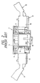
- Fig. 1 is an exploded perspective view of a conventional column and Fig. 2 is a section view of the column shown in Fig. 1 taken along the axial direction of a steering.
- An SRC 1 comprises an outer cylinder 3 which is a fixed member, and an inner cylinder 5 which is a rotating member and is coaxial with the outer cylinder 3. Between the outer cylinder 3 and inner cylinder 5, there is formed an annular storage chamber in which a cable 6 is stored in a spiral manner.
- the SRC 1 can be fixed to a column 9 in such a manner that a fixing portion 7 provided on the outer periphery of the outer cylinder 3 is fixed to a screw hole 11 formed in the column 9.
- the column 9 includes a pair of connector storage portions 13 which are respectively formed on the two side surfaces thereof; and, a lever unit, that is, a turn signal head lamp switch lever (a turn signal lever) 15 or a wiper control switch 17 is mounted into the corresponding one of connector storage portions 13. Also, a canceler 19 is assembled to the column 9.
- the canceler 19 includes an engaging projection 27 on the upper surface thereof and, in order to prevent its relative rotation to the SRC 1, the engaging projection 27 is engaged with the lower surface of the inner cylinder 5 of the SRC 1. Also, the canceler 19 can be rotated integrally with the steering and thus, if the canceler 19 is rotated integrally with steering, then it not only transmits the rotation of the steering to the inner cylinder 5 of the SRC 1 but also brings a canceler portion 23 into contact with a return portion (a cancel cam) 25 provided in a turn signal cancel mechanism (not shown) to thereby return or cancel the turn signal lever 15 to its neutral position. Between the canceler 19 and a base plate 29 provided in the column 9, there is interposed a spring 31 which is used to energize the canceler 19 toward the SRC 1.
- the canceler 19 is disposed on the lower surface of the column 9 in such a manner that it can be moved in the steering axial direction, and the spring 31 is used to energize the canceler 19 toward the SRC 1, there is required a wide space which extends in the steering axial direction and is used to store these component parts, which not only increases the size of the column structure but also increases the number of parts to be disposed in the steering axial direction to thereby increase the number of man-hour for assembling. Also, when the SRC 1 is stored within the column 9, because of the limited space, the cancel system must be replaced with an electronic system, which further increases the number of parts required as well as the cost of the whole device.
- EP-A-0 520 503 discloses a signal transmission device incorporated within a steering column.
- An outer cylinder is fixedly mounted on said column, while an inner cylinder is arranged to be rotated in unison with a steering shaft of said steering.
- a spirally arranged flat cable is contained in an annular chamber defined between said outer cylinder and said inner cylinder.
- One end of said cable is connected to male terminals and bus bars arranged on said inner cylinder, while the other end of said cable includes male terminals and bus bars for connecting with mating connectors of electrical devices.
- the present invention aims at eliminating the drawbacks found in the above-mentioned conventional signal transmission device for a steering. Accordingly, it is an object of the invention to provide a signal transmission device for a steering which can eliminate the need for provision of a movably structured canceler using a spring and can structure a compact column with the reduced number of parts and at a low cost.
- a signal transmission device for a steering comprising:
- the inner cylinder, the upper cover and the canceler portion are preferably formed integrally.
- the signal transmission device for a steering may also be structured such that an auxiliary device connecting connector is disposed in the upper cover and the other end of the cable is connected to the present auxiliary device connecting connector.
- the signal transmission device for a steering may also be structured such that a steering wheel mounting contact surface is formed in the other portion of the upper surface of the cover than the canceler portion, and either of the other end of the cable or the auxiliary device connecting connector is fixed to the upper surface of the canceler portion.
- the signal transmission device for a steering since there is employed the upper cover which can be rotated integrally with the steering and the canceler portion is integrally formed in the upper cover, not only the original function of a signal transmission device for a steering, that is, supply of electricity to the steering can be fulfilled but also the canceler portion can be contacted with the return portion of the turn signal cancel mechanism to thereby return the turn signal lever to its neutral position.
- the signal transmission device for a steering structured such that the auxiliary device connecting connector is disposed on the upper cover there can be eliminated the need for provision of a wiring harness, which makes it possible to connect the auxiliary device connecting connector directly to the auxiliary device terminal provided on the steering side.
- the steering wheel can be mounted onto the upper surface of the upper cover, so that the mounting height of the steering wheel can be lowered by an amount equivalent to the canceler portion.
- the signal transmission device for a steering structured such that the cable is stored in the annular storage chamber of the column, the signal transmission device for a steering can be assembled by using part of the column in common, which eliminates the need for provision of the outer cylinder.
- the column can be structured.
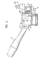
- Fig. 3 is a perspective view of a first embodiment of a signal transmission device for a steering according to the invention, which is shown together with a column; and, Fig. 4 is a partially sectional view of the signal transmission device for a steering shown in Fig. 3, illustrating a state thereof in which it is assembled to the column.
- a column 41 includes a pair of connector storage portions 42 respectively formed on the two side surfaces thereof, while each of the connector storage portions 42 is arranged such that it can store therein a connector portion 43a or 44a formed in the base end portion of a lever unit, that is, a turn signal head lamp switch lever (turn signal lever) 43 or a wiper control switch lever 44.
- the column 41 also includes an annular recessed portion 45 having an open upper surface in such a manner that the annular recessed portion 45 is coaxial with a steering shaft (not shown), while the annular recessed portion 45 is used to store and fix a signal transmission device for a steering (SRC) 46.
- the SRC 46 includes an outer cylinder (that is, an under cover) 47 and an inner cylinder (that is, a rotator) 49 which can be rotated inside the under cover 47. Between the under cover 47 and rotator 49, there is stored a cable 50 in a spiral manner. In the under cover 47, there is formed a guide portion 51 which is used to pull out one end 50a of a cable to the outside.
- the rotator 49 is mounted on the outer periphery of the steering shaft in such a manner that it is prevented from rotating with respect to the steering shaft.
- the rotator 49 includes a disk-shaped upper cover 53 which is formed integrally with the rotator 49 and can be rotated while covering the upper surface opening of the under cover 47.
- the upper cover 53 includes an upper surface 53a and a platform plate portion 55 which is formed integrally with and projected from the upper surface 53a.
- the upper surface of the platform plate portion 55 is used as a contact surface 55a for mounting a steering wheel.
- On the contact surface 55a of the platform plate portion 55 there are erected a pair of bosses 56 which are respectively used to position a steering wheel.
- the platform plate portion 55 includes a pressure surface (that is, a canceler portion) 57 which is formed by removing part of the circumferential portion of the platform plate portion 55 in such a manner that it is perpendicular to the upper surface 53a and stands up in the radial direction of the upper cover 53.
- canceler 57 If the canceler 57 is rotated integrally with the upper cover 53 with the return rotation of the steering, then it is butted against a return portion (that is, a cancel cam) 59 provided in a turn signal cancel mechanism to thereby return the turn signal lever 43 to its neutral position.
- a return portion that is, a cancel cam
- the column 41 includes a collective connector 61 formed integrally therewith; and, electric circuits respectively for the turn signal lever 43, wiper control switch lever 44, cable end 50a drawn out from the guide portion 51 of the under cover 47, a sensor and the like are collectively connected to the collective connector 61.
- the SRC 46 since there is used the upper cover 53 rotatable integrally with the steering and the canceler portion 57 is formed integrally with the upper cover 53, the SRC 46 not only can fulfil its original function, that is, can supply electricity to the steering, but also can come into contact with the return portion 59 of the turn signal cancel mechanism to thereby return the turn signal lever 43 to its neutral position.
- FIG. 5 is a perspective view of the second embodiment of a signal transmission device for a steering according to the invention.
- the same parts or portions as those shown in Figs. 3 and 4 are given the same designations and thus the duplicated description thereof is omitted here.
- An SRC 71 includes an auxiliary device connecting connector 73 on the upper surface of the platform plate portion 55 in place of the above-mentioned cable 50b which is guided from the upper surface of the upper cover 53.
- the auxiliary device connecting connector 73 is connected to the other end of a cable built in the SRC 71 and is arranged such that, when the steering wheel is mounted onto the steering shaft, it can be fitted directly with an auxiliary device terminal (not shown) such as a squib or the like which is provided on the steering.
- the auxiliary device connecting connector 73 is disposed on the upper cover 53 and is arranged such that it can be directly connected to the auxiliary device terminal on the steering side. Due to this, not only provision of a wiring harness can be eliminated but also the auxiliary device connecting connector 73 can be connected to the auxiliary device terminal at the same time when the steering is mounted, which can reduce the number of man-hour in operation.
- Fig. 6 is a perspective view of the third embodiment of a signal transmission device for a steering according to the invention
- Fig. 7 is a perspective view of a modification of the signal transmission device for a steering shown in Fig. 6.
- the platform plate portion 55 except for the above-mentioned canceler portion 57 is omitted.
- a pair of bosses are erected directly on the upper surface 53a of the upper cover 53.
- a take-out opening 83 (see Fig. 6) for taking out the other end 50b of the cable or an auxiliary device connecting connector 73 (see Fig. 7) is disposed on the upper surface 57a of the canceler portion 57.
- the upper surface 53a of the upper cover 53 is used as a contact surface with the steering wheel, and the present contact surface is lower in height, by an amount corresponding to the platform plate portion 55 omitted, when compared with the above-mentioned SRC 46.
- the canceler portion 57 is projected upwardly from the lower surface of the steering wheel through a notch or the like formed in the lower surface of the steering wheel (not shown) and, in its projecting state, the canceler portion 57 can be contacted with the return portion 59 of the turn signal cancel mechanism to thereby return the turn signal lever 43 to its neutral position.
- the height of the column 41 in the steering shaft direction can be reduced by an amount equivalent to the omitted portion of the platform plate portion 55, which makes it possible to reduce the size of the column 41 further.
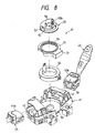
- Fig. 8 is an exploded perspective view of the fourth embodiment of a signal transmission device for a steering according to the invention, together with a column.
- Fig. 8 the same parts or portions as those shown in Figs. 3 and 4 are given the same designations and thus the duplicated description thereof is omitted here.
- an SRC 91 in the upper surface of a column 41, there is formed an annular recessed portion 93 coaxially with the steering shaft, while a cable 50 can be stored directly in the present annular recessed portion 93.
- the annular recessed portion 93 with the cable 50 stored therein is closed by a cover 97 including a steering shaft insertion hole 95.
- an upper cover 53 which can be rotated integrally with the steering shaft.
- the upper cover 53 is arranged such that the other end 50b of the cable 50 can be guided out from the upper surface thereof.
- the SRC 91 since the annular recessed portion 93 for storing the cable 50 therein is formed in the column 41, the SRC 91 can be assembled using part of the column 41 in common, which eliminates the provision of the under cover 47 (see Fig. 4). This not only can reduce the number of parts but also can reduce the size of the column 41 by an amount equivalent to the under cover 47 omitted.
- the canceler portion is formed integrally on the upper cover which can be rotated integrally with the steering, there can be omitted a conventional canceler of a movable structure using a spring, so that the column can be assembled to the present signal transmission device for a steering with the reduced number of parts, in a compact manner, and at an inexpensive cost.
- the signal transmission device for a steering structured such that the auxiliary device connecting connector is disposed on the upper cover there can be eliminated the provision of a wiring harness, which makes it possible to connect the auxiliary device connecting connector to the auxiliary device terminal at the same time when the steering is mounted, thereby being able to reduce the number of man-hour in operation.
- the steering wheel can be directly contacted with and mounted onto the upper surface of the upper cover, so that the mounting height of the steering wheel can be lowered by an amount equivalent to the canceler portion.
Landscapes
- Engineering & Computer Science (AREA)
- Mechanical Engineering (AREA)
- Steering Controls (AREA)
- Lighting Device Outwards From Vehicle And Optical Signal (AREA)
- Switches With Compound Operations (AREA)
Claims (5)
- Dispositif de transmission de signaux pour une direction, comprenant :caractérisé parune colonne (41);un cylindre extérieur (47) monté fixe sur ladite colonne (41);un cylindre intérieur (49) disposé de manière à pouvoir tourner à l'intérieur et concentriquement audit cylindre extérieur (47); etun câble (50) disposé en spirale, logé dans une chambre de logement annulaire définie entre ledit cylindre extérieur (47) et ledit cylindre intérieur (49), une extrémité (50a) dudit câble (50) étant supportée dans ledit cylindre extérieur (47), l'autre extrémité (50b) dudit câble (50) étant supportée dans ledit cylindre intérieur (49);
un levier de signalisation de braquage (43) monté sur ladite colonne (41) et déplaçable dans une zone incluant sa position neutre, ledit levier de signalisation de braquage (43) possédant un mécanisme d'annulation du signal de braquage comportant une partie de rappel (59);
dans lequel ledit cylindre intérieur (49) est pourvu d'un capot supérieur (53) possédant une partie formant dispositif de rappel (57), qui peut être amenée en contact avec ladite partie de retour (59) de manière à ramener ledit levier de signalisation de braquage (43) dans sa position neutre. - Dispositif de transmission de signaux pour une direction selon la revendication 1, dans lequel ledit cylindre intérieur (49), ledit capot supérieur et ladite partie formant dispositif de rappel (57) sont formés d'un seul tenant.
- Dispositif de transmission de signaux pour une direction selon la revendication 1, dans lequel un connecteur (73) de connexion d'un dispositif auxiliaire est formé dans ledit capot supérieur (53), et ladite autre extrémité (40b) dudit câble (50) est connectée audit connecteur (73) de connexion du dispositif auxiliaire.
- Dispositif de transmission de signaux pour une direction selon la revendication 1, dans lequel la surface de contact (53a) de montage du volant de direction est formée dans la partie de la surface supérieure dudit capot (53) autre que ladite partie formant dispositif de rappel (57), et ladite autre extrémité (50b) dudit câble est prévue sur la surface supérieure (57a) de ladite partie formant dispositif de rappel (57).
- Dispositif de transmission de signaux pour une direction selon la revendication 3, dans lequel une surface de contact (53a) pour le montage du volant de direction est formée dans la partie de la surface supérieure dudit capot (53), autre que ladite partie formant dispositif de rappel (57), et de ladite autre extrémité du câble et dudit connecteur (73) de connexion du dispositif auxiliaire est fixé à la surface supérieure (57a) de la partie formant dispositif de rappel (57).
Applications Claiming Priority (3)
| Application Number | Priority Date | Filing Date | Title |
|---|---|---|---|
| JP3933897A JPH10241504A (ja) | 1997-02-24 | 1997-02-24 | ステアリング用信号伝達装置 |
| JP3933897 | 1997-02-24 | ||
| JP39338/97 | 1997-02-24 |
Publications (3)
| Publication Number | Publication Date |
|---|---|
| EP0860330A2 EP0860330A2 (fr) | 1998-08-26 |
| EP0860330A3 EP0860330A3 (fr) | 2000-01-26 |
| EP0860330B1 true EP0860330B1 (fr) | 2003-08-27 |
Family
ID=12550312
Family Applications (1)
| Application Number | Title | Priority Date | Filing Date |
|---|---|---|---|
| EP98103223A Expired - Lifetime EP0860330B1 (fr) | 1997-02-24 | 1998-02-24 | Dispositif de transmission de signaux pour une colonne de direction |
Country Status (4)
| Country | Link |
|---|---|
| US (1) | US5936215A (fr) |
| EP (1) | EP0860330B1 (fr) |
| JP (1) | JPH10241504A (fr) |
| DE (1) | DE69817418T2 (fr) |
Families Citing this family (34)
| Publication number | Priority date | Publication date | Assignee | Title |
|---|---|---|---|---|
| EP0968102B1 (fr) * | 1997-03-20 | 2004-02-18 | Delphi Technologies, Inc. | Ensemble colonne de direction |
| AU734495B2 (en) * | 1997-05-20 | 2001-06-14 | Matsushita Electric Industrial Co., Ltd. | Automotive combination switch |
| US6236004B1 (en) * | 1998-03-20 | 2001-05-22 | Delco Electronics Europe Gmbh | Steering column assembly |
| JP3518662B2 (ja) * | 1998-05-08 | 2004-04-12 | アルプス電気株式会社 | 回転コネクタ |
| JP2000003638A (ja) * | 1998-06-15 | 2000-01-07 | Sumitomo Wiring Syst Ltd | ケーブルリールとコンビネーションスイッチとの取付構造 |
| JP3503875B2 (ja) * | 1998-11-25 | 2004-03-08 | 矢崎総業株式会社 | コンビネーションスイッチ装置 |
| DE19926278C1 (de) | 1999-06-09 | 2001-02-15 | Kostal Leopold Gmbh & Co Kg | Vorrichtung zum Übertragen von Energie |
| JP2001206143A (ja) | 2000-01-24 | 2001-07-31 | Yazaki Corp | ステアリング用信号伝達装置 |
| US6384351B1 (en) * | 2000-03-23 | 2002-05-07 | Valeo Electrical Systems, Inc. | Switch apparatus for actuating a plurality of electrical circuits |
| JP2001294104A (ja) | 2000-04-11 | 2001-10-23 | Sumitomo Wiring Syst Ltd | ケーブルリールとコンビスイッチとの一体型電装品 |
| JP2001294161A (ja) * | 2000-04-14 | 2001-10-23 | Sumitomo Wiring Syst Ltd | ケーブルリールとコンビスイッチの組立体 |
| JP3718616B2 (ja) | 2000-05-12 | 2005-11-24 | アルプス電気株式会社 | ステアリング装置への回転コネクタの取り付け構造 |
| JP3681623B2 (ja) * | 2000-08-25 | 2005-08-10 | アルプス電気株式会社 | 回転コネクタ |
| JP4629854B2 (ja) * | 2000-11-14 | 2011-02-09 | ナイルス株式会社 | 車両用コンビネーションスイッチ |
| JP2002154440A (ja) | 2000-11-17 | 2002-05-28 | Yazaki Corp | ステアリング用舵角センサの取付構造 |
| JP3944376B2 (ja) * | 2001-10-17 | 2007-07-11 | ナイルス株式会社 | 車両用レバースイッチ |
| JP2003263938A (ja) * | 2002-03-07 | 2003-09-19 | Matsushita Electric Ind Co Ltd | レバースイッチ及びこれを用いた複合スイッチ |
| DE10236142A1 (de) * | 2002-08-07 | 2004-02-19 | Valeo Schalter Und Sensoren Gmbh | Lenkstockmodul und Montageverfahren |
| US6876300B2 (en) | 2002-11-25 | 2005-04-05 | Richard L. Ponziani | Electronic intelligent turn signal control system |
| EP1594723B1 (fr) * | 2003-02-20 | 2006-12-27 | Yazaki Corporation | Module de commutateur multiple |
| US20050073195A1 (en) * | 2003-10-06 | 2005-04-07 | Popilek Mark E. | Steering wheel mounted scroll wheel and method |
| JP2007008341A (ja) * | 2005-06-30 | 2007-01-18 | Alps Electric Co Ltd | 車載用コンビネーションスイッチ |
| US7518071B2 (en) * | 2007-07-26 | 2009-04-14 | Grote Industries, Inc. | Turn signal self cancellation system |
| US8424409B2 (en) * | 2008-07-01 | 2013-04-23 | Ghsp, Inc. | Shifter with one-touch assembly |
| DE102009037672B4 (de) * | 2009-08-14 | 2014-01-16 | TAKATA Aktiengesellschaft | Lenkvorrichtung für ein Kraftfahrzeug mit einem Lenkrad und einer elektronischen Kontakteinheit |
| JP5752395B2 (ja) * | 2010-11-09 | 2015-07-22 | 矢崎総業株式会社 | 操作ユニット |
| FR2984818B1 (fr) * | 2011-12-23 | 2015-12-11 | Sc2N Sa | Module de communication de colonne de direction |
| FR3007707B1 (fr) * | 2013-06-27 | 2015-07-17 | Sc2N Sa | Contacteur tournant pour une colonne de direction de vehicule automobile |
| CN103456546B (zh) * | 2013-07-30 | 2016-01-13 | 黄山奥特斯电气股份有限公司 | 一种汽车组合开关 |
| DE102013016507A1 (de) * | 2013-10-02 | 2015-04-02 | Valeo Schalter Und Sensoren Gmbh | Verbindungsvorrichtung für ein Lenkrad eines Kraftfahrzeugs, Kraftfahrzeug und Verfahren zum Montieren eines Lenkrads an einer Lenksäule |
| CN106427770A (zh) * | 2016-11-01 | 2017-02-22 | 南京依维柯汽车有限公司 | 一种集成螺旋电缆的自动回位探针机构及其工作方法 |
| US11034374B2 (en) | 2017-08-10 | 2021-06-15 | Toyoda Gosei Co., Ltd. | Steering wheel |
| JP6933067B2 (ja) * | 2017-09-15 | 2021-09-08 | 豊田合成株式会社 | ステアリングホイール |
| US11970179B2 (en) | 2021-09-29 | 2024-04-30 | Zero Motorcycles, Inc. | Turn signal cancelation systems and methods for two-wheeled vehicles |
Family Cites Families (16)
| Publication number | Priority date | Publication date | Assignee | Title |
|---|---|---|---|---|
| DE2810790C3 (de) * | 1978-03-13 | 1980-10-09 | Adam Opel Ag, 6090 Ruesselsheim | Lenkstockschalter für Kraftfahrzeuge |
| JPS58150230A (ja) * | 1982-03-03 | 1983-09-06 | ナイルス部品株式会社 | 車両用コラムスイツチの取付装置 |
| US4859816A (en) * | 1988-02-22 | 1989-08-22 | Metro Denso Kabushiki Kaisha | Self canceller for a turn signal indicator |
| JPH0321544A (ja) * | 1989-06-15 | 1991-01-30 | Daihatsu Motor Co Ltd | 配線装置 |
| JPH0711424Y2 (ja) * | 1990-10-05 | 1995-03-15 | 古河電気工業株式会社 | 回転コネクタ |
| JP3050636B2 (ja) * | 1991-06-04 | 2000-06-12 | 古河電気工業株式会社 | コネクタ装置 |
| JP2576602Y2 (ja) * | 1991-06-28 | 1998-07-16 | 古河電気工業株式会社 | 自動車用ブラシレス電気信号装置 |
| JP2538866Y2 (ja) * | 1991-11-15 | 1997-06-18 | 古河電気工業株式会社 | 回転コネクタ |
| DE4422305C2 (de) * | 1994-06-17 | 1996-06-20 | Kostal Leopold Gmbh & Co Kg | Elektrische Einrichtung |
| DE4428883C1 (de) * | 1994-08-17 | 1995-12-14 | Kostal Leopold Gmbh & Co Kg | Einrichtung für Kraftfahrzeuge |
| GB2301232B (en) * | 1995-05-23 | 1998-11-18 | Niles Parts Co Ltd | Rotary connector device |
| US5977494A (en) * | 1995-09-08 | 1999-11-02 | Yazaki Corporation | Symmetrically mounted switches on steering wheel column body including wiring connection and control unit |
| JP3637120B2 (ja) * | 1995-11-01 | 2005-04-13 | ナイルス株式会社 | 回転コネクタを備えたコンビネーションスイッチ装置 |
| JP3117632B2 (ja) * | 1995-11-24 | 2000-12-18 | ナイルス部品株式会社 | 回転コネクタとスイッチとの取付構造 |
| EP0823352B1 (fr) * | 1996-08-05 | 2001-03-14 | Alps Electric Co., Ltd. | Fixation pour connecteur rotatif et connecteur rotatif |
| US5773776A (en) * | 1996-10-21 | 1998-06-30 | Ut Automotive Dearborn, Inc. | Steering wheel assembly |
-
1997
- 1997-02-24 JP JP3933897A patent/JPH10241504A/ja not_active Abandoned
-
1998
- 1998-02-24 EP EP98103223A patent/EP0860330B1/fr not_active Expired - Lifetime
- 1998-02-24 US US09/028,309 patent/US5936215A/en not_active Expired - Lifetime
- 1998-02-24 DE DE69817418T patent/DE69817418T2/de not_active Expired - Lifetime
Also Published As
| Publication number | Publication date |
|---|---|
| EP0860330A2 (fr) | 1998-08-26 |
| DE69817418T2 (de) | 2004-03-11 |
| DE69817418D1 (de) | 2003-10-02 |
| JPH10241504A (ja) | 1998-09-11 |
| US5936215A (en) | 1999-08-10 |
| EP0860330A3 (fr) | 2000-01-26 |
Similar Documents
| Publication | Publication Date | Title |
|---|---|---|
| EP0860330B1 (fr) | Dispositif de transmission de signaux pour une colonne de direction | |
| EP0763447B1 (fr) | Ensemble de commutateurs | |
| US6008457A (en) | Assembly for steering column switch with spiral spring | |
| US6364676B2 (en) | Device for transmitting energy | |
| US4840078A (en) | Steering device for vehicles | |
| GB2073961A (en) | Electrical connector | |
| US5951311A (en) | Rotary connector | |
| JP2006502549A (ja) | 大電流容量を有するループバッククロックスプリングコネクタ | |
| EP0823352B1 (fr) | Fixation pour connecteur rotatif et connecteur rotatif | |
| GB2282014A (en) | Cable connector | |
| US5993228A (en) | Circuit connecting device of steering module for vehicle | |
| JP2000021273A (ja) | コラムスイッチ | |
| JP3503875B2 (ja) | コンビネーションスイッチ装置 | |
| EP0926009B1 (fr) | Interrupteur de colonne de direction avec connecteur rotatif | |
| JP3134023B2 (ja) | コネクタ部付きスイッチ | |
| EP1120318B1 (fr) | Dispositif de transmission de signaux pour une direction | |
| EP0880205B1 (fr) | Structure de montage pour connecteur rotatif | |
| US5721408A (en) | Electrical connector used with steering wheel of automobile | |
| US6172313B1 (en) | Acceleration detecting device | |
| JP3301929B2 (ja) | ハンドルユニット | |
| US20060146860A1 (en) | Combination switch module | |
| JP3424904B2 (ja) | ステアリング装置 | |
| JPH0735225A (ja) | ポジション信号発生スイッチ | |
| JPH1074573A (ja) | 回転コネクタ | |
| JPH0743977B2 (ja) | トリガースイッチ |
Legal Events
| Date | Code | Title | Description |
|---|---|---|---|
| PUAI | Public reference made under article 153(3) epc to a published international application that has entered the european phase |
Free format text: ORIGINAL CODE: 0009012 |
|
| AK | Designated contracting states |
Kind code of ref document: A2 Designated state(s): DE FR GB |
|
| AX | Request for extension of the european patent |
Free format text: AL;LT;LV;MK;RO;SI |
|
| PUAL | Search report despatched |
Free format text: ORIGINAL CODE: 0009013 |
|
| AK | Designated contracting states |
Kind code of ref document: A3 Designated state(s): AT BE CH DE DK ES FI FR GB GR IE IT LI LU MC NL PT SE |
|
| AX | Request for extension of the european patent |
Free format text: AL;LT;LV;MK;RO;SI |
|
| 17P | Request for examination filed |
Effective date: 20000707 |
|
| AKX | Designation fees paid |
Free format text: DE FR GB |
|
| 17Q | First examination report despatched |
Effective date: 20020502 |
|
| GRAH | Despatch of communication of intention to grant a patent |
Free format text: ORIGINAL CODE: EPIDOS IGRA |
|
| GRAS | Grant fee paid |
Free format text: ORIGINAL CODE: EPIDOSNIGR3 |
|
| GRAA | (expected) grant |
Free format text: ORIGINAL CODE: 0009210 |
|
| AK | Designated contracting states |
Designated state(s): DE FR GB |
|
| REG | Reference to a national code |
Ref country code: GB Ref legal event code: FG4D |
|
| REF | Corresponds to: |
Ref document number: 69817418 Country of ref document: DE Date of ref document: 20031002 Kind code of ref document: P |
|
| ET | Fr: translation filed | ||
| PLBE | No opposition filed within time limit |
Free format text: ORIGINAL CODE: 0009261 |
|
| STAA | Information on the status of an ep patent application or granted ep patent |
Free format text: STATUS: NO OPPOSITION FILED WITHIN TIME LIMIT |
|
| 26N | No opposition filed |
Effective date: 20040528 |
|
| REG | Reference to a national code |
Ref country code: FR Ref legal event code: PLFP Year of fee payment: 19 |
|
| REG | Reference to a national code |
Ref country code: FR Ref legal event code: PLFP Year of fee payment: 20 |
|
| PGFP | Annual fee paid to national office [announced via postgrant information from national office to epo] |
Ref country code: DE Payment date: 20170221 Year of fee payment: 20 Ref country code: FR Payment date: 20170112 Year of fee payment: 20 |
|
| PGFP | Annual fee paid to national office [announced via postgrant information from national office to epo] |
Ref country code: GB Payment date: 20170222 Year of fee payment: 20 |
|
| REG | Reference to a national code |
Ref country code: DE Ref legal event code: R071 Ref document number: 69817418 Country of ref document: DE |
|
| REG | Reference to a national code |
Ref country code: GB Ref legal event code: PE20 Expiry date: 20180223 |
|
| PG25 | Lapsed in a contracting state [announced via postgrant information from national office to epo] |
Ref country code: GB Free format text: LAPSE BECAUSE OF EXPIRATION OF PROTECTION Effective date: 20180223 |