EP0863086A2 - System und Verfahren zum mechanischen verschliessen von Behälteröffungen - Google Patents
System und Verfahren zum mechanischen verschliessen von Behälteröffungen Download PDFInfo
- Publication number
- EP0863086A2 EP0863086A2 EP98301238A EP98301238A EP0863086A2 EP 0863086 A2 EP0863086 A2 EP 0863086A2 EP 98301238 A EP98301238 A EP 98301238A EP 98301238 A EP98301238 A EP 98301238A EP 0863086 A2 EP0863086 A2 EP 0863086A2
- Authority
- EP
- European Patent Office
- Prior art keywords
- container
- mechanical plug
- neck region
- mechanical
- plug
- Prior art date
- Legal status (The legal status is an assumption and is not a legal conclusion. Google has not performed a legal analysis and makes no representation as to the accuracy of the status listed.)
- Withdrawn
Links
Images


Classifications
-
- B—PERFORMING OPERATIONS; TRANSPORTING
- B65—CONVEYING; PACKING; STORING; HANDLING THIN OR FILAMENTARY MATERIAL
- B65D—CONTAINERS FOR STORAGE OR TRANSPORT OF ARTICLES OR MATERIALS, e.g. BAGS, BARRELS, BOTTLES, BOXES, CANS, CARTONS, CRATES, DRUMS, JARS, TANKS, HOPPERS, FORWARDING CONTAINERS; ACCESSORIES, CLOSURES, OR FITTINGS THEREFOR; PACKAGING ELEMENTS; PACKAGES
- B65D41/00—Caps, e.g. crown caps or crown seals, i.e. members having parts arranged for engagement with the external periphery of a neck or wall defining a pouring opening or discharge aperture; Protective cap-like covers for closure members, e.g. decorative covers of metal foil or paper
- B65D41/02—Caps or cap-like covers without lines of weakness, tearing strips, tags, or like opening or removal devices
- B65D41/16—Snap-on caps or cap-like covers
- B65D41/18—Snap-on caps or cap-like covers non-metallic, e.g. made of paper or plastics
-
- B—PERFORMING OPERATIONS; TRANSPORTING
- B65—CONVEYING; PACKING; STORING; HANDLING THIN OR FILAMENTARY MATERIAL
- B65D—CONTAINERS FOR STORAGE OR TRANSPORT OF ARTICLES OR MATERIALS, e.g. BAGS, BARRELS, BOTTLES, BOXES, CANS, CARTONS, CRATES, DRUMS, JARS, TANKS, HOPPERS, FORWARDING CONTAINERS; ACCESSORIES, CLOSURES, OR FITTINGS THEREFOR; PACKAGING ELEMENTS; PACKAGES
- B65D51/00—Closures not otherwise provided for
- B65D51/18—Arrangements of closures with protective outer cap-like covers or of two or more co-operating closures
-
- B—PERFORMING OPERATIONS; TRANSPORTING
- B65—CONVEYING; PACKING; STORING; HANDLING THIN OR FILAMENTARY MATERIAL
- B65D—CONTAINERS FOR STORAGE OR TRANSPORT OF ARTICLES OR MATERIALS, e.g. BAGS, BARRELS, BOTTLES, BOXES, CANS, CARTONS, CRATES, DRUMS, JARS, TANKS, HOPPERS, FORWARDING CONTAINERS; ACCESSORIES, CLOSURES, OR FITTINGS THEREFOR; PACKAGING ELEMENTS; PACKAGES
- B65D41/00—Caps, e.g. crown caps or crown seals, i.e. members having parts arranged for engagement with the external periphery of a neck or wall defining a pouring opening or discharge aperture; Protective cap-like covers for closure members, e.g. decorative covers of metal foil or paper
- B65D41/02—Caps or cap-like covers without lines of weakness, tearing strips, tags, or like opening or removal devices
- B65D41/023—Caps or cap-like covers without lines of weakness, tearing strips, tags, or like opening or removal devices with integral internal sealing means
-
- B—PERFORMING OPERATIONS; TRANSPORTING
- B65—CONVEYING; PACKING; STORING; HANDLING THIN OR FILAMENTARY MATERIAL
- B65D—CONTAINERS FOR STORAGE OR TRANSPORT OF ARTICLES OR MATERIALS, e.g. BAGS, BARRELS, BOTTLES, BOXES, CANS, CARTONS, CRATES, DRUMS, JARS, TANKS, HOPPERS, FORWARDING CONTAINERS; ACCESSORIES, CLOSURES, OR FITTINGS THEREFOR; PACKAGING ELEMENTS; PACKAGES
- B65D53/00—Sealing or packing elements; Sealings formed by liquid or plastics material
- B65D53/02—Collars or rings
Definitions
- This invention relates generally to a system and a method for mechanically closing an opening of a pouch or a container, and relates more particularly to a system and a method for closing an opening of a pouch or a container by using a combination of a plug mechanism and an annular ring mechanism.
- the task of filling a pouch or a container with a liquid content and ensuring that the content is tightly sealed may be achieved by one of two approaches: fill a pouch or a container which has an opening for introducing the liquid content and subsequently seal the opening; or fill a sealed pouch or container using a liquid-introducing needle and subsequently seal the puncture point.
- Both methods generally require application of external sealing agents, the efficacy of which sealing agents may be subject to the material characteristics of the container, for the purpose of forming tight seals. Material characteristics of the container are usually constant, but should they vary, these characteristics would affect the tightness of the seal.
- the present invention provides a mechanical lid or a plug which interacts with an opening of a pouch or a container, as well as with a rigid ring placed inside the container opening.
- the mechanical plug is snapped into the container opening such that the mechanical plug compresses both the outside of the opening and the inner face of the ring placed inside the container opening, thereby forming a tight seal of the opening.
- the opening area of the container has an annular recess configured to accommodate the rigid ring, where the rigid ring is snapped into the annular recess.
- the mechanical plug is snapped both into the rigid ring and around the outside edge of the container opening so that the container opening is compressed between the rigid ring and the mechanical plug.
- the radial edge of the inner face of the mechanical plug is formed as a an arch-shaped region which extends around the plug such that the radial edge of the plug is adapted to "hug" the perimeter of the container opening.
- attached to the inner face of the mechanical plug are two or more legs which extend perpendicular to the lower surface of the mechanical plug.
- the ends of the legs are hook-shaped to engage the bottom of the rigid ring/radial groove combination.
- the annular recess and the legs of the mechanical plug facilitate both vertical and radial compression of the opening region of the container and the rigid ring. In this manner, a tight seal of the container opening is ensured.
- the outside surface of the opening region of the container and the interior surface of the annular recess of the mechanical plug each has one or more protrusions, or "interferences.”
- the resulting compression of the container material tends to cause displacement, or "creep,” of the compressed material towards areas of lesser compression.
- the protrusions limit the range of displacement of the compressed container material, i.e., force the container material displaced by compression to remain within a defined area, thereby ensuring the tightness of the seal for a prolonged period of time.
- the central inner surface of the mechanical plug may be equipped with an extension or a plunger which is adapted to extend into the liquid content of the container in such a way that the mechanical plug snaps tightly into the container opening after, and only after, the plunger has displaced the surface level of the liquid up to the upper edge of the container opening, thereby obviating the need for a vacuum condition normally utilized for an air-less filling process.
- the plunger substantially reduces the residual air bubbles which may otherwise remain between the surface of the liquid and the inner surface of the mechanical plug.
- the mechanical closure system and method according to the present invention may be used for any application in which an opening of a pouch or a container needs to be tightly sealed.
- the mechanical closure system according to the present invention is particularly well suited for closing medicament containers or pouches containing medicament. Because the mechanical closure system according to the present invention achieves a substantially hermetic seal without the need for caulking materials, glues or other external sealing agents, expensive sealing systems for applying the external sealing agents are not necessary.
- the allowable mechanical tolerances of the interacting components of the mechanical closure system are increased.
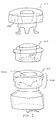
- Fig. 1 is an exploded view of components of one preferred embodiment of the mechanical closure system according to the present invention.
- Fig. 2 is an exploded cross-sectional view of components of the preferred embodiment of the mechanical closure system according to the present invention shown in Fig. 1.
- Fig. 3 is a cross-sectional view of assembled components of the preferred embodiment of the mechanical closure system according to the present invention shown in Fig. 1.
- Fig. 4 is an exploded cross-sectional view of components of another preferred embodiment of the mechanical closure system according to the present invention.
- Fig. 5 is a cross-sectional view of assembled components of the preferred embodiment of the mechanical closure system according to the present invention shown in Fig. 4.
- the first embodiment of the present invention includes a mechanical lid or plug 101 and a rigid annular ring 102, both of which interact with a neck region 103d near an opening 103b of a pouch or container 103 to tightly seal the opening 103b.
- the pouch or container 103 may be made of any one of several materials well known in the art, including butadiene polyethylene styrene (KRATONTM), polyethylene, polyurethane or other plastic materials, thermoplastic elastomers or other elastic materials.
- the container 103 may be a medicament dispensing cartridge with a nozzle 103a.
- the contour of the rigid ring 102 is complementary to the inside contour 103c of the neck region 103d of the container 103 near the opening 103b, thereby allowing the rigid ring 102 to be snapped into the inside contour 103c of the neck region 103d.
- radial edge 101a of the mechanical plug 101 is formed as a U-shaped region which extends around the plug and complements the exterior contour of the combination of the rigid ring 102 and the neck region 103d.
- the mechanical plug 101 is subsequently snapped into place around the container opening 103b such that the U-shaped region 101a tightly engages the neck region 103d of the pouch 103 and the interior surface of the rigid ring 102.
- the U-shaped region 101a of the mechanical plug 101 has protrusions 1013, 1014 and 1015, and at least one recess 1016.
- the exterior surface of the neck region 103d of the mechanical plug has protrusions 1031 and 1033, and the interior surface of the neck region has a protrusion 1035.
- the rigid ring 102 has recesses 1021 and 1022 at the vertical interior surface 102a and the bottom surface, respectively. The recess 1022 of the rigid ring 102 accommodates the protrusion 1035 of the neck region 103d, thereby securely engaging the rigid ring to the neck region of the container 103 once the rigid ring has been snapped into place.
- the protrusions 1013, 1014 and 1015, as well as a portion 1018, of the U-shaped region 101a of the mechanical plug engage the recess 1021 of the rigid ring and portions 1034, 1036 and 1037 of the exterior surface of the neck region 103d, respectively.
- the protrusions 1031 and 1033 of the exterior surface of the neck region 103d engage a portion 1017 and the recess 1016 of the U-shaped region 101a of the mechanical plug.
- each of the legs 1011 has a hook-shaped end portion 1012 adapted to engage a recess region 1032 at the bottom interior of the assembled combination of the rigid ring 102 and the neck region 103d of the mechanical plug.
- the legs 1011 are flexible enough such that, during assembly of the mechanical closure system according to the present invention, the legs 1011 slide down the vertical interior surface 102a of the rigid ring and snap into place at the recess region 1032, against a portion 1038 of the neck region 103d of the container.
- the combination of the U-shaped region 101a and the legs 1011 of the mechanical plug 101 facilitates both vertical and radial compression of the neck region 103d of the container and the rigid ring against the mechanical plug.
- the portion 1012 of the legs 1011 interact with the portion 1023 of the rigid ring and the portion 1038 of the neck region 103d of the container
- portions 1014 and 1018 of the mechanical plug interact with portions 1034 and 1037 of the neck region 103d of the container, respectively, to vertically compress the neck region between the mechanical plug 101 and the rigid ring 102.
- the portions 1013, 1015 and 1017 of the U-shaped region 101a of the mechanical plug 101 interact with the portions 1021, 1036 and 1031, respectively, to radially compress the neck region 103d between the mechanical plug and the rigid ring 102. In this manner, a substantially hermetic seal of the container opening 103b is achieved, as shown in Fig. 3.
- the first embodiment of the mechanical closure system achieves two types of mechanical seals.
- a seal extending along the horizontal direction of the neck region e.g., the area extending between the portions 1034 and 1037, as well as the interface of the regions 1022 and 1035, is achieved by the vertical compression of the neck region 103d by the mechanical plug against the rigid ring 102.
- a seal extending along the vertical direction e.g., the area extending between the portions 1036 and 1034, as well as the interface of the regions 1021 and 1013, is achieved by the horizontal compression of the neck region 103d by the mechanical plug against the rigid ring 102.
- the resulting compression of the container material tends to cause displacement, or "creep,” of the compressed material towards areas of lesser compression.
- the protrusions force the container material displaced by compression to be confined within a restricted area, thereby ensuring the tightness of the seal for a prolonged period of time.
- the protrusions 1014 and 1015 of the mechanical plug 101 delimits the protrusion 1031 on the exterior surface of the neck region 103d of the container. Accordingly, when the material of the protrusion 1031 is initially compressed by the portions 1015 and 1017, the displaced material of the protrusion 1031 is forced towards the protrusion 1014, which limits any further movement of the displaced material, thereby maintaining a tight seal.
- the central portion of a lower surface 1019 of the mechanical plug 101 is preferably equipped with an extension or a plunger 1017 which is adapted to extend into the liquid content of the container before the mechanical plug 101 has been snapped into place around the container opening 103b.
- the inserted plunger 1017 forces the liquid level to rise, hence allowing air or gas bubbles to rise along with the liquid level and escape through the container opening 103b which is not yet sealed by the mechanical plug 101.
- the plunger 1017 substantially reduces the residual air bubbles which may otherwise remain between the surface of the liquid and the lower surface of the mechanical plug.
- the configuration and dimensions of the mechanical plug 101, the neck region 103d and the rigid ring 102 are such that the U-shaped region 101a and the legs 1011 of the mechanical plug interact with the neck region 103d and the rigid ring 102 to form a tight seal only after the plunger 1017 has forced the liquid level to rise to approximately the upper edge of the neck region 103d, thereby obviating the need for a vacuum condition normally utilized for an air-less filling process.
- the lower surface 1019 of the mechanical plug 101 is sloped in order to ensure that the air or gas bubbles which have been forced up to the surface level of the liquid by the insertion of the plunger 1017 are not trapped between the liquid level and the lower surface of the mechanical plug.
- the sloped surface 1019 facilitates radially upward movement of the air bubbles which eventually escape through the opening 103b of the container, via the area between the two legs 1011.
- the second embodiment of the present invention is substantially similar to the first embodiment and includes a mechanical plug or plug 401 and a rigid annular ring 402, both of which interact with a neck region 403d of a pouch or container 403.
- the contour of the rigid ring 402 is complementary to the inside contour of the neck region 403d of the container 403, thereby allowing the rigid ring 402 to be snapped into the inside contour of the neck region 403d.
- radial edge 401a of the mechanical plug 401 is formed as an arch-shaped region which extends around the plug and complements the exterior contour of the combination of the rigid ring 402 and the neck region 403d.
- the mechanical plug 401 is subsequently snapped into place around the container opening 403b defined by the neck region 403d such that the arch-shaped region 401a tightly engages the neck region 403d of the pouch 403 and the rigid ring 402, as shown in Fig. 5.
- the lower surface 4019 of the mechanical plug 401 of the second embodiment is sloped, or tapered, in order to ensure that the air or gas bubbles which have been forced up to the surface level of the liquid by the insertion of the plunger 4017 are directed radially upward and eventually escape through the opening 403b of the container, via the area between the two legs 4011.
- the second embodiment shown in Figs. 4 and 5 preferably have at least two legs 4011 attached to the lower surface of the mechanical plug 401, each of the legs having a hook-shaped region 4012 at the end.
- the hook-shaped region 4012 is adapted to engage a region 4023 at the bottom surface of the rigid annular ring 402.
- an extension or a plunger 4017 attached to the central lower surface of the mechanical plug 401 is an extension or a plunger 4017 which is adapted to extend into the liquid content of the container before the mechanical plug 401 is snapped into place around the container opening 403b, thereby substantially reducing the residual air bubbles which may otherwise remain between the surface of the liquid and the lower surface of the mechanical plug.
- the second embodiment of the mechanical closure system according to the present invention utilizes fewer protrusions on the surfaces of the mechanical plug 401 and the neck region 403d than the number of protrusions found on the corresponding parts of the first embodiment.
- the unique arrangement of the interacting components i.e., the mechanical plug 401, the rigid ring 402 and the neck region 403d, ensures a substantially hermetic seal of the pouch 403. As shown in Figs.
- a protrusion 4015 and a region 4017 of the mechanical plug interact with a region 4031 of the neck region 403d, which region 4031 includes a protrusion from the regular contour of the exterior surface of the neck region 403d, and a portion 4016 of the mechanical plug interacts with the region 4022 of the rigid ring 402, thereby achieving radial compression of the rigid ring 402 and the neck region 403d.
- portions 4016 and 4012 of the mechanical plug interact with regions 4022 and 4023 of the rigid ring 402 to vertically compress the neck region 403d and the rigid ring 402.
- the second embodiment of the mechanical closure system provides the protrusion 4015 at the radial edge of the mechanical plug 401.
- the protrusion 4015 forces the container material of region 4031 displaced by compression to be channeled upwards, towards a space 4018 delimited by the annular rigid ring 402. Accordingly, the protrusion 4015 and the rigid ring 402 confine the displaced material of the region 4031 of the container 403, thereby maintaining a tight seal for a prolonged period of time.
Landscapes
- Engineering & Computer Science (AREA)
- Mechanical Engineering (AREA)
- Closures For Containers (AREA)
- Packages (AREA)
Applications Claiming Priority (2)
| Application Number | Priority Date | Filing Date | Title |
|---|---|---|---|
| US80871697A | 1997-02-28 | 1997-02-28 | |
| US808716 | 1997-02-28 |
Publications (2)
| Publication Number | Publication Date |
|---|---|
| EP0863086A2 true EP0863086A2 (de) | 1998-09-09 |
| EP0863086A3 EP0863086A3 (de) | 1999-04-14 |
Family
ID=25199521
Family Applications (1)
| Application Number | Title | Priority Date | Filing Date |
|---|---|---|---|
| EP98301238A Withdrawn EP0863086A3 (de) | 1997-02-28 | 1998-02-19 | System und Verfahren zum mechanischen verschliessen von Behälteröffungen |
Country Status (5)
| Country | Link |
|---|---|
| EP (1) | EP0863086A3 (de) |
| JP (1) | JPH10273155A (de) |
| KR (1) | KR19980071816A (de) |
| AU (1) | AU5639398A (de) |
| CA (1) | CA2229944A1 (de) |
Cited By (1)
| Publication number | Priority date | Publication date | Assignee | Title |
|---|---|---|---|---|
| EP1237607A4 (de) * | 1999-12-14 | 2006-12-20 | Py Daniel C | System und vorrichtung zum verabreichen von medikamenten in die nasenpassage |
Family Cites Families (4)
| Publication number | Priority date | Publication date | Assignee | Title |
|---|---|---|---|---|
| DE603165C (de) * | 1934-09-24 | Adolf Schwieger | Dichtungsring zwischen den Raendern des Deckels und des Unterteiles von Dosen und Behaeltern, insbesondere fuer Schuhputzmittel, Bohnermasse u. dgl. | |
| FR1089047A (fr) * | 1953-12-04 | 1955-03-14 | Franco Suisse D Emboutissage | Bouchon pour réservoir de liquide |
| CH424512A (de) * | 1965-08-20 | 1966-11-15 | Buehler Josef | Verschluss für Behälter, insbesondere Flaschen |
| GB9120964D0 (en) * | 1991-10-03 | 1991-11-13 | Unilever Plc | Attachment for a container |
-
1998
- 1998-02-19 EP EP98301238A patent/EP0863086A3/de not_active Withdrawn
- 1998-02-19 CA CA002229944A patent/CA2229944A1/en not_active Abandoned
- 1998-02-27 AU AU56393/98A patent/AU5639398A/en not_active Abandoned
- 1998-02-27 KR KR1019980006439A patent/KR19980071816A/ko not_active Withdrawn
- 1998-03-02 JP JP10049240A patent/JPH10273155A/ja active Pending
Cited By (1)
| Publication number | Priority date | Publication date | Assignee | Title |
|---|---|---|---|---|
| EP1237607A4 (de) * | 1999-12-14 | 2006-12-20 | Py Daniel C | System und vorrichtung zum verabreichen von medikamenten in die nasenpassage |
Also Published As
| Publication number | Publication date |
|---|---|
| JPH10273155A (ja) | 1998-10-13 |
| KR19980071816A (ko) | 1998-10-26 |
| EP0863086A3 (de) | 1999-04-14 |
| CA2229944A1 (en) | 1998-08-28 |
| AU5639398A (en) | 1998-09-03 |
Similar Documents
| Publication | Publication Date | Title |
|---|---|---|
| US4078696A (en) | Containers and closures therefor | |
| US9199783B2 (en) | Plastic valves and methods of using the same | |
| US3806005A (en) | Aerosol container with plug-in cap and valve structure | |
| EP0028411B1 (de) | Stopfen für Fläschchen | |
| US5878922A (en) | Self venting plunger | |
| US5303852A (en) | Viscous liquid-dispensing container having a resilient follower | |
| JP3267533B2 (ja) | 内容物分配用加圧装置 | |
| CN112351943B (zh) | 用于饮料容器的阀组装件 | |
| AU2004257227A1 (en) | Means and method for filling bag-on-valve aerosol barrier packs | |
| KR101555135B1 (ko) | 에어 타이트 타입의 화장품 리필 케이스 | |
| JP4210032B2 (ja) | エーロゾル傾斜弁及び取付けカップとエーロゾル傾斜弁弁棒の形成方法 | |
| JPH0669818B2 (ja) | タツプ栓 | |
| EP0426408A2 (de) | Kombination eines Behälters mit einer Pumpe | |
| US5941428A (en) | Dispensing device for fluid products | |
| EP1334774B1 (de) | Dichte Abgabepumpe zum Einsatz auf Flüssigkeitsbehältern | |
| EP0863086A2 (de) | System und Verfahren zum mechanischen verschliessen von Behälteröffungen | |
| US4508244A (en) | Pressure can for application of mounting foams, in particular, single-component polyurethane foams | |
| US4545506A (en) | Gas pressure operated dispensing container | |
| KR102181366B1 (ko) | 밀폐용기 | |
| EP0476996A2 (de) | Kolben für Chromatographiesäule | |
| US5295603A (en) | Pressure lid container | |
| JP3652458B2 (ja) | 内容物吐出容器のスリットバルブ保持手段 | |
| CA2074836A1 (en) | Pressure lid container | |
| RU2789894C1 (ru) | Картридж (варианты) | |
| EP0628354B1 (de) | Dichtungsstopfer |
Legal Events
| Date | Code | Title | Description |
|---|---|---|---|
| PUAI | Public reference made under article 153(3) epc to a published international application that has entered the european phase |
Free format text: ORIGINAL CODE: 0009012 |
|
| AK | Designated contracting states |
Kind code of ref document: A2 Designated state(s): AT BE CH DE DK ES FI FR GB GR IE IT LI LU MC NL PT SE |
|
| AX | Request for extension of the european patent |
Free format text: AL;LT;LV;MK;RO;SI |
|
| PUAL | Search report despatched |
Free format text: ORIGINAL CODE: 0009013 |
|
| AK | Designated contracting states |
Kind code of ref document: A3 Designated state(s): AT BE CH DE DK ES FI FR GB GR IE IT LI LU MC NL PT SE |
|
| AX | Request for extension of the european patent |
Free format text: AL;LT;LV;MK;RO;SI |
|
| AKX | Designation fees paid | ||
| STAA | Information on the status of an ep patent application or granted ep patent |
Free format text: STATUS: THE APPLICATION IS DEEMED TO BE WITHDRAWN |
|
| 18D | Application deemed to be withdrawn |
Effective date: 19991015 |
|
| REG | Reference to a national code |
Ref country code: DE Ref legal event code: 8566 |